Note: Descriptions are shown in the official language in which they were submitted.
CA 02774104 2012-03-13
WO 2011/042148 PCT/EP2010/006058
1
Title: Sealing glass for Solid Oxide Electrolysis Cell (SOEC)
Stacks
The present invention concerns a process for preparing a
Solid Oxide Electrolysis Cell (SOEC) stack in which the elec-
trolyser cell units and interconnect plates making up the
stack are provided with a glass sealant having a TEC signifi-
cantly lower than the rest of the electrolysis cell stack
prior to operation. The glass sealant is provided as a thin
sheet of paste or glass fibres having a composition within
the system comprising CaO-MgO-SiO2-Al2O3-B203. More specifi-
cally, the invention concerns a solid oxide electrolysis cell
stack obtainable by a process comprising the use of a glass
sealant with a composition of 50 to 70 wt% Si02, 0 to 20
wt%Al203, 10 to 50 wt% CaO, 0 to 10 wt% MgO, 0 to 2 wt% (Na20
+ K2O), 0 to 10 wt% B203, and 0 to 5 wt% of functional ele-
ments selected from Ti02, Zr02, F, P2O5, MoO3, Fe203, Mn02, La-
Sr-Mn-O perovskite(LSM) and combinations thereof. The glass
sealant is preferably a thin sheet of glass fibres in the
form of E-glass.
An SOEC comprises an oxygen-ion conducting electrolyte, an
electrode where oxygen is formed by reduction of O2- supplied
by the electrolyte and an electrode where hydrogen is re-
leased from steam by decomposition of water according to the
reaction: 2e- + H2O -> H2 + 02-. The 02_ is taken up in vacan-
cies of the electrolyte. and driven to the positive side of
the electrolyte where its. charge is removed by the positive
electrode and 02 is released. Instead of steam it is possible
to consume CO2 in which case the product is CO. The energy
required to drive the reaction is supplied as electrical en-
ergy by passing a current through the cell. The overall re-
CA 02774104 2012-03-13
WO 2011/042148 PCT/EP2010/006058
2
suit is that electricity and steam are used to produce oxygen
and hydrogen. In the case with C02 Supply, the overall result
is that electricity and CO2 are used to produce oxygen and
CO.
The operation temperature of an SOEC is in the range 650 to
950 C, often 700 to 850 C. An SOEC requires in ordinary op-
eration a voltage of about 1.4V. SOEC cells are assembled in
stacks in which the cells are electrically connected via in-
terconnector plates.
Typically, such electrolyser cells are composed of Y-
stabilized zirconia (YSZ) electrolyte together with cathode
and anode electrodes and contact layers to the electron con-
ducting interconnect plate. The interconnect is usually pro-
vided with gas (e.g. steam) supply channels for the electro-
lyser cell and separates the gases on either side of the
cells and also establishes the series connection between the
cells. Gas-tight sealants are usually also provided to avoid
the mixing of the produced hydrogen and oxygen from either
side of the cell and they provide also for the proper bonding
of the electrolyser cell units with the interconnector
plates. The sealants are thus vitally important to the per-
formance, the durability and the safe operation of the elec-
trolyser cell stacks. The sealant must be inert to corrosion
in order to avoid Si-poisoning on the reducing side of the
cells.
During operation the SOEC is subjected to thermal cycling and
may thereby be exposed to tensile stress. If the tensile
stress exceeds the tensile strength of the fuel cell, it
cracks, and the whole SOEC stack suffers from a malfunction.
CA 02774104 2012-03-13
WO 2011/042148 PCT/EP2010/006058
3
One source of tensile stress in the SOEC arises from the dis-
crepancies between the thermal expansion coefficients (TEC)
of the cell stack components. The high operating temperature
and thermal cycling of an SOEC stack require that the inter-
connect plates are made of materials which have a TEC similar
to that of the fuel cell units. Today it is possible to find
suitable materials for interconnect plates which have sub-
stantially the same TEC as the cells.
Another source of tensile stress which is difficult to avoid
results from the discrepancy in TEC of the sealant, often a
glass sealant with respect to the interconnect plates and the
cells in the SOEC stack. It is usually recognized that the
thermal expansion coefficient (TEC) of the sealant should be
in the range 11 to 13.10-6K-1(25 to 9000C), thus corresponding
to the TEC of the interconnector plate and/or the electro-
lyser cell in order to eliminate crack formation in the elec-
trolyser cell components. Furthermore, the sealing material
has to be stable over a time span of say 40.000 h without re-
acting with the other materials and/or ambient gasses.
A common material used in gas-tight sealants is glass of
varying compositions, and much work has been concentrated on
development of suitable glass compositions:
Our EP-A-1,010,675 describes a number of glass sealing mate-
rials suitable for solid oxide fuel cells (SOFC), including
alkaline oxide silicate glasses, mica glass ceramics, alka-
line-earth oxide borosilicate/silicaborate glasses and alka-
line-earth alumina silicates. This citation teaches the
preparation of a glass sealing material based on dried glass
powder and a filler material. The TEC of the glass powder may
CA 02774104 2012-03-13
WO 2011/042148 PCT/EP2010/006058
4
be as low as 7.5. 10-6 K-',and accordingly filler material is
added to increase the TEC in the final glass powder so that
it substantially matches that of the interconnector plates
and fuel cell units having TEC of 9 to 13.10-6K-' .
EP-A-1,200,371 describes a glass-ceramic composition for
solid oxide fuel cells which is provided as a blend of A1203,
BaO, CaO, SrO, B203 and Si02 within specific ranges. The glass
and crystallized (after heat treatment) glass-ceramic show
TEC ranging from 7.10-6 K-' to 13.10-6 K-1. However, a consider-
able amount of BaO is required in the glass ceramic composi-
tion to obtain the high TEC. Prior to heat treatment the TEC
of the glass-ceramic substantially matches that of the other
solid ceramic components (within 30%).
S. Taniguchi et al. Journal of Power Sources 90 (2000) 163-
169 describes the use of a silica/alumina (52 wt% Si02, 48
wt% A1203; FIBERFRAX FFX paper #300, Toshiba Monofrax, thick-
ness 0.35 mm) and ceramic fiber as sealing material in solid
oxide fuel cells. This sealant is able to suppress electro-
lyte-cracks in the fuel cell, but the sealant properties are
insufficient as gas leakage is detected near the sealing ma-
terial.
US-A-2003/0203267 discloses the use of multilayer seals in
electrochemical devices, particularly solid oxide fuel cells
including the use of a glass material containing 58% Si02,
about 9% B203, about 11% Na20, about 6% A1203, about 4% BaO,
and ZnO, CaO and K20-
EP-A-2,104,171 discloses a sealing composition, viz. a com-
posite glass seal for a solid cell stacks comprising glass
CA 02774104 2012-03-13
WO 2011/042148 PCT/EP2010/006058
particles coated with particles of a ceramic and/or metallic
material.
EP-A-2,104,172 discloses a composite glass seal for a solid
5 electrolyser cell stack. Between the interconnects and the
single cells a glass seal is provided. The seal comprises a
glass component and a component comprising a metal oxide or
metal oxide precursor. The latter is located between the
glass component and a gas passageway in order to provide a
barrier that gives protection against the diffusion of vola-
tile species to the cell components. The sealing component is
applied by screen printing and it may also be applied as
glass bars, fibres and woven or non-woven glass cloths.
It is an object of the present invention to provide a solid
oxide electrolyser cell stack containing a gas-tight sealant
which does not initiate cracking in the cells, which has a
low reactivity with other cell stack components and thereby
shows at low extend of degradation during operation.
It is another object of the invention to provide a solid ox-
ide electrolysis cell stack containing a gas-tight sealant
which enables a very fast production of the stacks with an
improved thickness tolerance of the sealant across the stack.
It is yet another object of the invention to provide a solid
oxide electrolysis cell stack containing a gas-tight sealant
which enables a low electrical conductivity at the operation
temperature of the stack.
These and other objects are solved by the invention.
CA 02774104 2012-03-13
WO 2011/042148 PCT/EP2010/006058
6
Accordingly, we provide a solid oxide electrolysis cell
(SOEC) stack obtainable by a process comprising the steps of:
(a) forming a first cell stack assembly by alternating at
least one interconnector plate with at least one cell unit,
in which each cell unit comprises a first electrode, a second
electrode and an electrolyte arranged between these elec-
trodes, and providing a glass sealant between the intercon-
nector plate and each cell unit, in which the glass sealant
has the composition:
50 to 70 wt% Si02, 0 to 20 wt% A1203, 10 to 50 wt% CaO, 0 to
10 wt% MgO, 0 to 2 wt% (Na20 + K20) , 0 to 10 wt% B203, and 0
to 5 wt% of functional elements selected from Ti02, Zr02, F2,
P205, Mo03, Fe203, Mn02, La-Sr-Mn-O perovskite(LSM) and combi-
nations thereof;
(b) converting said first cell stack assembly into a second
assembly having a glass sealant of a thickness of 5 to 100 um
by heating said first assembly to a temperature of 500 C or
higher and subjecting the cell stack to a load pressure of 2
to 20 kg/cm2;
(c) converting said second assembly into a final solid oxide
electrolysis cell stack assembly by cooling the second assem-
bly of step (b) to a temperature below that of step (b),
wherein the glass sealant in step (a) is provided as a sheet
of glass fibres and wherein the sheet of glass fibres con-
tains fibres in an amount of 70 to 100 g/m2 towards the cell
and 30 to 60 g/m2 towards the interconnect plate.
Preferably in combination with any of the embodiments set out
below, in step (b) the temperature is 800 C or higher and the
load pressure is 2 to 10 kg/cm2. Hence, in a preferred em-
bodiment we provide a solid oxide electrolysis cell stack ob-
tainable by a process comprising the steps of:
CA 02774104 2012-03-13
WO 2011/042148 PCT/EP2010/006058
7
(a) forming a first fuel cell stack assembly by alternating
at least one interconnector plate with at least one cell
unit, in which each cell unit comprises a first electrode, a
second electrode and an electrolyte arranged between these
electrodes, and providing a glass sealant between the inter-
connector plate and each cell unit, in which the glass seal-
ant has the composition:
50 to 70 wt% Si02, 0 to 20 wt% A1203, 10 to 50 wt% CaO, 0 to
wt% MgO, 0 to 2 wt% (Na20 + K20), 0 to 10 wt% B203, and 0
10 to 5 wt% of functional elements selected from Ti02, Zr02, F,
P205, Mo03, Fe203, Mn02, La-Sr-Mn-O perovskite(LSM) and combi-
nations thereof;
(b) converting said first cell stack assembly into a second
assembly having a glass sealant of a thickness of 5 to 100 dim
by heating said first assembly to a temperature of 800 C or
higher and subjecting the cell stack to a load pressure of 2
to 10 kg/cm2;
(c) converting said second assembly into a final cell stack
assembly by cooling the second assembly of step (b) to a tem-
perature below that of step (b),
wherein the glass sealant in step (a) is provided as a sheet
of glass fibres and wherein the sheet of glass fibres con-
tains fibres in an amount of 70 to 100 g/m2 towards the cell
and 30 to 60 g/m2 towards the interconnect plate.
In this specification the terms "glass sealant" and "gas-
tight sealant" are used interchangeably.
The term "first electrode" defines the electrode where the
feed gas in form of steam (H20) or CO2 is converted to H2 and
02- and CO and 02-, respectively.
CA 02774104 2012-03-13
WO 2011/042148 PCT/EP2010/006058
8
The term "second electrode" defines the electrode where the
02 is formed by oxidation of the 02_ ions formed in the first
electrode and which have passed through the electrolyte.
The stack of step (c) may for instance be cooled to room tem-
perature. By room temperature (RT) is meant the ambient tem-
perature at which the first fuel cell stack assembly is pre-
pared, normally 20 to 30 C.
By heating said first fuel cell stack assembly to a tempera-
ture of 500 C or higher, particularly 800 C or higher, such
as 850 C, 900 C, 950 C or higher and at the same time press-
ing the cell stack with a load pressure (tightening pressure)
of 2 to 10 kg/cm2, preferably 4 to 8 kg/cm2, it is possible
to squeeze the sealant material so as to form a tight and
dense sealant. Still, the load pressure may be higher than 10
kg/cm2, for instance up to 20 kg/cm2, such as 14 or 18 kg/cm2.
Preferably, the temperature in step (b) is in the range of
800 to 900 C. Yet, instead of heating to 800 C or higher,
lower temperatures may be used, such as temperatures in the
range of 500 to 800 C, such as 550, 600, 650, 700 or 750 C.
The closed porous structure thus obtained renders the sealant
less susceptible to leakage. The resulting thickness of the
sealant is in the range 5 to 100 pm, often 5 to 50 pm, more
often 10 to 35 pm.
As used herein the term "sheet of glass fibres" defines a
layer 0.05 to 10 mm, preferably 0.10 to 1.0 mm thick of glass
fibres applied in step (a) and which corresponds to a 5 to
100 pm thick dense sealant layer after treatment according to
the invention. The sheet of glass fibres is preferably fibre
glass paper, more preferably E-glass paper such as fibre
CA 02774104 2012-03-13
WO 2011/042148 PCT/EP2010/006058
9
glass paper containing or loaded with fibres in an amount
ranging from 20 to 200 g/m2, preferably 30 to 100 g/m2, such
as 50 to 100 g/m2
Preferably, the sheet of glass fibres contains fibres in an
amount of 100 to 200 g/m2 towards the cell unit and 20 to 50
or 60 g/m2 towards the interconnect plate. More preferably,
the sheet of glass fibres contains fibres in an amount of 70
to 100 g/m2, most preferably 100 g/m2 towards the cell and 30
to 60 g/m2, such as 50 g/m2 towards the interconnect plate
corresponding to an about 40 and 20 pm thick dense sealant
layer after treatment according to the invention. Most pref-
erably, the sheet of glass fibres is E-glass paper and con-
tains fibres in an amount of 70 to 100 g/m2, such as 100 g/
m2 towards the cell and 30 to 60 g/m2, such as 50 g/m2 towards
the interconnect plate corresponding to sn about 40 and 20 pm
thick dense sealant layer after treatment according to the
invention. More specifically, the use of for instance 80 g/m2
towards the cell results in a sealant thickness of about 30
pm, and the use of 30 g/m2 towards the interconnect results
in a thickness of about 10 pm. By providing different thick-
nesses of the sheet of glass fibres towards the cell and to-
wards the interconnect plate, a superior sealing of the re-
sulting SOEC stack is achieved.
The provision of the sealant as a sheet of glass fibres, for
instance as a gasket of glass fibres, such as E-glass fibres,
results in an improved thickness tolerance compared to cell
stacks in which the sealant is provided as powder. The thick-
ness of the sealant in the final cell stack of 5 to 100 pm,
preferably 5 to 50 pm, is kept within a specified narrow
range such as 5 pm. Thus, disparities in the thickness of
CA 02774104 2012-03-13
WO 2011/042148 PCT/EP2010/006058
the sealant between the cell units of the final cell stack
are eliminated or at least significantly reduced compared to
cell stacks in which the sealant is provided by conventional
spraying or deposition of a slurry or paste prepared from
5 e.g. powder. In contrast to sheets of E-glass fibres, pastes
soften deteriorate over time and the amount supplied to the
cells may vary substantially depending on the consistency of
the paste. Further, the provision of the sealant in step (a)
as a sheet of glass fibres allows the SOEC stack comprising
10 the sealant to be made by simply punching commercially avail-
able E-glass fibre bands without resorting to much more ex-
pensive alternatives. Such alternatives are e.g. the imple-
mentation of processing steps connected with the production
of glass powder into a slurry or a paste to form the sealant
or the addition of filler material to increase the TEC of the
sealant. In terms of production it is also easier to protect
the interconnect plates at particularly edge regions with E-
glass sheets compared to the use of pastes. A simpler and
better sealing is obtained with E-glass sheets. Accordingly,
manufacturing costs associated with the production of SOEC
stacks are significantly reduced.
The sheet of glass fibres may be provided as chopped E-glass
fibres such as commercial E-glass in the form of sheets of
0.10 to 1.0 mm, preferably 0.3 - 1.0 mm in thickness, corre-
sponding to a thickness of the sealant in the final cell
stack of 5 to 50 dim, often 10 - 40 p.m, more often 10 - 35 vim,
such as 20 and particularly 11 - 33 pm. The sheet of E-
glass fibres is commercially available (e.g. E-glass of 50 to
100 g/m2) and represents a simple and inexpensive solution to
the problem of providing proper sealants in fuel cell stacks,
i.e. sealants which during operation suppress cell cracking,
CA 02774104 2012-03-13
WO 2011/042148 PCT/EP2010/006058
11
which are gas-tight, which provide electrical isolation of
the cell and which present a low reactivity with interconnec-
tor plates. When using the E-glass as starting glass mate-
rial, this E-glass is also preferably provided as a sheet of
glass fibres, such as E-glass fibre paper. Because E-glass
can be delivered as rolls of glass fibres, the shape of the
sealant with corresponding holes for the separate passage of
e.g. steam and produced hydrogen or air and produced oxygen
can be provided efficiently and expediently by simple punch-
ing methods.
In another preferred embodiment in combination with the above
or below embodiments, the glass sealant has the composition:
50-65 wtoSi02, 0 to 20 wt% A1203, 15-40 wt% CaO, 0 to 10 wt%
MgO, 0 to 2 wt% (Na20+K20) , 0 to 10 wt% B203, and 0 to 5 wt%
of functional elements selected from Ti02, Zr02, F, P205,
Mo03, Fe203, Mn02, La-Sr-Mn-O perovskite(LSM) and combinations
thereof.
It is to be understood that the glass sealant composition may
be free of A1203 (0 wt%), but it contains preferably up to 20
wt% A1203, such as 10-15 wt% A1203. Likewise the glass sealant
composition may be free of MgO (0 wt%), but it contains pref-
erably up to 10 wt% MgO, such as 0.5-4 wt% MgO. The glass
sealant composition may be free (0 wt%) of Na20 + K20, but it
contains preferably up to 2 wt% Na20 + K20. The glass sealant
composition may be free (0 wt%) of B203, but it contains
preferably up to 10 wt% B203. The glass composition may also
be free (0 wt%) of functional elements selected from Ti02,
Zr02, F2, P205, MoO3, Fe203, Mn02, La-Sr-Mn-O perovskite(LSM)
and combinations thereof, but it may contain up to 5 wt% of
these.
CA 02774104 2012-03-13
WO 2011/042148 PCT/EP2010/006058
12
Preferably, the content of Si02, A1203, CaO and MgO represents
85 to 97 wt%, preferably 85 to 95 wt% or 87 to 97 wt% of the
glass sealant composition, while the content of Na20+K20 and
B203 represents 0 to 12 wt% of the glass sealant composition,
and functional elements selected from Ti02, F2, Zr02, P205,
MoO3, Fe203, Mn02 and La-Sr-Mn-O perovskite(LSM) and combina-
tions thereof represent 0 to 5 wt%.
As such, the invention encompasses therefore the use of glass
with a composition of 50 to 70 wt% Si02, 0 to 20 wt%A1203, 10
to 50 wt% CaO, 0 to 10 wt% MgO, 0 to 2 wt% (Na20 + K20) , 5-10
wt% B203, and 0 to 5 wt% of functional elements selected from
Ti02, Zr02, F2, P205, M003, Fe203, Mn02, La-Sr-Mn-O
perovskite(LSM) and combinations thereof, as glass sealant in
solid oxide electrolysis cell stacks.
In a particular embodiment of the invention the glass sealant
is a glass with a composition of: 52 to 56 wt% Si02, 12 to 16
wt% A1203, 16 to 25 wt% CaO, 0 to 6 wt% MgO, 0 to 2 wt%
Na20+K20, 0 to 10 wt% B203, 0 to 1.5 wt% Ti02, 0 to 1 wt% F2.
This glass composition corresponds to the composition of E-
glass and shows a thermal expansion coefficient of about
5.4.10-6 K-1 from -30 to 250 C. The TEC of interconnector
plates is usually 12 to 13.10-6K-1 and for interconnector
plates made of Inconnel 600 containing 18 wt% Cr, 8 wt% Fe
with Ni as balance, the TEC may be as high as 17.10-6 K-1.
Another preferred glass sealant is E-glass with a composition
of 52 to 62 wt% Si02, 10 to 15 wt% A1203, 18 to 25 wt% CaO,
0.5 to 4 wt% MgO, 0.25 to 2 wt% Na20, 3.5 to 5 wt% B203, which
corresponds to a low boron E-glass as described in US patent
CA 02774104 2012-03-13
WO 2011/042148 PCT/EP2010/006058
13
No. 7,022,634. The invention encompasses also the use of an
E-glass having this composition as glass sealant in SOEC
stacks.
Yet another preferred glass sealant is E-glass with a compo-
sition of 52 to 54 wt% Si02, 12 to 14 wt% A1203, 16 to 23 wt%
CaO, 0 to 3 wt% MgO, 0 to. 2 wt% (Na20 + K20) , 8 to 10 wt%
B203, 0 to 0.8 wt% Fe203, 0 to 1.5 wt% Ti02, 0 to 1 wt% F2
where the composition further comprises 0 to 3 wt% Li20 and 0
to 4 wt% ZnO. This composition corresponds to E-glass as dis-
closed in WO-A-08112978 and enables a significant reduction
of the manufacturing costs during the preparation of E-glass
fibres. The invention encompasses also the use of an E-glass
having this composition as glass sealant in SOEC stacks.
Another preferred E-glass composition is 55.11 wt% Si02,
15.85 wt% CaO, 4.20 wt% MgO, 15.34 wt% A1203, 8.80 wt% B203,
0.39 wt% Na20, and 0.31 wt% K20. Yet another suitable E-glass
composition is 55.50 wt% Si02, 19.80 wt% CaO, 1.80 wt% MgO,
14.00 wt% A1203, 8.00 wt% B203, 0.90 wt% Na20.
We have found that despite the significantly lower TEC of the
sealing material in the first cell stack assembly of step
(a), it is possible to prepare a final fuel cell stack in
which the TEC of the components including the sealant work
well together without creation of leakages during ordinary
operation and thermal cycling. It appears that the sealant is
kept under compression during the cooling step (c) due to the
larger contraction in the interconnector plate and the cell
during this stage. A calculation based on an elastic fracture
mechanical model which takes into consideration the non-
linearity of the thermal expansion coefficient using a TEC of
CA 02774104 2012-03-13
WO 2011/042148 PCT/EP2010/006058
14
13.3.10-6 K-1 (RT-700 C) for the interconnect plates and the
cells, and 6.10-6 K-1 for a glass sealant according to the in-
vention with a thickness of 11 to 33 pm and forming 10% of
the stack shows that the maximum energy release rate for the
glass layers is 20 J/m2 which is close to the maximum release
rate of the cell (18 J/m2). Hence, no cracking of the cells
takes place due to the formation of the very thin glass seal-
ant, i.e. 5 to 100 dim and in this particular case 11 to 33
PM.
In the heating step (b) the first fuel cell stack assembly is
more preferably heated to 850 to 900 C and maintained at this
temperature for hold times of 2 to 6 hours. At these hold
times and even after about 10 hours no significant crystalli-
zation of the sealant occurs. However, after a prolonged
heating, for instance after about 84 hours at 850 C, a crys-
tallization takes place, and the TEC of the sealant surpris-
ingly increases up to 10.10-6 K-1 as measured in the range 25
to 800 C.
The glass sealant may or may not crystallize during the heat-
ing step (b) depending on the temperature and hold time used.
Crystallization is inevitable during operation over more than
100 hours at any temperature equal to or above 800 C. For in-
stance, after 168 hours of heat treatment at 800 C crystalli-
sation of the sealant takes place in a composition similar to
that obtained at 850 C for a hold time of 84 hours, resulting
in a TEC up to 10.10-6 K-1 as measured in the range 25 to
800 C. Particularly when using a sealant having E-glass com-
position as recited above, the crystallizing phase of the
sealant is diopside ranging in composition from diopside to
wollastonite, anorthite and cristobalite, while the B203 may
CA 02774104 2012-03-13
WO 2011/042148 PCT/EP2010/006058
stay in the glass phase. When MgO is present in the glass
diopside (CaMg)Si206 may crystallize as the first fase. The
pseudowollastonite/wollastonite (CaSiO3) crystallizes around
the diopside core. Anorthite CaAl2Si2O8 forms a solid solution
5 series with albite, NaAlSi3O8, when Na20 is present in the
melt. A limited amount of K20 may also be included. The unex-
pectedly high TEC in the crystallized sealant appears to be
the result of the formation of the diopside-wollastonite (TEC
about 8 = 10-6K-1) and cristobalite (TEC about 20 = 10-6K-1) , which
10 counteracts the presence of the low TEC anorthite (TEC about
5 .10-6 K-1) .
The crystallized sealant imposes less tensile force onto the
ceramic cell and thus reduces the risk of crack formation.
15 Accordingly, the sealant has an improved match with the rest
of the cell, particularly the interconnect (interconnect
plate), and the risk for cell cracking during thermal cycling
is further suppressed.
In order to ensure a fast crystallization of the sealant, nu-
cleation elements such as Pt, F2, Ti02, Zr02, MoO3, LSM and
Fe203 can be added.
The sealant is poor in alkali components given by the sum
Na20+K20, and is free of BaO. Usually, a low (< 2 wt%) alkali
content of the sealant ensures a low electrical conductivity.
Furthermore, alkali elements in significant amounts are cor-
rosive to the Cr-rich oxide scale of interconnects made of
chromium based alloys by forming Na2CrO4 having a melting
point of 7929C, K2CrO4 having a melting point of 9769C, or
(Na,K)2CrO4 with a minimum melting point of 7529C. These com-
ponents become mobile at 800 C and electrically conductive
CA 02774104 2012-03-13
WO 2011/042148 PCT/EP2010/006058
16
when operating at this temperature. The alkaline earth BaO
used in the prior art to increase the TEC may also be corro-
sive to the Cr-oxide scale forming BaCrO4 which may generate
detachment cracks.
In yet another embodiment, in combination with the above or
below embodiments, the sealant in step (a) is loaded with
filler material in the form of MgO, steel-powder, quartz,
leucite and combinations thereof. The high TEC of the filler
material renders it possible to obtain a composite glass
sealant with a TEC corresponding to that of the interconnect
plate i . e . 12-13 .10-6 K-1.
In a further embodiment, the glass sealant is a paste formed
by mixing a glass powder having the composition recited in
claims 1 to 6 with a binder and an organic solvent. The paste
is used for screen printing or as a paste to be used in a
dispenser for making a sealant.
The glass powder may be mixed with a filler in the form of
MgO, steel-powder, quartz, leucite and combinations thereof
in order to produce a glass having TEC of 12-13.10-6 K-1.
Once again and regardless of whether the glass is provided as
a sheet of glass fibres or as a paste, it is possible by the
invention to convert the starting glass fibre material into a
thin glass sealant, i.e. of 5 to 100 }lm, often 5 to 50 lam,
preferably 11 to 33 tim, in the final cell stack which is
dense and thereby gas-tight, i.e. hermetic. This is highly
desirable since a hermetic sealant serves to prevent the mix-
ing of the produced hydrogen on one electrode and produced
oxygen and air on the other electrode in adjacent cell units.
The hermeticity appears to be the result of a complete coa-
CA 02774104 2012-03-13
WO 2011/042148 PCT/EP2010/006058
17
lescence between the individual fibres squeezed together by
the load exerted on the cell stack during the heating step
(b) and the use of a temperature during this step which often
is at least equal to the softening point of the glass sealant
(viz. above about 800 C). A closed pore structure or a dense
glass is thereby obtained. The relatively high softening tem-
perature of the sealant (above about 800 C) enables the seal-
ant to maintain a high viscosity, such as 109 -1011 Pa-s at
the operating temperatures of the fuel cell stack, for in-
stance at 750 to 800 C.
The invention encompasses also the use of E-glass with a com-
position of 52 to 56 wt% Si02, 12 to 16 wt% A1203, 16 to 25
wt% CaO, 0 to 6 wt% MgO, 0 to 2 wt% Na20+K20, 0 to 10 wt%
B203, 0 to 1.5 wt% Ti02, 0 to 1 wt% F as glass sealant in
solid oxide electrolysis stacks, wherein the glass is pro-
vided as a sheet of glass fibres and wherein the sheet of
glass fibres contains fibres in an amount of 70 to 100 g/m2
towards the cell and 30 to 60 g/m2 towards the interconnect
plate, as recited in claim 8.
As recited in claim 9 the invention encompasses also the use
according to claim 8 wherein the composition further com-
prises 0 to 3 wt% Li20 and 0 to 4 wt% ZnO.
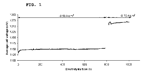
Fig. 1 shows the average cell voltage during operation of a
SOEC stack prepared according to Example 1.
Example 1:
A 300 j.zm thick anode supported cell with internal feeding and
exhaust holes has demasked contact layers in the manifold ar-
eas in order to minimise the leakage through these porous
CA 02774104 2012-03-13
WO 2011/042148 PCT/EP2010/006058
18
structures. A metal gasket frame covered with equally shaped,
punched E-glass fibre paper having a composition according to
the invention (e.g. ASTM D578-05: 52 to 62 wt% Si02, 12 to 16
wt% A1203, 16 to 25 wt% CaO, 0 to 5 wt% MgO, 0 to 2 wt%
Na20+K20, 0 to 10 wt% B203, 0 to 1.5 wt% Ti02, Fe203 0.05 to
0.8 wt% and 0-1 wt% fluoride) on both sides is placed on both
sides of the cell in such a way that air from the manifold
holes is allowed to pass over one electrode (air side), and
such that steam gas is allowed to pass over the other elec-
trode (steam side) of the cell. Above and below the cell and
gasket assemblage, an interconnect plate with manifold holes
is placed. The E-glass paper contains fibres in an amount of
100 g/m2 towards the cell and 50 g/m2 towards the intercon-
nect plate corresponding to a 40 and 20 um, respectively,
thick dense layer after treatment according to the invention
at temperatures of about 880 C and a load pressure of about 6
kg/cm2. Building a stack with 5 cells, a cross-over leak be-
tween the anode and the cathode sides has been measured at RT
to as low as 0.05 and 0.09% in two stacks after a full ther-
mal cycle. With gas chromatography using steps of 2 x N2 con-
centration in oxygen on the air side and measuring the N2
mole concentration on the steam side during operation with
the same gas pressure on the steam and oxygen/air side, we
obtained a doubling of the N2 mole% in the anode of each step
showing that the there is a leakage and that it is diffusion
driven, presumably due to the diffusion through the porous
structures of the cell (mainly the anode support). An in-
creasing of the gas pressure on the oxygen side had no effect
on the cross-over leak on the steam side.
XRD-spectres of the E-glass show the presence of wollaston-
ite, CaSi03 (diopside, (Ca,Mg),Si03 also fit the spectrum and
CA 02774104 2012-03-13
WO 2011/042148 PCT/EP2010/006058
19
its presence depends on the MgO-content of the glass) to-
gether with anorthite (CaAl2Si2O8, which may contain up to 10
mole% NaAlSi3O8) and cristobalite, (Si02).
The flat profile of Fig. 1 shows that the SOEC does not de-
grade significantly during operation. In the electrolysis
mode at 850 C, -0.5A/cm2 45% H20-45CO2-10%H2 the solid oxide
cell stack has operated with a degradation as low as 1%/1000
hours between 30 to 800 hours. At 0.75A/cm the overall volt-
age increase seems to level out before the stack test was
stopped due to a system failure. The degradation rate is low
compared to literature where degradation rates of 2%/1000 or
more in high temperature operation of SOECs are normal. For
instance, degradation rates of 2%/1000 hours at 850 C,
p(H20)/p(H2) = 0.5/0.5 and -0.5A/cm2 and 6%/1000 hours at
950 C p(H20)/p(H2) = 0.1/0.9 and -1.OA/cm2 have been reported
in literature. Normally the degradation has been attributed
to the delamination of the 02 electrode, Cr-contamination, as
well as contamination of the H2-electrode's triple phase
boundary by silica. The silica could also originate from the
interconnect plate. In the present case the low degradation
of 1%/1000 hours, compared to e.g. 2%/1000 hours or more of
prior art SOECs indicates that the E-glass seal does not sig-
nificantly contaminate the electrodes of the cell over 800
hours. Without being bound by any theory the reason for this
appears to be that the E-glass seal was crystallized to a
stable assemblage of MgCaSi2O6, CaSiO3, CaAl2Si2O8 and SiO2
(cristobalite) with a reduced area of exposed (Si04)4- units
compared to the albite glass. Also a smaller exposed surface
due to the design of the stack with very thin layers of seal-
ing glass. Some preliminary results from another stack oper-
ating in electrolysis mode at 0.65 A/cm2 show no degradation
CA 02774104 2012-03-13
WO 2011/042148 PCT/EP2010/006058
so it is unknown to what extent the degradation of 1%/1000
hours is driven by Si or Cr-contamination.
Therefore the invention enables to prepare by simple means
5 (use of E-glass fibre paper as glass sealant precursor) a fi-
nal cell stack in which the components of the stack including
the sealant work well together without creating leakages dur-
ing ordinary operation and thermal cycling. No deteriorating
reactions occur between the oxide scale of the interconnect
10 and the E-glass.