Note: Descriptions are shown in the official language in which they were submitted.
CA 02774397 2012-03-16
WO 2011/038477 PCT/CA2009/001384
1
INLET GRATE CLEANING SYSTEM FOR A WATER JET PROPULSION SYSTEM
FIELD OF THE INVENTION
[0001] The present invention relates to an inlet grate cleaning system for a
water jet
propulsion system and to a watercraft having such a system.
BACKGROUND OF THE INVENTION
[0002] Water jet powered watercraft have become very popular in recent years
for
recreational use and for use as transportation in coastal communities. Water
jet propelled
watercraft offer high performance, improved acceleration and handling, and
shallow-water
operation. Accordingly, personal watercrafts (PWCs), which typically employ
water jet
propulsion units, have become popular, especially in resort areas. As the use
of PWCs has
increased, a desire for improved performance, including greater operational
efficiency, also has
increased.
[0003] Typically, water jet powered watercraft, such as PWCs, have a water jet
propulsion system mounted within the hull that ingests water from a body of
water and expels the
water at a high velocity from the stern to propel the watercraft. For
directional control, a nozzle is
generally provided at the outlet of the jet pump and turning is achieved by
redirecting the flow of
water from the nozzle.
[0004] In the typical arrangement for a water jet propulsion unit, an engine
output shaft is
rotationally coupled to a drive shaft. The drive shaft extends into a water
passage, which is
defined in part by the hull of the watercraft partially below the water line.
The water passage
extends from a point forward of the rear of the watercraft to the rear of the
watercraft. An
impeller disposed within a pump housing portion of the water passage is
attached to the drive
shaft.
[0005] Figure 8 shows a prior art water jet propulsion system 600 disposed
within a hull
612, of which only a portion is shown in broken lines. As shown in Figure 8,
an inlet grate 642 is
disposed at an inlet 686 to an intake ramp 688. A pump support 650 or ride
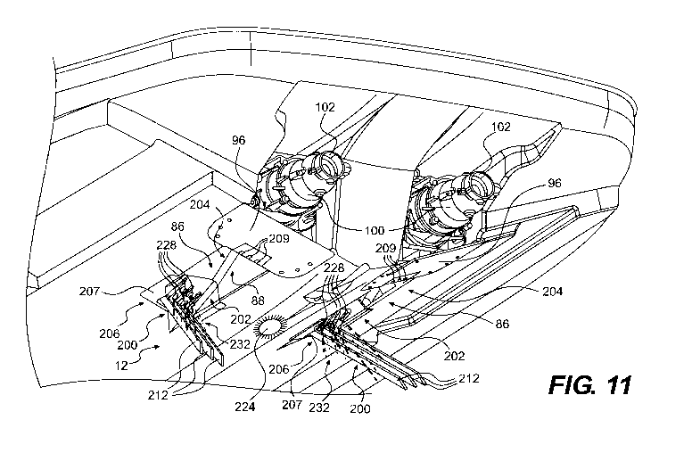
shoe forms the
bottom portion 692 of the water intake ramp 688. The pump support 650 is
coupled to the hull
MONTREAL:23694402
1117515
CA 02774397 2012-03-16
WO 2011/038477 PCT/CA2009/001384
2
612 within a tunnel 694 through fasteners and/or adhesives (not shown). The
pump support 650
includes a main body portion having a vertical attachment surface 652, a
forward attachment
location 654 that is secured to a ride plate 696, and a ramp portion 656. The
ramp portion 656
forms the bottom portion 692 of the water intake ramp 688.
[0006] From the water intake ramp 688, water enters into a jet pump 660. The
jet pump
660 includes an impeller 670 and a stator 680. The impeller includes blades
672 that extend from
a center portion 674 that is coupled to an engine by one or more shafts 698,
such as a drive shaft
and/or an impeller shaft. The rotation of the impeller 670 pressurizes the
water, which then moves
over the stator 680 that comprises a plurality of fixed stator blades 682. The
role of the stator
blades 682 is to decrease the rotational motion of the water so that almost
all the energy given to
the water is used for thrust, as opposed to swirling the water. As shown, the
impeller 670 and the
stator 680 are both disposed within a jet propulsion unit housing 690 or pump
housing. However,
it is also known to position the stator 680 at a position outside of the
housing 690 at a position
downstream of the housing 690. The housing 690 includes a peripheral wall 691
which defines a
passage through which water passes. A forward end 692 of the housing
peripheral wall 691 is
attached to the vertical attachment surface 654 or the pump support 650. The
forward end 692 of
the housing peripheral wall 691 defines the inlet into the housing 690.
[0007] Once the water leaves the jet pump 660, it goes through a venturi 610
disposed at
the rearward end of the housing 690. Since the venturi's exit diameter is
smaller than its entrance
diameter, the water is accelerated further, thereby providing more thrust.
[0008] A steering nozzle 602 is pivotally attached to the venturi 610 so as to
pivot about a
vertical axis 604. The steering nozzle 602 is operatively connected to a
steering mechanism such
as a steering handlebar (see, e.g., the steering handlebar 74 shown in Figure
1). Rotation of the
steering handlebar causes the steering nozzle 602 to pivot around the vertical
axis 604, thereby
directing the water discharge to result in a change in the steering direction
of the watercraft.
[0009] A water passage 695, through which water flows, is illustrated in
Figure 8. With
reference to Figure 8, the water flows from left to right through the passage
695. Moving from
left to right in this illustration, which corresponds to upstream and
downstream positions, the
MONTREAL:23694402
1117515
CA 02774397 2012-03-16
WO 2011/038477 PCT/CA2009/001384
3
water passage 695 is defined by the inlet 686, the water intake ramp 688, the
pump support
passage, the jet pump 660, the venturi 610 and the steering nozzle 602.
[0010] The inlet grate 642 usually comprises a plurality of elongated members
643
extending longitudinally across the inlet 686. Elongated members 643 prevent
large rocks, weeds,
and other debris from entering the water intake ramp 688 and passing through
the water passage
695, which could result in breaking or premature use of the various components
of the water jet
propulsion unit 600. However, depending on the PWC operating conditions, weeds
and debris
may get stuck in the inlet grate 642 and limit the amount of water entering
the water passage 695
through the inlet 686. This may results in decreased acceleration performance,
traveling speed
and/or manoeuvrability. To solve this problem, the operator of the PWC or
someone assisting has
to manually pull out the objects blocking the proper flow of water through the
inlet 686.
[0011] In view of the foregoing, a need has developed for a watercraft with a
water jet
propulsion system that provides for a cleaning system for cleaning objects
stuck in the inlet grate.
In order to address this need, water jet propulsion systems with inlet grates
pivotally mounted to
the hull of the PWC have been developed. These systems allow for the repeated
lowering of the
inlet grate until objects stuck to or between the elongated members are
loosened and eventually
removed from the inlet grate. However, such a system has not proved to provide
satisfactory
performances since some objects may nonetheless remain stuck or the number of
actuations of
the grate necessary to remove some objects is too high.
[0012] Therefore, there is still a need for an inlet grate cleaning system.
SUMMARY OF THE INVENTION
[0013] It is an object of the present invention to ameliorate at least some of
the
inconveniences present in the prior art.
[0014] In one aspect, the invention provides an inlet grate cleaning system
for a water jet
propulsion system to be used in a watercraft. The water jet propulsion system
has a water
passage, the water passage has an inlet and the inlet has a forward area and a
rearward area with
respect to the watercraft. The inlet grate cleaning system comprises a pump
and at least one water
intake fluidly connected to the pump. At least one water outlet is also
fluidly connected to the
MONTREAL:23694402
1117515
CA 02774397 2012-03-16
WO 2011/038477 PCT/CA2009/001384
4
pump. The pump is adapted for pumping water from the at least one water intake
to the at least
one water outlet to create at least one jet of water. The at least one water
outlet is positioned so as
to direct the at least one jet of water toward an inlet grate.
[0015] In an additional aspect, the at least one water outlet includes a
nozzle.
[0016] In a further aspect, the inlet grate cleaning system further comprises
an inlet grate.
The inlet grate comprises a first end portion adapted to be connected to one
of the forward area
and the rearward area of the inlet. At least one elongated member extends from
the first end
portion toward the other of the forward area or the rearward area of the
inlet. The at least one
elongated member is pivotally mounted to the first end portion of the inlet
grate.
[0017] In an additional aspect, the at least one water outlet is positioned at
the first end
portion of the inlet grate.
[0018] In a further aspect, the at least one water outlet includes a nozzle.
[0019] In an additional aspect, the inlet grate cleaning system further
comprises an
actuator operatively connected to the at least one elongated member to pivot
the at least one
elongated member of the inlet grate between a first position and at least a
second position.
[0020] In a further aspect, the inlet grate cleaning system further comprises
a device
operatively connected to the actuator for controlling the operation of the
actuator.
[0021] In another aspect, the inventions provides a watercraft comprising a
hull, a deck
disposed on the hull and a water jet propulsion system connected to the hull.
The water jet
propulsion system has a water passage, the water passage has an inlet and the
inlet has a forward
area and a rearward area with respect to the watercraft. An engine is
supported by the hull and
adapted to drive the water jet propulsion system. An inlet grate is disposed
in the inlet. A pump is
connected to one of the hull or the deck. At least one water intake is fluidly
connected to the
pump. At least one water outlet is fluidly connected to the pump. The pump is
adapted for
pumping water from the at least one water intake to the at least one water
outlet to create at least
one jet of water and the at least one water outlet is positioned so as to
direct the at least one jet of
water toward the inlet grate.
MONTREAL:23694402
1117515
CA 02774397 2012-03-16
WO 2011/038477 PCT/CA2009/001384
[0022] In an additional aspect, at least one portion of the inlet grate is
pivotally mounted
to one of the forward area of the inlet or the rearward area of the inlet.
[0023] In a further aspect, the watercraft further comprises an actuator
operatively
connected to the at least one portion of the inlet grate. The actuator is
adapted to cause the at least
5 one portion of the inlet grate to pivot between a first position and at
least a second position away
from the hull.
[0024] In an additional aspect, the watercraft further comprises a device
operatively
connected to the actuator for controlling the operation of the actuator. The
device is disposed on
the deck so as to be within reach of an operator of the watercraft.
[0025] In a further aspect, the inlet grate has a first end portion adapted to
be connected to
one of the forward area or the rearward area of the inlet and at least one
elongated member
extending from the first end portion toward the other of the forward area or
the rearward area of
the inlet. The at least one elongated member is pivotally mounted to the first
end portion of the
inlet grate.
[0026] In an additional aspect, the watercraft further comprises an actuator
operatively
connected to the at least one elongated member to pivot the at least one
elongated member of the
inlet grate between a first position and at least a second position away from
the hull.
[0027] In a further aspect, the watercraft further comprises a device
operatively connected
to the actuator for controlling the operation of the actuator. The device is
disposed on the deck so
as to be within reach of an operator of the watercraft.
[0028] In an additional aspect, the watercraft further comprises a straddle
seat disposed on
the deck and a handlebar operatively connected to the jet propulsion system
for steering the
watercraft.
[0029] In a further aspect, the water jet propulsion system is a first water
jet propulsion
system having a first water passage, the first water passage having a first
inlet, the inlet grate is a
first inlet, the at least one water outlet is at least one first water outlet.
The watercraft further
comprises a second water jet propulsion system having a second water passage,
the second water
MONTREAL23694402
1117515
CA 02774397 2012-03-16
WO 2011/038477 PCT/CA2009/001384
6
passage having a second inlet, a second inlet grate disposed in the second
inlet and at least one
second water outlet fluidly connected to the pump. The pump is adapted for
pumping water from
the at least one water intake to the at least one second water outlet to
create at least one second jet
of water. The at least one second water outlet is positioned so as to direct
the at least one second
jet of water toward the second inlet grate.
[0030] In an additional aspect, the first inlet and the second inlet are on
opposite sides of a
longitudinal axis of the watercraft.
[0031] In another aspect, the inventions provides a method for cleaning an
inlet grate for a
water jet propulsion system to be used in a watercraft. The water jet
propulsion system has a
water passage, the water passage has an inlet, the inlet has a forward area
and a rearward area
with respect to the watercraft, and an inlet grate is disposed in the inlet.
The method for cleaning
an inlet grate comprises the step of pumping water through a water intake from
a body of water in
which the watercraft is operated to at least one water outlet to create at
least one jet of water
directed toward the inlet grate.
[0032] In an additional aspect, the inlet grate has an end portion connected
to the inlet and
at least one elongated member extends from the end portion. The method for
cleaning an inlet
grate further comprises the step of pivoting the at least one elongated member
of the inlet grate
between a first position and at least a second position away from the hull of
the watercraft, the at
least one jet of water being directed toward the at least one elongated member
when the at least
one elongated member is in the at least second position.
[0033] For purposes of this application, the terms related to spatial
orientation such as
forwardly, rearwardly, left and right, are as they would normally be
understood by a driver of a
vehicle sitting thereon in a normal driving position.
[0034] Embodiments of the present invention each have at least one of the
above-
mentioned objects and/or aspects, but do not necessarily have all of them. It
should be
understood that some aspects of the present invention that have resulted from
attempting to attain
the above-mentioned objects may not satisfy these objects and/or may satisfy
other objects not
specifically recited herein.
MONTREAL23694402
1117515
CA 02774397 2012-03-16
WO 2011/038477 PCT/CA2009/001384
7
[0035] Additional and/or alternative features, aspects, and advantages of
embodiments of
the present invention will become apparent from the following description, the
accompanying
drawings, and the appended claims.
BRIEF DESCRIPTION OF THE DRAWINGS
[0036] For a better understanding of the present invention, as well as other
aspects and
further features thereof, reference is made to the following description which
is to be used in
conjunction with the accompanying drawings, where:
[0037] Figure 1 illustrates a left side elevation view of a personal
watercraft in accordance
with an embodiment of the invention;
[0038] Figure 2 is a top plan view of the watercraft of Figure 1;
[0039] Figure 3 is a front elevation view of the watercraft of Figure 1;
[0040] Figure 4 is a rear elevation view of the watercraft of Figure 1;
[0041] Figure 5 is a bottom plan view of the hull of the watercraft of Figure
1;
[0042] Figure 6 is a perspective view, taken from a front, left side, of a
sport boat in
accordance with an embodiment the invention;
[0043] Figure 7 is a perspective view, taken from a rear, left side, of the
sport boat of
Figure 6;
[0044] Figure 8 is a partial, cross-sectional side view of the stern of a
watercraft showing
a prior art water jet propulsion system;
[0045] Figure 9 is a partial, cross-sectional side view of the stern of the
sport boat of
Figure 6 showing an embodiment of a water jet propulsion system in accordance
with an
embodiment of the invention;
MONTREAL23694402
1117515
CA 02774397 2012-03-16
WO 2011/038477 PCT/CA2009/001384
8
[0046] Figure 10 is a bottom perspective view, taken from rear, left side, of
a portion of
the hull of the sport boat of Figure 6 with the elongated members of the inlet
grate in a first
closed position;
[0047] Figure 11 is another bottom perspective view, taken from rear, left
side, of the
portion of the hull of Figure 10 with the elongated members of the inlet grate
in a second opened
position;
[0048] Figure 12 is a schematic representation of an inlet grate cleaning
system in
accordance with an embodiment of the invention;
[0049] Figure 13 is a top view of a portion of an interior of the hull of the
sport boat of
Figure 6 in accordance with an embodiment of the invention.
DETAILED DESCRIPTION OF THE PREFERRED EMBODIMENTS
[0050] The general construction of a personal watercraft 10 in accordance with
this
invention will be described with respect to Figures 1-5. The following
description relates to one
way of manufacturing a personal watercraft. Obviously, those of ordinary skill
in the watercraft
art will recognize that there are other known ways of manufacturing and
designing watercraft and
that this invention would encompass these other known ways and designs.
[00511 The watercraft 10 of Figure 1 is made of a hull 12 and a deck 14. The
hull 12
buoyantly supports the watercraft 10 in the water. The deck 14 is designed to
accommodate one
or multiple riders. The hull 12 and deck 14 are joined together at a seam 16
that joins the parts in
a sealing relationship. Preferably, the seam 16 comprises a bond line formed
by an adhesive. Of
course, other known joining methods could be used to sealingly engage the
parts together,
including but not limited to thermal fusion, molding or fasteners such as
rivets or screws. A
bumper 18 generally covers the seam 16, which helps to prevent damage to the
outer surface of
the watercraft 10 when the watercraft 10 is docked, for example. The bumper 18
can extend
around the bow, as shown, or around any portion or all of the seam 16.
[0052] The space between the hull 12 and the deck 14 forms a volume commonly
referred
to as the engine compartment 20 (shown in phantom). The engine compartment 20
MONTREAL:23694402
1117515
CA 02774397 2012-03-16
WO 2011/038477 PCT/CA2009/001384
9
accommodates an engine 22, as well as a muffler, tuning pipe, gas tank,
electrical system
(battery, electronic control unit, etc.), air box, storage bins 24, 26, and
other elements required or
desirable in the watercraft 10.
[0053] As seen in Figures 1 and 2, the deck 14 has a centrally positioned
straddle-type
seat 28 positioned on top of a pedestal 30 to accommodate multiple riders in a
straddling position.
As seen in Figure 2, the seat 28 includes a first, front seat portion 32 and a
rear, raised seat
portion 34. The seat 28 is preferably made as a cushioned or padded unit, or
as interfitting units.
The first and second seat portions 32, 34 are removably attached to the
pedestal 30 by a hook and
tongue assembly (not shown) at the front of each seat and by a latch assembly
(not shown) at the
rear of each seat, or by any other known attachment mechanism. The seat
portions 32, 34 can be
individually tilted or removed completely. Seat portion 32 covers an engine
access opening
defined by a top portion of the pedestal 30 to provide access to the engine 22
(Figure 1). Seat
portion 34 covers a removable storage box 26 (Figure 1). A "glove compartment"
or small
storage box 36 is provided in front of the seat 28.
[0054] As seen in Figure 4, a grab handle 38 is provided between the pedestal
30 and the
rear of the seat 28 to provide a handle onto which a passenger may hold. This
arrangement is
particularly convenient for a passenger seated facing backwards for spotting a
water skier, for
example. Beneath the handle 38, a tow hook 40 is mounted on the pedestal 30.
The tow hook 40
can be used for towing a skier or floatation device, such as an inflatable
water toy.
[0055] As best seen in Figures 2 and 4, the watercraft 10 has a pair of
generally upwardly
extending walls located on either side of the watercraft 10 known as gunwales
or gunnels 42.
The gunnels 42 help to prevent the entry of water in the footrests 46 of the
watercraft 10, provide
lateral support for the riders' feet, and also provide buoyancy when turning
the watercraft 10,
since personal watercraft roll slightly when turning. Towards the rear of the
watercraft 10, the
gunnels 42 extend inwardly to act as heel rests 44. A passenger riding the
watercraft 10 facing
towards the rear, to spot a water-skier for example, may place his or her
heels on the heel rests
44, thereby providing a more stable riding position. Heel rests 44 could also
be formed
separately from the gunnels 42.
MONTREAL23694402
1117515
CA 02774397 2012-03-16
WO 2011/038477 PCT/CA2009/001384
[0056] Located on both sides of the watercraft 10, between the pedestal 30 and
the
gunnels 42 are the footrests 46. The footrests 46 are designed to accommodate
the riders' feet in
various riding positions. To this effect, the footrests 46 each have a forward
portion 48 angled
such that the front portion of the forward portion 48 (toward the bow of the
watercraft 10) is
5 higher than the rear portion of the forward portion 48. The remaining
portions of the footrests 46
are generally horizontal. Of course, any contour conducive to a comfortable
rest for the riders
could be used. The footrests 46 are covered by carpeting 50 made of a rubber-
type material, for
example, to provide additional comfort and traction for the feet of the
riders.
[0057] A reboarding platform 52 is provided at the rear of the watercraft 10
on the deck
10 14 to allow the rider or a passenger to easily reboard the watercraft 10
from the water. Carpeting
or some other suitable covering may cover the reboarding platform 52. A
retractable ladder (not
shown) may be affixed to the transom 54 to facilitate boarding the watercraft
10 from the water
onto the reboarding platform 52.
[0058] Referring to the bow 56 of the watercraft 10, as seen in Figures 2 and
3, the
watercraft 10 is provided with a hood 58 located forwardly of the seat 28 and
a helm assembly
60. A hinge (not shown) is attached between a forward portion of the hood 58
and the deck 14 to
allow hood 58 to move to an open position to provide access to the front
storage bin 24 (Fig. 1).
A latch (not shown) located at a rearward portion of hood 58 locks hood 58
into a closed position.
When in the closed position, hood 58 prevents water from entering front
storage bin 24.
Rearview mirrors 62 are positioned on either side of hood 58 to allow the
rider to see behind the
watercraft 10. A hook 64 is located at the bow 56 of the watercraft 10. The
hook 64 is used to
attach the watercraft 10 to a dock when the watercraft 10 is not in use or to
attach to a winch
when loading the watercraft 10 on a trailer, for instance.
[0059] As best seen in Figures 3, 4, and 5, the hull 12 is provided with a
combination of
strakes 66 and chines 68. A strake 66 is a protruding portion of the hull 12.
A chine 68 is the
vertex formed where two surfaces of the hull 12 meet. The combination of
strakes 66 and chines
68 provide the watercraft 10 with its riding and handling characteristics.
[0060] Sponsons 70 are located on both sides of the hull 12 near the transom
54. The
sponsons 70 have an arcuate undersurface that gives the watercraft 10 both
lift while in motion
MONTREAL:23694402
1117515
CA 02774397 2012-03-16
WO 2011/038477 PCT/CA2009/001384
11
and improved turning characteristics. The sponsons 70 are fixed to the surface
of the hull 12 and
can be attached to the hull 12 by fasteners or molded therewith. It is
contemplated that the
position of the sponsons 70 with respect to the hull 12 may be adjustable to
change the handling
characteristics of the watercraft 10 and accommodate different riding
conditions. Trim tabs,
which are commonly known, may also be provided at the transom and may be
controlled from the
helm 60.
[0061] As best seen in Figures 3 and 4, the helm assembly 60 is positioned
forwardly of
the seat 28. The helm assembly 60 has a central helm portion 72, that is
padded, and a pair of
steering handles 74, also referred to as a handlebar. One of the steering
handles 74 is provided
with a throttle operator 76, which allows the rider to control the engine 22,
and therefore the
speed of the watercraft 10. The throttle operator 76 can be in the form of a
thumb-actuated
throttle lever (as shown), a finger-actuated throttle lever, or a twist grip.
The throttle operator 76
is movable between an idle position and multiple actuated positions. In a
preferred embodiment,
the throttle operator 76 is biased towards the idle position, such that,
should the driver of the
watercraft 10 let go of the throttle operator 76, it will move to the idle
position. The other of the
steering handles 74 is provided with a reverse gate operator 77 used by the
driver to actuate a
reverse gate 110 of the watercraft 10 as described in greater detail below.
The reverse gate
operator 77 is a finger-actuated lever. However, it is contemplated that the
reverse gate operator
77 could be a thumb-actuated lever or a twist grip.
[0062] As seen in Figure 2, a display area or cluster 78 is located forwardly
of the helm
assembly 60. The display cluster 78 can be of any conventional display type,
including a liquid
crystal display (LCD), dials or LED (light emitting diodes). The central helm
portion 72 has
various buttons 80, which could alternatively be in the form of levers or
switches, that allow the
driver to modify the display data or mode (speed, engine rpm, time...) on the
display cluster 78 or
to change a condition of the watercraft 10, such as trim (the pitch of the
watercraft 10).
[0063] The helm assembly 60 is provided with a key receiving post 82 located
near a
center of the central helm portion 72. The key receiving post 82 is adapted to
receive a key (not
shown) that starts the watercraft 10. As is known, the key is typically
attached to a safety lanyard
(not shown). It should be noted that the key receiving post 82 may be placed
in any suitable
location on the watercraft 10.
MONTREAL:23694402
1117515
CA 02774397 2012-03-16
WO 2011/038477 PCT/CA2009/001384
12
[0064] Returning to Figures 1 and 5, the watercraft 10 is propelled by a water
jet
propulsion system 84. As is known, the water jet propulsion system 84
pressurizes water to
create thrust. The water is first scooped from under the hull 12 through an
inlet 86, which has an
inlet grate 200. The inlet grate 200 prevents large rocks, weeds, and other
debris from entering
the water jet propulsion system 84, which may damage the system or negatively
affect
performance. The inlet grate 200 will be described in greater detail below.
Water flows from the
inlet 86 through a water intake ramp 88. The top portion 90 of the water
intake ramp 88 is
formed by the hull 12, and a ride shoe (not shown in detail) forms its bottom
portion 92.
Alternatively, the intake ramp 88 may be a single piece or an insert to which
the jet pump (not
shown) of the water jet propulsion system 84 attaches. In such cases, the
intake ramp 88 and the
jet pump are attached as a unit in a recess in the bottom of hull 12.
[0065] From the intake ramp 88, water enters the jet pump. The jet pump is
located in a
formation in the hull 12, referred to as the tunnel 94. The tunnel 94 is
defined at the front, sides,
and top by the hull 12 and is open at the transom 54. The bottom of the tunnel
94 is closed by the
ride plate 96. The ride plate 96 creates a surface on which the watercraft 10
rides or planes at
high speeds.
[0066] The jet pump includes an impeller (not shown) and a stator (not shown).
The
impeller is coupled to the engine 22 by one or more shafts 98, such as a
driveshaft and an
impeller shaft. The rotation of the impeller pressurizes the water, which then
moves over the
stator that is made of a plurality of fixed stator blades (not shown). The
role of the stator blades
is to decrease the rotational motion of the water so that almost all the
energy given to the water is
used for thrust, as opposed to swirling the water. Once the water leaves the
jet pump, it goes
through a venturi 100. Since the venturi's exit diameter is smaller than its
entrance diameter, the
water is accelerated further, thereby providing more thrust. A steering nozzle
102 is pivotally
attached to the venturi 100 so as to pivot about a vertical axis 104. The
steering nozzle 102 could
also be supported at the exit of the tunnel 94 in other ways without a direct
connection to the
venturi 100. Moreover, the steering nozzle 102 can be replaced by a rudder or
other diverting
mechanism disposed at the exit of the tunnel 94 to selectively direct the
thrust generated by the
water jet propulsion system 84 to effect turning.
MONTREAL23694402
1117515
CA 02774397 2012-03-16
WO 2011/038477 PCT/CA2009/001384
13
[0067] The steering nozzle 102 is operatively connected to the helm assembly
60
preferably via a push-pull cable (not shown) such that when the helm assembly
60 is turned, the
steering nozzle 102 pivots. This movement redirects the pressurized water
coming from the
venturi 100, so as to redirect the thrust and steer the watercraft 10 in the
desired direction.
Optionally, the steering nozzle 102 may be gimbaled to allow it to move around
a second
horizontal pivot axis (as shown in Figures 8 and 9). The up and down movement
of the steering
nozzle 102 provided by this additional pivot axis is known as trim and
controls the pitch of the
watercraft 10.
[0068] When the watercraft 10 is moving, its speed is measured by a speed
sensor 106
attached to the transom 54 of the watercraft 10. The speed sensor 106 has a
paddle wheel 108
that is turned by the water flowing past the hull 12. In operation, as the
watercraft 10 goes faster,
the paddle wheel 108 also turns faster. An electronic control unit (ECU) (not
shown) connected
to the speed sensor 106 converts the rotational speed of the paddle wheel 108
to the speed of the
watercraft 10 in kilometers or miles per hour, depending on the rider's
preference. The speed
sensor 106 may also be placed in the ride plate 96 or at any other suitable
position. Other types
of speed sensors, such as pitot tubes, and processing units could be used, as
would be readily
recognized by one of ordinary skill in the art. Alternatively, a global
positioning system (GPS)
unit could be used to determine the speed of the watercraft 10 by calculating
the change in
position of the watercraft 10 over a period of time based on information
obtained from the GPS
unit.
[0069] The watercraft 10 is provided with the ability to move in a reverse
position. A
reverse gate 110 which is movable between a first stowed position where it
does not interfere
with the jet of water (indicated by arrows 85) being expelled by the water jet
propulsion system
84 and a plurality of positions where it redirects the jet of water 85 being
expelled by the water jet
propulsion system 84, thus causing the watercraft 10 to move in a reverse
direction. A reverse
gate actuator (not shown) is operatively connected to the reverse gate 110 to
move the reverse
gate 110. The reverse gate actuator could be any one of a mechanical, a
hydraulic, or an electric
actuator, such as an electric motor.
[0070] The general construction of a sport boat 120 in accordance with this
invention will
now be described with respect to Figures 6 and 7. The following description
relates to one way
MONTREAL23694402
1117515
CA 02774397 2012-03-16
WO 2011/038477 PCT/CA2009/001384
14
of manufacturing a sport boat. Obviously, those of ordinary skill in the sport
boat art will
recognize that there are other known ways of manufacturing and designing sport
boats and that
this invention would encompass these other known ways and designs.
[0071] For simplicity, the components of the sport boat 120 which are similar
in nature to
the components of the personal watercraft 10 described above will be given the
same reference
numeral. It should be understood that their specific construction may vary
however.
[0072] The sport boat 120 has a hull 12 and a deck 14 supported by the hull
12. The deck
14 has a forward passenger area 122 and a rearward passenger area 124. A right
console 126 and
a left console 128 are disposed on either side of the deck 14 between the two
passenger areas 122,
124. A passageway 130 disposed between the two consoles 126, 128 allows for
communication
between the two passenger areas 122, 124. A door 131 is used to selectively
open and close the
passageway 130. In an embodiment of the invention, at least one engine is
located between the
hull 12 and the deck 14 at the back of the boat 120 and powers the water jet
propulsion system
(not shown) of the boat 120. In the embodiment of the invention shown in
Figures 6 and 7, two
engines power two jet propulsion systems 184a and 184b. Each water jet
propulsion systems 184a
and 184b has an inlet 86. The inlets 86 are disposed on opposite sides of a
longitudinal axis of the
sport boat 120. The water jet propulsion systems 184a and 18b are of similar
construction as the
water jet propulsion system 84 of the personal watercraft 10 described above.
In an embodiment
of the invention, at least one reverse gate 110 is operatively mounted to the
hull 12. In the
embodiment of the invention shown in Figures 6 and 7, one reverse gate 110 is
provided for each
of the two water jet propulsion systems 184a and 184b. The reverse gates 110
are of similar
construction as the reverse gate 110 of the personal watercraft 10 described
above, and will
therefore not be described again. The engines are accessible through an engine
cover 132 located
behind the rearward passenger area 124. The engine cover 132 can also be used
as a sundeck for
a passenger of the boat 120 to sunbathe on while the boat 120 is not in
operation. A reboarding
platform 52 is located at the back of the deck 14 for passengers to easily
reboard the boat 120
from the water.
[0073] The forward passenger area 122 has a C-shaped seating area 136 for
passengers to
sit on. The rearward passenger area 124 also has a C-shaped seating area 138
at the back thereof.
A driver seat 140 facing the right console 126 and a passenger seat 142 facing
the left console
MONTREAL:23694402
1117515
CA 02774397 2012-03-16
WO 2011/038477 PCT/CA2009/001384
124 are also disposed in the rearward passenger area 124. It is contemplated
that the driver and
passenger seats 140, 142 can swivel so that the passengers occupying these
seats can socialize
with passengers occupying the C-shaped seating area 138. A windshield 139 is
provided at least
partially on the left and right consoles 124, 126 and forwardly of the
rearward passenger area 124
5 to shield the passengers sitting in that area from the wind when the boat
120 is in movement. The
right and left consoles 126, 128 extend inwardly from their respective side of
the boat 120. At
least a portion of each of the right and the left consoles 126, 128 is
integrally formed with the
deck 14. The right console 126 has a recess 144 formed on the lower portion of
the back thereof
to accommodate the feet of the driver sitting in the driver seat 140 and an
angled portion of the
10 right console 126 acts as a footrest 146. A reverse gate operator, in the
form of a foot pedal 147,
is provided on the footrest 146. It is contemplated that the foot pedal 147
could be replaced by a
handle positioned near or on the steering wheel 149. The function of the foot
pedal 147 is similar
to that of the reverse gate operator 77 of the personal watercraft 10. The
left console 128 has a
recess (not shown) similar to recess 144 to accommodate the feet of the
passenger sitting in the
15 passenger seat 142. The right console 126 accommodates all of the elements
necessary to the
driver to operate the boat. These include, but are not limited to, a helm
assembly in the form of
the steering wheel 149, a throttle operator 76 in the form of a throttle
lever, and an instrument
panel 152. The instrument panel 152 have various dials indicating the
watercraft speed, engine
speed, fuel and oil level, and engine temperature. The speed of the boat 120
is measured by a
speed sensor (not shown) which can be in the form of the speed sensor 106
described above with
respect to the personal watercraft 10 or a GPS unit or any other type of speed
sensor which could
be used for marine applications. It is contemplated that the elements attached
to the right console
126 could be different than those mentioned above. The left console 128
incorporates a storage
compartment (not shown) which is accessible to the passenger sitting the
passenger seat 142.
[0074] Turning to Figure 9, the water jet propulsion system 184a of a sport
boat such as
the sport boat of Figures 6 and 7 will now be described in more detail. The
water jet propulsion
system 184b of the sport boat of Figures 6 and 7 and the water jet propulsion
system 84 of the
personal watercraft 10 of Figures 1 to 5 are of similar construction as the
water jet propulsion
system 184a.
MONTREAL23694402
1117515
CA 02774397 2012-03-16
WO 2011/038477 PCT/CA2009/001384
16
[0075] The water jet propulsion system 184a is disposed within the hull 12,
only a portion
of which is shown in broken lines to reveal the details of the water jet
propulsion system
184a.The water jet propulsion system 184a includes an inlet 86 in the hull 12
that leads to a water
intake ramp 88 in the tunnel 94. A pump support 150 is secured within the
tunnel 94. The water
intake ramp 88 is defined by an interior wall 89 and a ramp portion 156 of the
pump support 150.
The jet pump 160 is secured within the tunnel 94 to the pump support 150. The
venturi 100 and
the steering nozzle 102 that pivot about the vertical axis 104 are disposed at
the rearward end of
the tunnel 94. The inlet 86, intake ramp 88, tunnel 94, venturi 100 and
steering nozzle 102 define
a water passage 87 through which water used in the water jet propulsion system
184a is flowing.
[0076] Turning to Figures 9 to 13, the inlet grate 200 and embodiments of an
inlet grate
cleaning system 201 will now be described in more detail with respect to the
sport boat 120.
However, it should be understood that a similar system is used on the personal
watercraft 10
having a single water jet propulsion system 84.
[0077] As shown in Figures 9 to 11, the inlet 86 has a forward area 202 and a
rearward
area 204.
[0078] As shown in Figures 9 to 12, the inlet grate 200 has a first end
portion 206. The
first end portion 206 of the inlet grate 200 includes a first plate 207. The
first end portion 206 of
the inlet grate 200 is adjacent to the forward area 202 of the inlet 86 and
connected thereto
through the first plate 207. In an embodiment of the invention, the first end
portion 206 of the
inlet grate 200 is connected to the inlet 86 by bolts (not shown) passing
through apertures (not
shown) defined in the first plate 207 of the inlet grate 200. It is
contemplated that a seal (not
shown) may be disposed between the first plate 207 of the inlet grate 200 and
the forward area
202 of the inlet 86. It is also contemplated that in other embodiments of the
invention, the inlet
grate 200 could be disposed the other way around with respect to the inlet 86.
In such
embodiments of the invention, the first end portion 206 of the inlet grate 200
would be adjacent
to the rearward area 204 of the inlet 86 and connected thereto through the
first plate 207.
[0079] Elongated members 212 extend from the first end portion 206 of the
inlet grate
200 toward the rearward area 204 of the inlet 86. In an embodiment of the
invention shown in
MONTREAL23694402
1117515
CA 02774397 2012-03-16
WO 2011/038477 PCT/CA2009/001384
17
Figures 9, the end of the elongated members 212 closer to the rearward area
204 of the inlet 86
are free and abut a recess 209 in the ride plate 96 when in a "closed"
position.
[0080] In an embodiment of the invention, the inlet grate 200 is made of
casted
aluminum. It is contemplated that, in alternative embodiments of the
invention, the various parts
of the inlet grate 200 could be made of the same or various materials suitable
for such use,
including various plastics or composite material as well as various non-
corrosive metallic
materials such as stainless steel.
[0081] In the embodiment of the invention shown in Figures 9 to 12, the
elongated
members 212 are pivotally mounted to the first plate 207 of the inlet grate
200 via the shaft 214.
Elongated members 212 can be moved from a first "closed" position where, as
shown in Figures
9 and 10, elongated members 212 abut the recess 209, to a second "opened"
position where, as
shown in Figure 11, the elongated members 212 define an angle with the hull 12
and extend
below the hull 12. In this embodiment of the invention, the shaft 214 is
disposed in the forward
area 202 of the inlet 86 and the free ends of the elongated members 212 is in
the rearward area
204 of the inlet 86 when in the first "closed" position. It is also
contemplated that if the inlet grate
200 the other way around with respect to the inlet 86 as discussed above, the
shaft 214 would be
disposed in the rearward area 204 of the inlet 84 and the free ends of the
elongated members 212
in the forward area 202 of the inlet 86.
[0082] As shown in Figures 12, an actuator 216, in this embodiment of the
invention an
electric motor (not shown) covered by a housing to protect it from
infiltration of water, is
operatively connected to the shaft 214 via a shaft and bevel gears (not
shown). The housing of the
actuator 216 is also connected to the hull 12 via brackets 215. It is
contemplated that the actuator
216 could be any type of actuator, such as a mechanical, hydraulic or electric
actuator. It is also
contemplated that the elongated members could be pivoted via a shaft and lever
assembly (not
shown) operated an operator of the watercraft.
[0083] In the embodiment of the invention shown in Figures 12 and 13, the
actuator 216
is controlled through a device disposed within reach of an operator of the
watercraft. In the
embodiment of the invention shown in Figure 7, the device comprises a first
button 218
alternatively commending the downward and upward movements of the elongated
members 212.
MONTREAL23694402
1117515
CA 02774397 2012-03-16
WO 2011/038477 PCT/CA2009/001384
18
[0084] As shown in Figure 9 and 12, a pump 220 is connected to the inside wall
of the
hull 12. In other embodiments of the invention, the pump 220 could be disposed
at any suitable
location on the watercraft, including on the deck 14. The pump 220 is
controlled through a device
disposed with reach of an operator of the watercraft. In the embodiment of the
invention shown in
Figure 7, the device comprises a second button 222 controlling the operation
of the pump 220. It
is contemplated that the first button 218 and second button 222 could be a
single button (not
shown) controlling both the actuator 216 and pump 220.
[0085] As sown in Figure 9 to 12, a water intake 224 is disposed in the hull
12 and is
connected to the pump 220 through a hose 226. In an alternative embodiment of
the invention,
the water intake 224' could be disposed in the water passage 87, preferably in
the interior wall 89
of the water intake ramp 88, and connected to the pump 220 through the hose
226'. In another
alternative embodiment of the invention shown in Figure 13, two water intakes
224a and 224b are
disposed in the hull 12 and connected to the pump 220 through two hoses 226a
and 226b. In other
embodiments of the invention, water intakes 224a and 224b are respectively
connected to a first
pump (not shown) and a second pump (not shown) through hoses 226a and 226b
respectively.
[0086] As shown in Figures 9 to 12, four nozzles 228 are connected to the
first plate 207
of the inlet grate 200. The nozzles 228 are positioned so as to point downward
toward each of the
elongated members 212 of the inlet grate 220 when these elongated members 212
are pivoted to a
second "opened" position. As shown in Figures 9 and 12, the four nozzles 228
are connected to
the pump 220 through hoses 230. It is contemplated that in alternative
embodiments of the
invention, only one nozzle 228 may be sufficient. In yet other embodiments of
the invention,
more than four nozzles 228 may be disposed in various areas of the inlet 86.
[0087] To operate the inlet grate cleaning system 201, an operator of the
watercraft
presses the first button 218 to pivot the elongated members 212 of the inlet
grate 200 from a first
"closed" position where the ends of the elongated members 212 abut the recess
209, to a second
"opened" position where the elongated members 212 define an angle with the
hull 212 below the
hull 212. The operator of the watercraft then presses the second button 222 to
activate the pump
220 which pumps water from the body of water on which the watercraft is
operated through the
water intake 224 to the four nozzles 228 to create four jets of water 232
oriented toward various
regions of the inlet grate 220, including the elongated members 212 in order
to loosen and
MONTREAL23694402
1117515
CA 02774397 2012-03-16
WO 2011/038477 PCT/CA2009/001384
19
remove objects, including weeds, pieces of weed, small rocks and dirt, stuck
to the inlet grate
200. Once he is satisfied that the inlet grate 220 has been properly cleaned,
the operator of the
watercraft presses the first button 218 again to pivot the elongated members
212 of the inlet grate
200 from the second "opened" position described above to the first "closed"
position described
above.
[0088] It is contemplated that the inlet grate 200 and elongated members 212
could be
fixed and that cleaning of the inlet grate 200 may be accomplished solely
through the use of the
jets of water 232.
[0089] Modifications and improvements to the above-described embodiments of
the
present invention may become apparent to those skilled in the art. The
foregoing description is
intended to be exemplary rather than limiting. The scope of the present
invention is therefore
intended to be limited solely by the scope of the appended claims.
MONTREAL:23694402
1117515