Note: Descriptions are shown in the official language in which they were submitted.
CA 02774491 2016-04-05
FREEZE DRYING SYSTEM
BACKGROUND OF THE INVENTION
[0002] The invention is directed towards a method and apparatus for
freeze drying. More particularly, the invention is directed to a method and
apparatus for freeze drying by improving the uniformity of freezing and ice
nucleation during the initial freezing phase.
[0003] A typical pharmaceutical freeze drying or lyophilization system
involves the freezing and subsequent freeze drying of hundreds to thousands of
small vials containing the typically aqueous based product to be processed.
The
freezing is typically accomplished by passing a refrigerant through the cold
plates
upon which the vials are placed; however, the temperature at which the
freezing
occurs can vary widely from vial to vial. While there is a maximum temperature
at which freezing will occur (0 C for pure water), the minimum temperature can
be 10 to 20 degrees Celsius or more below 0 C. This difference between the
equilibrium freezing point and the temperature at which ice crystals first
form in
the sample is known as the degree of supercooling. This supercooling varies
from vial to vial and causes variation in the freeze dried product, increased
freezing and primary drying time. Further potentially degraded product quality
can result because of smaller than desired ice crystals which form at large
degrees of supercooling. A high degree of supercooling produces a greater
number of small ice crystals and results in smaller pore sizes in the freeze
dried
product. This in turn increases product resistance and primary drying time
since
smaller pores restrict vapor flow.
- -
CA 02774491 2012-03-16
WO 2011/034980
PCT/US2010/049032
[0004] In scale-up from laboratory to production (i.e., "dirty" to sterile
environment) nucleation can occur at much lower temperatures causing greater
supercooling and extended primary drying times. Additionally, due to inter-
vial
variability in nucleation temperatures, vials with a lower degree of
supercooling
may finish primary drying first and be negatively impacted by overheating.
Variability in freezing is a significant scale-up problem because a freezing
procedure optimized in the laboratory may not transfer exactly to a
manufacturing scale. The extension in primary drying time is usually the more
serious problem, particularly if unrecognized and fixed cycle times are used.
It is
thus important to be able to control the nucleation temperature in order to
control
resistance and drying times.
[0005] A method widely used in commercial freeze dryers to remove
variations in pore size and drying behavior is annealing. During annealing, a
phenomenon called Oswald ripening occurs wherein larger ice crystals form at
the expense of smaller ones leading to a product with larger pore size and
shorter primary drying times. Annealing is not suitable for heat labile and
protein
based formulations (W. Wang: International Journal of Pharmaceutics 203
(2000) 1-60). In such scenarios, the ability to control the nucleation
temperature
to ensure product homogeneity is of paramount importance.
[0006] One approach for improving the uniformity of freezing, as well as
freezing at the desired degree of supercooling which is typically at as high a
temperature as possible, is to introduce nucleating particles. A particularly
advantageous nucleating particle is water ice for aqueous based products in
the
form of an ice fog' introduced into the freezing chamber. Such a process is
described in Rambhatla et al. "Heat and Mass Transfer Scale-up Issues During
Freeze Drying: II. Control and Characterization of the Degree of Subcooling",
- 2 -
CA 02774491 2012-03-16
WO 2011/034980
PCT/US2010/049032
AAPS PharmaSciTech 2004; 5(4). The concept of temperature controlled ice
nucleation was earlier suggested by T. W. Rowe in 1990 (International
Symposium on Biological Product Freeze-Drying and Formulation; Geneva,
Switzerland). Cold nitrogen gas is introduced into a humidified environment
inside the freeze drying chamber to form an ice fog after the vials have
achieved
the temperature at which nucleation is desired. The ice crystals subsequently
make their way into the vials, possibly aided by an increase in chamber
pressure,
and induce nucleation inside the vial. Although this technique has found
success on a laboratory scale, it has proven difficult to scale up to
commercial
freeze dryers. The difficulty is not only forming the ice fog, but also
uniformly
distributing the ice fog rapidly throughout the freezing chamber to ensure all
vials
are properly seeded with nucleating ice particles.
[0007] The invention provides an improvement over the 'ice fog' method for
producing uniformly frozen products during the initial phase of freeze drying
by
rapidly and uniformly distributing the ice fog throughout the freezing
chamber.
SUMMARY OF THE INVENTION
[0008] In one embodiment of the invention there is disclosed, a method for
freeze drying comprising feeding a cryogenic fluid through a venturi device
into a
freeze drying chamber.
[0009] In another embodiment of the invention, there is disclosed a method
of
feeding a cryogenic fluid into a freeze drying chamber comprising feeding the
cryogenic fluid into a venturi device.
- 3 -
CA 02774491 2012-03-16
WO 2011/034980
PCT/US2010/049032
[0010] In a further embodiment of the invention, there is disclosed a
method
of distributing a cryogenic fluid throughout a freeze drying chamber
comprising
feeding the cryogenic fluid through a venturi device.
[0011] In yet another embodiment of the invention, there is disclosed a
method of forming an ice fog in a freeze drying chamber comprising feeding a
cryogenic fluid through a venturi device into the freeze drying chamber.
[0012] In yet a further embodiment, there is disclosed a method for
providing
a uniform dispersion of nucleating ice crystals in a freeze drying chamber
comprising feeding a cryogenic fluid into a venturi device into the freeze
drying
chamber.
[0013] In a different embodiment of the invention, there is disclosed an
apparatus comprising a freeze drying chamber and a venturi device. The venturi
device may be any venturi device such as an ejector.
[0014] The cryogenic fluid may be any type of cryogenic fluid such as
liquid
nitrogen, oxygen, air, argon and mixtures of these. The cryogenic fluid used
to
drive the venturi device may be in a liquid, vapor or two-phase condition. The
pressure of the cryogenic fluid can be any pressure greater than the pressure
of
the freezing chamber with 1 to 10 bar above freezing chamber preferred.
[0015] The nucleating ice crystals may be formed from any suitable
condensable vapor, including water or other gases. The condensable vapor
such as water vapor may be introduced by any mechanism, either before or
during the ice fog formation, and may be introduced directly into or
downstream
of the venturi device.
- 4 -
CA 02774491 2012-03-16
WO 2011/034980
PCT/US2010/049032
[0016] The cryogenic fluid, steam or other fluids introduced into the
freezing
chamber may be suitably processed, such as by filtration and other techniques,
to produce sterile fluids.
[0017] The cold gas generated by the process including the presence of the
ice fog, as well as the rapid and uniform distribution of cold gas/ice fog,
may be
used in other steps of the freeze drying process to facilitate uniformity
and/or the
rate of cooling.
[0018] A variety of venturi devices may be employed in the invention as
well
as multiple venturi devices used together to facilitate uniform distribution.
Additional flow distribution devices such as distribution pipes and turning
vanes
may also be employed.
[0019] A variety of pressure variations through the freezing process and/or
nucleating ice step are possible beyond those earlier stated.
[0020] The products to be freeze dried may be of any type and may be
contained in any configuration within the freezing chamber including vials,
trays
or other types or combinations of containers.
[0021] The ice fog is typically formed when a cryogenic fluid contacts a
humid
gas or suitable condensable vapor. The humidity freezes out and generates a
dispersion of small ice nuclei. The source of the humidity may be any suitable
source but it is typically water.
- 5 -
CA 02774491 2012-03-16
WO 2011/034980
PCT/US2010/049032
BRIEF DESCRIPTION OF THE DRAWINGS
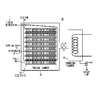
[0022] The figure is a schematic illustration of a freeze drying system
employing the method of the invention.
DETAILED DESCRIPTION OF THE INVENTION
[0023] Turning to the figure, a typical freeze drying system 10 is
depicted.
The apparatus and method of the invention is also depicted wherein the suction
of the venturi device 20 is connected to a distributor 25, and the discharge
delivers a mixed cooling fluid into the freezing chamber 15. Other
arrangements
of the distribution piping are possible, including distributor piping at the
discharge
of the venturi device. The venturi device here is an ejector but other venturi
devices can be employed in the invention. The vials 30 containing the product
to
be freeze dried are placed on the cold plates 35 inside the freezing chamber.
The initial phase of the freezing process is generally conducted at
atmospheric
pressure and the vials are generally cooled to a suitable temperature at or
below
their maximum freezing point temperature. Not shown is a means to provide
humidified atmosphere within the freeze drying chamber, which may be from the
moisture normally contained in atmospheric air, or artificially introduced
through
the injection of steam, a moisture vapor containing gas, or alternative
humidification means. Alternatively the moisture may be partially or totally
introduced directly into or downstream of the venturi device 20.
[0024] When the suitable vial temperature is achieved, liquid nitrogen 1 at
an
elevated pressure is introduced into the venturi device, in this case ejector
20.
The ejector 20 serves two purposes. First, it provides an extremely efficient
means for cooling the humidified air within the chamber and forming the ice
fog.
Second, the suitably sized ejector provides a pumping capacity that can
provide
- 6 -
CA 02774491 2012-03-16
WO 2011/034980
PCT/US2010/049032
a circulation of the ice fog throughout the freezing chamber 15 very rapidly.
It is
a significant advantage that the ejector can accomplish both these functions
without introducing any moving parts or other complicated mechanisms that
would be difficult to steam or otherwise sterilize. One arrangement for the
ejector is shown in the figure which introduces a distributor 25 which creates
a
negative pressure that draws the ice fog throughout the system 10 and the
multiple shelves or cold plates 35. Multiple ejectors can also be employed as
well as providing the ejector 10 at other positions around the freezing
chamber.
[0025] During the formation of the ice fog, the distribution of the
nucleating ice
crystals into each vial can be facilitated by the simultaneous or subsequent
pressurization of the chamber. This pressurization forces gas containing the
ice
crystals into each vial. This pressurization may be accomplished by a variety
of
means, and may be facilitated by performing a depressurization of the freezing
chamber through the use of a vacuum pump 40 before beginning the ice fog
formation. Self-pressurization of the chamber is possible simply by the
introduction of the vaporizing liquid nitrogen 1 where vent valve V1 is
closed.
Valve V2 is opened and the vacuum pump 40 draws the gas through a
condensing chamber 45. Alternatively, additional gas such as air or nitrogen
may be introduced into the chamber to increase the chamber pressure. Both
methods of pressurization can also be employed in tandem. Additionally, rapid
depressurization following the ice fog introduction may be used to improve the
nucleating phenomenon.
[0026] While this invention has been described with respect to particular
embodiments thereof, it is apparent that numerous other forms and
modifications
of the invention will be obvious to those skilled in the art. The appended
claims
in this invention generally should be construed to cover all such obvious
forms
- 7 -
CA 02774491 2016-04-05
and modifications which are within the scope of the present
invention.
- 8 -