Language selection

Search

Patent 2774492 Summary

Third-party information liability

Some of the information on this Web page has been provided by external sources. The Government of Canada is not responsible for the accuracy, reliability or currency of the information supplied by external sources. Users wishing to rely upon this information should consult directly with the source of the information. Content provided by external sources is not subject to official languages, privacy and accessibility requirements.

Claims and Abstract availability

Any discrepancies in the text and image of the Claims and Abstract are due to differing posting times. Text of the Claims and Abstract are posted:

  • At the time the application is open to public inspection;
  • At the time of issue of the patent (grant).
(12) Patent Application: (11) CA 2774492
(54) English Title: MODIFICATION TO A TBM STRUCTURE TO PROVIDE ROOF SUPPORT INSTALLATION
(54) French Title: MODIFICATION APPORTEE A UNE STRUCTURE DE TUNNELIER POUR REALISER UNE INSTALLATION DE SUPPORT DE TOIT
Status: Deemed Abandoned and Beyond the Period of Reinstatement - Pending Response to Notice of Disregarded Communication
Bibliographic Data
(51) International Patent Classification (IPC):
  • E21D 9/11 (2006.01)
  • E21D 11/18 (2006.01)
  • E21D 11/40 (2006.01)
(72) Inventors :
  • MCNALLY, MICHAEL P. (Canada)
(73) Owners :
  • MICHAEL P. MCNALLY
(71) Applicants :
  • MICHAEL P. MCNALLY (Canada)
(74) Agent: EDWARD H. OLDHAMOLDHAM, EDWARD H.
(74) Associate agent:
(45) Issued:
(86) PCT Filing Date: 2009-01-30
(87) Open to Public Inspection: 2010-01-14
Availability of licence: N/A
Dedicated to the Public: N/A
(25) Language of filing: English

Patent Cooperation Treaty (PCT): Yes
(86) PCT Filing Number: PCT/CA2009/000107
(87) International Publication Number: WO 2010003213
(85) National Entry: 2012-04-23

(30) Application Priority Data:
Application No. Country/Territory Date
61/129,594 (United States of America) 2008-07-07

Abstracts

English Abstract

A TBM having a cylindrically shaped member located on said TBM just behind the rotating boring head, said member being of similar diameter as said tunnel and comprising sectionalized components so as to be adjustable in diameter, said member having a plurality of steel angle members welded to the surface of the top-most component so as to extend axially along the length of said cylindrically shaped member, said steel angle members forming axially extending receptacles therein.


French Abstract

L'invention porte sur un tunnelier comportant un élément de forme cylindrique situé sur ledit tunnelier juste derrière la tête de forage rotative, ledit élément ayant un diamètre similaire à celui dudit tunnel, et comprenant des composants en section afin d'avoir un diamètre réglable, ledit élément comportant une pluralité d'éléments de cornières en acier soudés à la surface du composant supérieur de façon à s'étendre axialement le long de la longueur dudit élément de forme cylindrique, lesdits éléments de cornières en acier formant des réceptacles s'étendant axialement à l'intérieur de ceux-ci.

Claims

Note: Claims are shown in the official language in which they were submitted.

What is claimed:
1. A TBM having an axially extending frame, a rotating head, a
non-rotating stabilizing device, a propulsion means, and a
conveyor extending axially along the length of said TBM,
said rotating head being suitably journalled in said
stabilizing head for rotation on said TBM in close proximity
behind said rotating head,
said stabilizing device being mounted on said frame
and having the shape of a hollow cylinder such that the
stabilizing device has an outer diameter which is
substantially equal to the diameter of said rotating head, and
said stabilizing device has a plurality of axially
extending elongated receptacles formed therein.
2. A TBM as claimed in claim 1 wherein said receptacles
extend substantially the entire length of said stabilizing
member.
3. A TBM as claimed in claim 2 wherein said stabilizing device
comprises at least a top and a bottom section of said plurality
of receptacles is located in the top section of said stabilizing
device.
12

4. A TBM as claimed in claim 3 wherein said top and bottom
sections of said stabilizing device are slidably connected
together at sliding joints to allow the diameter of said
stabilizing device to be adjustable within certain
predetermined limits.
5. A TBM as claimed in claim 1 wherein said receptacles are
formed by welding a plurality of steel members of a
predetermined shape to said stabilizing device.
6. A TBM as claimed in claim 5 in which said receptacles are
of a rectangular cross section and are located at the top of
said stabilizing device.
7. A TBM as claimed in claim 6 wherein said plurality of steel
members are steel angles welded to said stabilizing device to
extend axially of said TBM.
8. A TBM for boring a tunnel through strata which is unstable,
said TBM comprising:
a main beam, a rotatable boring head, a stabilizing
member of the type which has rearwardly extending fingers
attached thereto, a propulsion device, and a conveyor device,
13

said rotatable boring head being suitably journalled in
said TBM for rotation about the longitudinal axis of said
TBM,
said stabilizing member being modified to form a
hollow cylinder in which the rearwardly extending finger
members have been removed, said stabilizing member being
installed on said TBM and adapted to journal said boring
head in close juxtaposition therein, and
propulsion device comprising at least a pair of
actuating devices mounted on said TBM to engage the walls
of said tunnel and push said rotatable boring head against the
tunnel face,
said conveyor device extending at least the length of
said TBM to convey debris created by said rotatable boring
head from said rotatable boring head along the length of said
TBM,
said stabilizing member being further modified by the
presence of a plurality of longitudinally extending members
secured to said stabilizing member and extending the length
of said stabilizing member, said longitudinally extending
14

members forming a plurality of longitudinally extending
receptacles therein.
9. A TBM as claimed in claim 8 wherein said stabilizing
member is a hollow cylinder having a series of joints therein
to permit the stabilizing member to be adjustable in
diameter.
10. A TBM as claimed in claim 9 wherein said stabilizing
member comprises a plurality of sections having a series of
longitudinally extending joints interconnecting said sections.
11. A TBM as claimed in claim 10 where said sections are each
interconnected by a joint which allows said stabilizing
member to be adjustable in diameter, each section having at
least one actuator connected thereto to alter the diameter of
said stabilizing member.
12. A TBM as claimed in claim 10 which has a longitudinal
axis, and said stabilizing member is provided with
longitudinally extending members which extend parallel to
the longitudinal axis of said TBM on the outer surface of
said stabilizer member, and the receptacles so formed have a
rectangular cross-section.

Description

Note: Descriptions are shown in the official language in which they were submitted.


CA 02774492 2011-12-23
WO 2010/003213 PCT/CA2009/000107
MODIFICATION TO A TBM STRUCTURE TO PROVIDE ROOF
SUPPORT INSTALLATION
FIELD OF INVENTION
This invention will be found useful in the boring of tunnels through
strata where unstable tunnel roofs conditions occur. It will be
advantageous to use this invention in tunnels being bored by fairly large
tunnel boring machines (TBM's) which have tunneling capacities
exceeding 3 meters. This invention may be most advantageously
employed where roof instability is a problem.
Basically this invention involves the removal of any extension
parts from the front part of the TBM such as extension fingers on the
stabilizer of the TBM and extrusion of tunnel roof lining members against
the roof surface of the tunnel as the boring process is being carried out.
The tunnel lining members are secured in place at predetermined spacing
intervals. These tunnel lining members will be fed into suitable
receptacles formed on the TBM just behind the rotating boring head. As
the machine gradually advances during the tunnel boring process, the
material previously inserted into the receptacles provided for the tunnel
lining members is fed out (extruded) to be placed against the roof of the
tunnel.
1
SUBSTITUTE SHEET (RULE 26)

CA 02774492 2011-12-23
WO 2010/003213 PCT/CA2009/000107
At predetermined distances, roof ribs (bow members) are secured
(as soon as possible) in place behind the TBM. This assures that any
debris from the tunnel roof which might fall due to roof instability is
prevented from falling into the tunnel.
In boring large tunnels through strata of varying density, there is a
tendency for the TBM boring head to undergo severe radial displacement
as the boring process proceeds. In order to prevent such unwanted
movement of the TBM boring head, TBM designers have developed a
TBM stabilizing system which prevents the TBM's rotating head from
io executing non-circular movement (wobble) in boring the tunnel.
The stabilizing section of the TBM is located just behind the
rotating boring head and presses against the entire circumferential surface
of tunnel just previously bored so as to prevent the "wobble" of the
rotating cutting head. The rotating head may weigh several tons and the
1s spalling wheels which press against the tunnel face must not be subjected
to any side thrust. This is prevented by the presence of the stabilizing
section of the TBM.
TBM's function in a fundamental manner by using the walls of a
tunnel just previously bored to be used to supply the force which presses
20 the rotating head against the tunnel face. A pair of shaped wall grippers
mounted on the TBM push against the walls of the tunnel and are
2
SUBSTITUTE SHEET (RULE 26)

CA 02774492 2011-12-23
WO 2010/003213 PCT/CA2009/000107
subsequently used as a stop to press the rotating head against the tunnel
face. The resulting force which is developed by the wall grippers which
presses the rotating head against the tunnel face is massive. It easily
overcomes the stabilizing force produced in the TBM by the stabilizing
system which is quite small in comparison to the force generated by the
wall grippers.
The diameter of tunnel is determined by the diameter of the
rotating head and it fell to the TBM operator to see that any excentric
rotation of the tunneling machine head is avoided and thus prevent the
io wobble of the head during a tunnel boring operation.
BRIEF DESCRIPTION OF THE DRAWINGS
The description of the machine of this invention will be best
understood when taken with the following drawings in which:
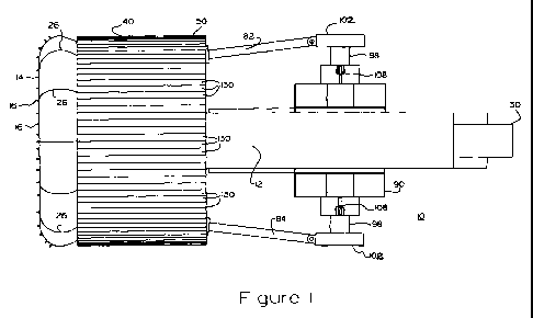
is Figure 1 shows an illustration of a plan view of the TBM to which
this invention has been applied;
Figure 2 is a sectional elevational view of the TBM shown in
Figure 1;
Figure 3 is a sectional view taken at Section 3.3 shown in Figure 2
20 showing the expanding stabilizer of this invention;
3
SUBSTITUTE SHEET (RULE 26)

CA 02774492 2011-12-23
WO 2010/003213 PCT/CA2009/000107
Figure 4 is a sectional elevational view taken at Section 4.4 of
Figure 2 showing the tunnel wall gripper mechanism of this invention;
Figure 5 is a representation of the receptacles in the surface of the
expanding stabilizer of this invention;
Figure 6 is a sectional view of the tunneling machine stabilizing
member as per this invention.
DESCRIPTION OF THE PREFERRED EMBODIMENT
Referring now to the drawings, Figures 1 and 2 show the TBM 10
to to which this invention has been applied. The TBM has a frame structure
12 (sometimes referred to as the main beam) on which most components
involved in the tunneling operations are mounted.
At the very front of the TBM 10 is mounted a rotating head 14
which carries a series of wheels 16 rotatably mounted in bearings (not
is shown) for contacting the tunnel face. Wheels 16 are made from a hard
substance and have a sharp profile to spall the surface of the tunnel face.
The materials selected for the wheels 16 tend to fracture rather than bend
when subjected to lateral forces. For this reason, it is imperative that the
rotating head 14 remains in the center of the tunnel at all times during a
20 tunnel boring operation.
4
RECTIFIED SHEET (RULE 91.1)

PCT/CA2009/000107
CA 02774492 2011-12-23 11 March 2009 11-03-2009
WO 2010/003213 PCT/CA2009/000107
The rotating head 14 is journalled in a suitable bearing 18 which is
securely mounted on frame or main beam 12. This assures that any
transverse forces experienced by the rotating head 14 are transferred to
the frame 12.
The rotating head is driven by a plurality of drive motors 20 two of
which are shown in Figure 2. The drive motors 20 are supplied with
suitable spur gears 22 which engage bull gear 24 which is rigidly attached
to rotating head 14.
Rotating wheel 14 is supplied with a series of loading buckets
io such as 26 which are placed at the periphery of wheel 14 so as to gather
the debris or "muck" spalled from the tunnel rock face during its
excursion from the bottom position of the wheel 14 to its top-most
position on wheel 14. At the top-most position of wheel 14 the bucket
such as the one shown as 26 empties the debris or muck previously
is gathered on the upward excursion of bucket 26 into chute 28 of TBM 10;
onto conveyor 30 which is mounted in the TBM 10 inside frame 12.
Conveyor 30 removes the debris so obtained to a second conveyor or an
awaiting railway car located behind the TBM (not shown).
Mounted on frame 12 just behind the rotating head 14, is a non-
20 rotating stabilizing member 40. Member 40 is more clearly shown in
section in Figure 3. Here the member 40 is shown mounted on frame or
5
SUBSTITUTE SHEET (RULE 26)

PCT/CA2009/000107
CA 02774492 2011-12-23 11 March 2009 11-03-2009
WO 2010/003213 PCT/CA2009/000107
main beam 12 by means of sliding joint 42. The sliding joint 42
comprises a mating box like structure which has an inner box 44 and an
outer box 46 which is firmly secured to stabilizing member 40. Inner box
member 44 is firmly secured to frame 12; in this manner the stabilizing
member is confined to translatory movement in a plane fixed by the
sliding joint 42. It is noted that the conveyor 30 is shown in the interior
of the frame or main beam 12.
It is noted that the exterior diameter of the stabilizing member 40 is
adjustable within certain predetermined limits. Upper shell 50 is movable
io up and down by a pair of actuating piston-cylinders 52 and 54 which are
pivotably attached to main beam 12 at pivot points 56 respectively.
Actuators 52 and 54 are also pivotably attached to upper shell 50 at pivot
points 58 and 60. This permits upper shell to be moved vertically up and
down by actuators 52 and 54 with respect to main beam 12. The upper
1s shell 50 is provided with a pair of sliding joints 62 and 64 at the
junction
of the upper shell 50 and the lower shell 66.
Lower shell 66 is a composite structure having lower side members
68 and 70 being pivotably supported on bottom support member 72 at
pivots 74 and 76 respectively. Bottom support member is usually firmly
20 attached to frame 12 and is incapable of any movement. The lower side
members 68 and 70 are movable about pivots 74 and 76 by a pair of
6
SUBSTITUTE SHEET (RULE 26)

PCT/CA2009/000107
CA 02774492 2011-12-23 11 March 2009 11-03-2009
WO 2010/003213 PCT/CA2009/000107
actuators; thus the diameter of the lower shell 66 is also adjustable within
"certain" limits by means of actuators 78 and 80. This allows the upper
shell 50 and the lower shell 66 of the stabilizing device 40 to be adjusted
(within limits) to accommodate variations in tunnel diameters.
It is noted that in Figure 3, only 3 drive motors 20 are shown for
ease of illustration; there may be more motors driving wheel 24 of TBM
10.
A pair of propulsion actuators 82 and 84 are shown also in Figures
1, 2 and 3. The actuators 82 and 84 are pivotably attached to frame 12 at
to one end thereof and pivotably attached to gripper device 90 more fully
described in Figure 4. Gripper device 90 comprises a pair of actuator
cylinders 92 and 94 in which a pair of gripper pistons 96 and 98 are
respectively received. A pair of grippers 102 are separately actuated and
are mounted on the ends of piston rods 96 and 98 respectively. Grippers
102 are used to contact the walls of the tunnel where it has been driven to
provide a reference position for the TBM 10 as well as providing a
fulcrum for pushing TBM 10 ahead to engage the tunnel face.
The gripper device 90 is slidably mounted on main beam or frame
12 of TBM 10 so as to slide along on tracks 102 and 104 as boring
proceeds.
7
RECTIFIED SHEET (RULE 91.1)

CA 02774492 2011-12-23
WO 2010/003213 PCT/CA2009/000107
A pair of steering actuators 108 and 110 are shown to change the
angle of beam 12 once the grippers 102 have been deployed against the
tunnel walls. Here the actuators 108 and 110 are used to cause movement
of the main beam 12 about gripper trunion assembly 100. Most of the
steering of the TBM is accomplished by the adjustment of actuators 108
and 110 and adjustment of actuators 96 and 98 on the gripper shoes 102.
A rear support cylinder 112 is shown in Figure 2 having piston 114
and sliding pad 116 attached thereto to carry the rear of TBM 10 during
periods of gripper adjustment.
The TBM as illustrated functions as follows: The TBM of Figure 1
is shown with driving arms 82 and 84 fully extended. In order to prepare
the TBM for future movement rear cylinder 112 is actuated until piston
114 and slider 116 make contact with the tunnel surface. Cylinder 112 is
actuated until the desired angle of TBM 10 in the tunnel is achieved. At
this time grippers 102 are retracted and propulsion actuators 82 and 84
are withdrawn to pull gripper device 90 ahead on slides 104 to the
position in Figure 2.
At this time grippers 102 are actuated to contact the tunnel walls
and grippers 102 are set in their working position. Propulsion cylinders
are then actuated to push the rotating head against the tunnel face to
continue the boring operation. It is understood that steering devices 108
8
RECTIFIED SHEET (RULE 91.1)

CA 02774492 2011-12-23
WO 2010/003213 PCT/CA2009/000107
and 110 have been adjusted to be set at the desired angle of TBM 10 in
the tunnel so that the steering of TBM 10 is maintained. Some steering
(trim) is obtained through the adjustment of devices 52, 54, 78 and 80 of
stabilizer 40.
Stabilizer 40 is supplied with adjustable upper shell 50 and
adjustable lower shell 66. The upper shell is movable by actuating
actuators 52 and 54 as shown in Figure 3. Because stabilizing member 40
is so long (maybe 3-4 meters) a second set of actuators may be used in
Figure 2 having pivot points 60.
Mounted on the exterior surface of top shell 50 of stabilizer 40 is a
series of longitudinally extending members 130.
Members 130 are usually steel angles and form a series of
receptacles 132 on top shell 50 of stabilizer 40. The receptacles 132 in
this instance are rectangular in cross section but may be of any desired
shape.
In this instance the receptacles 132 are formed by "L" shaped angle
members welded or secured to top shell 50 of the stabilizer 40. The
shape of the resulting receptacles 132 is dictated by the shape of members
130. The members 130 extend the entire length of the stabilizer 40 thus
the receptacles 132 are of the same length as members 130.
9
SUBSTITUTE SHEET (RULE 26)

CA 02774492 2011-12-23
WO 2010/003213 PCT/CA2009/000107
In operation the TBM functions as follows. The grippers
102 contact the tunnel walls with the propulsion actuators 82 and 84
retracted as shown in Figure 2. Great force is exerted on the tunnel walls
by the actuation of grippers 102. The actuators 96, 98, 110 and 108 on
gripper device 90 are set to orient the TBM in the desired direction.
Rotating head 14 is now stabilized for a tunnel boring operation. The
members 130 secured to top shell 50 contact the surface of the tunnel
with considerable force.
Each receptacle 132 is filled with a "roof support" member 134
1o which has been previously fed into the receptacles 130 by a laborer on the
scene. The roof support members 134 are "extruded" from the
receptacles 132 as the TBM 10 moves ahead in the tunnel boring process.
It is important that the members 134 do not form a joint in the
tunnel roof as the boring process proceeds but that the roof supporting
members 134 form staggered joints in the roof as the TBM moves ahead.
At predetermined intervals depending on the stability exhibited by
the tunnel roof, roof supports in the form of tunnel arch members 140 or
complete tunnel rings 142 may be installed as to support the extruded
tunnel roof members 134 against the surface of the tunnel roof as shown
in Figure 6. These supporting rings 142 should be installed as quickly as
possible after the TBM 10 moves ahead.
RECTIFIED SHEET (RULE 91.1)

CA 02774492 2011-12-23
WO 2010/003213 PCT/CA2009/000107
Many modifications and other embodiments of the invention will
come to the mind of one skilled in the art having the benefit of the
teachings presented in the foregoing descriptions and the associated
drawings. Therefore, it is understood that the invention is not to be
limited to the specific embodiments disclosed, and that the modifications
and embodiments are intended to be included within the scope of the
dependent claims.
15
11
SUBSTITUTE SHEET (RULE 26)

Representative Drawing
A single figure which represents the drawing illustrating the invention.
Administrative Status

2024-08-01:As part of the Next Generation Patents (NGP) transition, the Canadian Patents Database (CPD) now contains a more detailed Event History, which replicates the Event Log of our new back-office solution.

Please note that "Inactive:" events refers to events no longer in use in our new back-office solution.

For a clearer understanding of the status of the application/patent presented on this page, the site Disclaimer , as well as the definitions for Patent , Event History , Maintenance Fee  and Payment History  should be consulted.

Event History

Description Date
Application Not Reinstated by Deadline 2015-01-30
Time Limit for Reversal Expired 2015-01-30
Inactive: Abandon-RFE+Late fee unpaid-Correspondence sent 2014-01-30
Deemed Abandoned - Failure to Respond to Maintenance Fee Notice 2014-01-30
Inactive: Cover page published 2012-06-06
Correct Applicant Requirements Determined Compliant 2012-05-03
Inactive: Inventor deleted 2012-05-03
Inactive: Notice - National entry - No RFE 2012-05-03
Correct Applicant Requirements Determined Compliant 2012-05-02
Application Received - PCT 2012-05-02
Inactive: First IPC assigned 2012-05-02
Inactive: IPC assigned 2012-05-02
National Entry Requirements Determined Compliant 2012-04-23
Application Published (Open to Public Inspection) 2010-01-14

Abandonment History

Abandonment Date Reason Reinstatement Date
2014-01-30

Maintenance Fee

The last payment was received on 2012-04-23

Note : If the full payment has not been received on or before the date indicated, a further fee may be required which may be one of the following

  • the reinstatement fee;
  • the late payment fee; or
  • additional fee to reverse deemed expiry.

Please refer to the CIPO Patent Fees web page to see all current fee amounts.

Fee History

Fee Type Anniversary Year Due Date Paid Date
Basic national fee - standard 2011-12-23
Reinstatement (national entry) 2011-12-30
MF (application, 2nd anniv.) - standard 02 2011-01-31 2012-03-08
MF (application, 4th anniv.) - standard 04 2013-01-30 2012-04-23
MF (application, 3rd anniv.) - standard 03 2012-01-30 2012-04-23
Owners on Record

Note: Records showing the ownership history in alphabetical order.

Current Owners on Record
MICHAEL P. MCNALLY
Past Owners on Record
None
Past Owners that do not appear in the "Owners on Record" listing will appear in other documentation within the application.
Documents

To view selected files, please enter reCAPTCHA code :


To view images, click a link in the Document Description column. To download the documents, select one or more checkboxes in the first column and then click the "Download Selected in PDF format (Zip Archive)" or the "Download Selected as Single PDF" button.

List of published and non-published patent-specific documents on the CPD .

If you have any difficulty accessing content, you can call the Client Service Centre at 1-866-997-1936 or send them an e-mail at CIPO Client Service Centre.


Document
Description 
Date
(yyyy-mm-dd) 
Number of pages   Size of Image (KB) 
Drawings 2011-12-23 5 131
Description 2011-12-23 11 356
Abstract 2011-12-23 1 55
Claims 2011-12-23 4 108
Representative drawing 2012-06-06 1 9
Cover Page 2012-06-06 1 40
Notice of National Entry 2012-05-03 1 194
Reminder - Request for Examination 2013-10-01 1 117
Courtesy - Abandonment Letter (Request for Examination) 2014-03-27 1 164
Courtesy - Abandonment Letter (Maintenance Fee) 2014-03-27 1 171
PCT 2011-12-23 11 495
PCT 2011-12-30 1 38
Correspondence 2011-12-30 2 78
Fees 2012-03-08 1 30
Fees 2012-04-23 1 34