Note: Descriptions are shown in the official language in which they were submitted.
CA 02774979 2012-03-21
WO 2011/097610 PCT/US2011/024008
FLOW ENHANCEMENT DEVICES FOR ETHYLENE
CRACKING COILS
FIELD OF THE DISCLOSURE
[0001] Embodiments disclosed herein relate generally to the cracking
(pyrolysis) of
hydrocarbons, and to a heat exchanger and processes for effecting the cracking
of the
hydrocarbons at higher selectivity and longer run times.
BACKGROUND
[0002] Heat exchangers are used in a variety of applications to heat or cool
fluids
and/or gases, typically by means of indirect heat transfer through different
intervening
layers of heat exchange tubes. For example, heat exchangers may be used in air
conditioning systems, refrigeration systems, radiators, or other similar
systems used
for heating or cooling, as well as in processing systems such as geothermal
energy
production. Heat exchangers are particularly useful in petroleum hydrocarbon
processing as a means to facilitate processing reactions using less energy.
Delayed
cokers, vacuum heaters, and cracking heaters are heat exchange devices
commonly
used in petroleum hydrocarbon processing.
[0003] Numerous configurations for heat exchangers are known and used in the
art.
For example, a common configuration for heat exchangers is a shell and tube
heat
exchanger, which includes a cylindrical shell housing a bundle of parallel
pipes. A
first fluid passes through the pipes while a second fluid passes through the
shell,
around the pipes, such that heat exchanges between the two fluids. In some
shell and
tube configurations, baffles are arranged throughout the shell and around the
tubes so
that the second fluid flows in a particular direction to optimize heat
transfer. Other
configurations for heat exchangers include fired heaters, double-pipe, plate,
plate-fin,
plate-and-frame, spiral, air-cooled, and coil heat exchangers, for example.
Embodiments disclosed herein relate generally to heat exchange tubes used
within a
heat exchange device.
1
CA 02774979 2012-03-21
WO 2011/097610 PCT/US2011/024008
[0004] Generally, the heat transfer rate of a heat exchange tube may be
represented by
the convection equation: Q = UAAT, wherein Q is the heat transferred per unit
time,
A is the area available for the flow of heat, AT is the temperature difference
for the
entire heat exchanger, and U is the overall heat transfer coefficient based on
the area
available for the flow of heat, A.
[0005] It is well known in the art that the rate of heat transfer, Q, may be
increased by
increasing the area available for the flow of heat, A. Thus, a commonly used
method
for increasing the amount of heat transfer is to increase the amount of
surface area in
the heat exchange tube. One such method involves using multiple small diameter
heat
exchange tubes rather than a single larger diameter heat exchange tube. Other
methods of increasing the heat transfer area of the tube wall include adding a
variety
of patterns, fins, channels, ridges, grooves, flow enhancement devices, etc.
along the
tube wall. Such surface variations may also indirectly increase the heat
transfer area
by creating turbulence in the fluid flow. Specifically, turbulent fluid flow
allows for a
higher percentage of fluid to contact the tube wall, thereby increasing the
heat transfer
rate.
[0006] For example, U.S. 3,071,159 describes a heat exchanger tube having an
elongated body with several members extending there from, inserted within the
heat
exchanger tube, such that fluid is channeled close to the wall of the heat
exchanger
tube and the fluid has a turbulent flow. Other heat exchange tubes with
patterns,
including fins, ribs, channels, grooves, bulges, and/or inserts along the tube
wall are
described in, for example, U.S. 3,885,622, U.S. 4,438,808, U.S. 5,203,404,
U.S.
5,236,045, U.S. 5,332,034, U.S. 5,333,682, U.S. 5,950,718, U.S. 6,250,340,
U.S.
6,308,775, U.S. 6,470,964, U.S. 6,644,358, and U.S. 6,719,953.
[0007] It is also known in the art that the heat transfer coefficient, U, is
largely a
function of the thermal conductivity of the heat exchange tube material, the
geometric
configuration of the heat exchange tube, and flow conditions of fluid within
and
around the heat exchange tube. These variables are frequently interrelated,
and thus,
they may be considered in conjunction with one another. In particular, the
geometric
configuration of the heat exchange tube affects flow conditions. Poor flow
conditions
may result in fouling, which is the build up of undesirable deposits on the
walls of the
heat exchange tube. Increased amounts of fouling impede the thermal
conductivity of
the heat exchange tube. Thus, heat exchange tubes are often geometrically
configured
2
CA 02774979 2012-03-21
WO 2011/097610 PCT/US2011/024008
to increase fluid flow velocity and encourage turbulence in the fluid flow as
a way to
break up and prevent fouling.
[0008] In addition to impeding the thermal conductivity of the heat exchange
tube, an
increased amount of fouling may also create a pressure drop throughout the
tube.
Pressure drops in heat exchange tubes may result in increased processing costs
required to restore the pressure within the tube. Furthermore, pressure drops
may
limit the fluid flow rate, thereby reducing the heat transfer rate.
[0009] As described above, adding various patterns and inserts to a heat
exchanger
tube wall are commonly implemented methods of increasing the heat transfer
area and
providing a more turbulent fluid flow, and thereby increasing the heat
transfer rate of
a heat exchanger tube. However, the addition of such mechanical modifications
often
requires higher material costs, expensive manufacturing procedures, and
increased
energy costs (including heating more tube material). Additionally, inserts,
fins, and
the like may cause spalling in certain applications, such as in cracking
heaters or
delayed cokers.
[0010] Ethylene is produced worldwide in large quantities, primarily for use
as a
chemical building block for other materials. Ethylene emerged as a large
volume
intermediate product in the 1940s when oil and chemical producing companies
began
separating ethylene from refinery waste gas or producing ethylene from ethane
obtained from refinery byproduct streams and from natural gas.
[0011] Most ethylene is produced by thermal cracking of ethylene with steam.
Hydrocarbon cracking generally occurs in fired tubular reactors in the radiant
section
of the furnace. In a convection section, a hydrocarbon stream may be preheated
by
heat exchange with flue gas from the furnace burners, and further heated using
steam
to raise the temperature to incipient cracking temperatures, typically 500-680
C
depending on the feedstock.
[0012] After preheating, the feed stream enters the radiant section of the
furnace in
tubes referred to herein as radiant coils. It should be understood that the
method
described and claimed can be performed in ethylene cracking furnaces having
any
type of radiant coils. In the radiant coils, the hydrocarbon stream is heated
under
controlled residence time, temperature and pressure, typically to temperatures
in the
range of about 780-895 C for a short time period. The hydrocarbons in the feed
stream are cracked into smaller molecules, including ethylene and other
olefins. The
3
CA 02774979 2012-03-21
WO 2011/097610 PCT/US2011/024008
cracked products are then separated into the desired products using various
separation
or chemical-treatment steps.
[0013] Various byproducts are formed during the cracking process. Among the
byproducts formed is coke, which can deposit on the surfaces of the tubes in
the
furnace. Coking of the radiant coils reduces heat transfer and the efficiency
of the
cracking process as well as increasing the coil pressure drop. Therefore,
periodically,
a limit is reached and decoking of the furnace coils is required.
[00141 As decoking causes a disruption in production and thermal cycling of
equipment, very long run lengths are desirable. Various methods have been
devised to
extend radiant coil run lengths. These include chemical additives, coated
radiant
tubes, mechanical devices that change flow patterns, as well as other methods.
[0015] The mechanical devices or more generally radiant coil flow enhancement
devices have been most successful in extending run lengths. These devices
increase
run length by changing flow patterns to a "desirable flow pattern" in the
radiant tube
in order to: increase heat transfer rates; reduce the thickness of the
stagnant film along
the tube wall and thus limiting reactions that cause coking of the tube; and
improve
the radial temperature profile within the radiant tube.
[0016] However, these devices have a significant drawback. Use of these
devices
causes an increase in radiant coil pressure drop, which negatively impacts the
yield of
valuable cracking products. This loss of yield has a significant impact on
operating
economics and is therefore a significant limitation.
SUMMARY OF THE CLAIMED EMBODIMENTS
[0017] The intent of the present invention is to overcome the limitation
caused by loss
of yield by locating the chosen radiant coil flow enhancement device(s) in a
strategic
position(s) in the radiant coil. Until now many radiant coil flow enhancement
devices
have been used throughout the coil or at least in the entire length of one
pass of the
coil. Others have been specifically located, however, the location has been
arbitrary or
standard. This invention seeks to locate these devices strategically to
maximize their
impact and minimize the additional pressure drop created.
4
CA 02774979 2012-03-21
WO 2011/097610 PCT/US2011/024008
[0018] In one aspect, embodiments disclosed herein relate to a method of
manufacturing a heat exchange device having at least one heat exchange tube,
comprising:
determining a peak heat flux area of the at least one heat exchange tube; and
disposing in the at least one heat exchange tube an flow enhancement device
for creating a desirable flow pattern in a process fluid flowing through the
at least one heat exchange tube;
wherein the flow enhancement device is disposed in the at least one heat
exchange tube upstream of or at the determined peak heat flux area of the
at least one heat exchange tube.
[0019] In another aspect, embodiments disclosed herein relate to a method of
retrofitting a heat exchange device having at least one heat exchange tube,
comprising:
determining a peak heat flux area of the at least one heat exchange tube; and
replacing at least a portion of the at least one heat exchange tube upstream
of
the determined peak heat flux area with a flow enhancement device for
creating a desirable flow pattern in a process fluid flowing through the at
least one heat exchange tube.
[0020] In another aspect, embodiments disclosed herein relate to a heat
exchange
device, comprising :
at least one heat exchange tube; and
a flow enhancement device disposed in the at least one heat exchange tube for
creating a desirable flow pattern in a process fluid flowing through the at
least one heat exchange tube;
wherein the flow enhancement device is disposed in the at least one heat
exchange tube upstream of or at a determined peak heat flux area of the at
least one heat exchange tube.
CA 02774979 2012-03-21
WO 2011/097610 PCT/US2011/024008
100211 In another aspect, embodiments disclosed herein relate to a process for
producing olefins, the process comprising:
passing a hydrocarbon through a heat exchange tube in a radiant heating
chamber at conditions to effect pyrolysis of the hydrocarbon, the heat
exchange tube having an flow enhancement device disposed therein for
creating a desirable flow pattern of the hydrocarbon flowing through the
heat exchange tube;
wherein the flow enhancement device was selectively disposed in the at least
one heat exchange tube upstream of or at a determined peak heat flux area
of the at least one heat exchange tube.
[0022[ Other aspects and advantages will be apparent from the following
description
and the appended claims.
BRIEF DESCRIPTION OF DRAWINGS
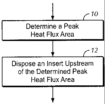
[0023] Figure 1 illustrates a method for manufacturing a heat exchange device
according to embodiments disclosed herein.
[00241 Figure 2 illustrates a simplified cross-section of a typical prior art
pyrolysis
heater.
[0025] Figure 3 is a graph illustrating a surface heat flux profile throughout
the
elevation of a pyrolysis heater.
100261 Figure 4 is a graph illustrating a surface metal temperature profile
throughout
the elevation of a pyrolysis heater.
100271 Figure 5 illustrates a method for retrofitting a heat exchange device
according
to embodiments disclosed herein.
[00281 Figure 6 illustrates a radiant coil of a heat exchange device according
to
embodiments disclosed herein.
[0029] Figure 7 illustrates a method for manufacturing a heat exchange device
according to embodiments disclosed herein.
[00301 Figure 8 illustrates a method for manufacturing a heat exchange device
according to embodiments disclosed herein.
100311 Figures 9A and 913 illustrates a radiant coil insert useful in
embodiments
disclosed herein.
6
RECTIFIED SHEET
CA 02774979 2012-03-21
WO 2011/097610 PCT/US2011/024008
DETAILED DESCRIPTION
[00321 In one aspect, embodiments herein relate to the cracking (pyrolysis) of
hydrocarbons. In other aspects, embodiments disclosed herein relate to a heat
exchanger and processes for effecting the cracking of the hydrocarbons at
higher
selectivity and longer run times.
[00331 Radiant coil flow enhancement devices, as mentioned above, are used to
promote desirable flow profiles within the radiant coil to improve heat
transfer,
reduce coking, and enhance radial temperature profiles. Such devices are
currently
placed throughout the entire length of the radiant coil or distributed
throughout the
length of the coil, such as at a given length interval.
[00341 It has now been surprisingly discovered that selective placement of
radiant
coil flow enhancement devices at a location upstream of or at a peak heat flux
area of
a radiant coil or a radiant coil pass may provide for one or more of the
following as
compared to prior radiant coil flow enhancement device placement methods: i)
an
increased or maximized selectivity and yields to valuable olefins; ii) an
extended
heater run length and capacity; iii) a minimized or decreased number of flow
enhancement devices used in a radiant coil; and iv) a minimized or decreased
pressure
drop through a radiant coil.
[0035) As used herein, placement "upstream" of or at a peak heat flux area
refers to
locating a flow enhancement device in a radiant coil tube such that the flow
profile
resulting from the device extends through the peak heat flux area of the
radiant coil.
One skilled in the art would recognize that the flow pattern induced by the
radiant coil
flow enhancement devices exists in the device and extends only for a limited
distance
after the end of the device,,and merely placing a flow enhancement device in a
coil
may not result in the desired flow pattern extending through the peak heat
flux area.
The placement of the device relative to the peak heat flux area is selected,
according
to embodiments disclosed herein, such that the desired flow zone extends
through the
peak heat flux area, and such placement may depend upon a number of factors
including the type and size of the radiant coil flow enhancement device (axial
length
of the flow enhancement device, number of flow passages through the flow
7
CA 02774979 2012-03-21
WO 2011/097610 PCT/US2011/024008
enhancement device, twist angle(s), etc.), the flow rate of hydrocarbons
and/or steam
through the coil, and coil diameter, among others.
[00361 Referring now to Figure 1, a method for manufacturing a heat exchange
device having at least one heat exchange tube is illustrated. In step 10, for
a given
heat exchange device or heat exchanger design, a heat flux profile for the
heat
exchange device is determined. For example, a furnace (a type of heat exchange
device useful for pyrolysis of hydrocarbons) may have a particular design,
including a
number of burners, burner location, types of burners, etc. The furnace will
thus
provide a particular flame profile (radiant heat) and a combustion gas
circulation
profile (convective heat) based on the furnace design, allowing for the
determination
of the heat flux profile for the furnace. Due to the radiant and convective
driving
forces, the heat flux profile will vary over the length or height of the
furnace, in
virtually all instances, and the determined profile will have one or more peak
heat flux
elevations (i.e., an elevation in the furnace where the heat flux is at a
maximum). In
step 12, based on the determined heat flux profile, a flow enhancement device
may be
disposed in the at least one heat exchange tube upstream of or at the
determined peak
heat flux area to promote a desirable flow pattern through the determined peak
heat
flux area.
[00371 As an example of the method for manufacturing a heat exchange device
having at least one heat exchange tube, reference is made to Figures 1-3 of U.
S.
Patent No. 6,685,893, illustrated herein as Figures 2-4. A cross-section of a
typical
prior art pyrolysis heater is illustrated in Figure 2. The heater has a
radiant heating
zone 14 and a convection heating zone 16. Located in the convection heating
zone 16
are the heat exchange surfaces 18 and 20 which in this case are illustrated
for
preheating the hydrocarbon feed 22. This zone may also contain heat exchange
surface for producing steam. The preheated feed from the convection zone is
fed at 24
to the heating coil generally designated 26 located in the radiant heating
zone 14. The
cracked product from the heating coil 26 exits at 30. The heating coils may be
any
desired configuration including vertical and horizontal coils as are common in
the
industry.
[00381 The radiant heating zone 14 comprises walls designated 34 and 36 and
floor or
hearth 42. Mounted on the floor are the vertically firing hearth burners 46
which are
directed up along the walls and which are supplied with air 47 and fuel 49.
Usually
8
CA 02774979 2012-03-21
WO 2011/097610 PCT/US2011/024008
mounted in the walls are the wall burners 48 which are radiant-type burners
designed
to produce flat flame patterns which are spread across the walls to avoid
flame
impingement on the coil tubes.
[00391 In step 10 of the method of Figure 1, the heat flux profile for the
heater is
determined. Figure 3 shows results of step 10, illustrating a typical surface
heat flux
profile for the heater as illustrated in Figure 2 for two operational modes,
with both
the hearth burners and wall burners being on in one case and with the hearth
burners
being on and the wall burners being off in the other case. Figure 4 shows the
tube
metal temperature determined under the same conditions. These figures show low
heat flux and low metal temperatures in both the lower part of the firebox and
the
upper part of the firebox and show a large difference between the minimum and
maximum of the temperature or the heat flux.
[00401 The peak heat flux for both operational modes is determined to occur at
an
elevation of approximately 5 meters. In step 12, a radiant coil flow
enhancement
device may be disposed in one or more heat exchange tubes of coil 26 upstream
of or
at the peak heat flux elevation, above or below the 5 meter elevation
depending upon
the flow direction, such that the desirable flow zone generated by the flow
enhancement device extends through the peak heat flux area of the one or more
tubes
or tube passes.
[00411 Referring now to Figure 5, a method for retrofitting an existing heat
exchange
device having at least one heat exchange tube is illustrated. In step 50, for
a given
heat exchange device or heat exchanger design, a heat flux profile for the
heat
exchange device is determined. For example, a furnace (a type of heat exchange
device useful for pyrolysis of hydrocarbons) may have a particular design,
including a
number of burners, burner location, types of burners, etc. The furnace will
thus
provide a particular flame profile (radiant heat) and a combustion gas
circulation
profile (convective heat) based on the furnace design, allowing for the
determination
of the heat flux profile for the furnace. Due to the radiant and convective
driving
forces, the heat flux profile will vary over the length or height of the
furnace, in
virtually all instances, and the determined profile will have one or more peak
heat flux
elevations (i.e., an elevation in the furnace where the heat flux is at a
maximum). In
step 52, based on the determined heat flux profile, at least a portion of at
least one
9
CA 02774979 2012-03-21
WO 2011/097610 PCT/US2011/024008
heat exchange tube upstream of or at the determined peak heat flux area is
replaced
with a flow enhancement device for creating the desired flow pattern.
[0042] The heat exchange coil or coils disposed in heat exchange device may
make
multiple passes through the heat transfer area. For example, a heating coil
26, as
illustrated in the furnace of Figure 2, may make one or more passes through
radiant
heating zone 14. Figure 6 illustrates a heat exchange coil 126 having four
passes
through the radiant heating zone, for example, where the hydrocarbon flow
enters the
first heating tube at 128 and traverses through the multiple passes and exits
the coil at
130. The heat exchange coil 126 may be disposed in a furnace having a
determined
peak heat flux area corresponding to that illustrated by area 132. Radiant
coil flow
enhancement device may be disposed in one, two, or more of the tube passes
through
the heat exchange column, where the flow enhancement device(s) are disposed
upstream of or at the determined peak heat flux area 132 according to
embodiments
disclosed herein. As illustrated in Figure 6, radiant coil flow enhancement
device 134
are disposed in each of the tube passes upstream of or at the peak heat flux
area as
based on the indicated flow direction.
[00431 As mentioned above, the flow pattern induced by the radiant coil flow
enhancement device only extends for a limited distance, and the placement of
the flow
enhancement device relative to the peak heat flux area may be selected,
according to
embodiments disclosed herein, such that the desirable flow zone extends
through the
peak heat flux area. The placement may depend upon a number of factors
including
the type and size of the radiant coil flow enhancement device (axial length of
the flow
enhancement device, number of flow passages through the flow enhancement
device,
twist angle(s), etc.), the flow rate of hydrocarbons and/or steam through the
coil, and
coil diameter, among others.
[00441 In some embodiments, the method of manufacturing or retrofitting a heat
exchange device may include additional steps to select a suitable or optimal
location
of the flow enhancement device. Referring now to Figure 7, a method for
manufacturing a heat exchange device having at least one heat exchange tube is
illustrated. Similar to the method of Figure 1, in step 710, for a given heat
exchange
device or heat exchanger design, a heat flux profile for the heat exchange
device is
determined along with the peak heat flux area. In step 720, a length of the
desirable
flow pattern zone resulting from placement of a given flow enhancement device
in a
CA 02774979 2012-03-21
WO 2011/097610 PCT/US2011/024008
heat exchange tube may be determined. This length may then be used in step 730
to
select a distance upstream of the determined peak heat flux area to dispose
the flow
enhancement device in the at least one heat exchange tube such that the
desirable flow
pattern zone extends through the peak heat flux area. The flow enhancement
device
may then be disposed at the selected distance upstream of or at the determined
peak
heat flux area in step 740.
[0045] As noted above, the length of the desirable flow pattern zone may vary
based
upon flow enhancement device design, among other factors. Referring again to
Figure 3, assuming upward fluid flow, a flow enhancement device having a
determined desirable flow pattern zone length of 3 meters may be located
anywhere
from about 2 meters to about 4.5 meters to result in a desirable flow pattern
zone
extending through the peak heat flux area, as illustrated by lines 3A and 3B,
respectively. The selected distance may depend upon tube location and design,
such
as having to account for bends in the coil and coil support structures, among
other
factors.
[0046] While locating a flow enhancement device within this range may result
in
acceptable performance improvements, it may additionally be desired to
maximize the
heat flux over the determined length of the desirable flow pattern zone.
Referring now
to Figure 8, in step 810, for a given heat exchange device or heat exchanger
design, a
heat flux profile for the heat exchange device is determined along with the
peak heat
flux area. In step 820, a length of the desirable flow pattern zone resulting
from
placement of a given flow enhancement device in a heat exchange tube may be
determined. This length may then be used in step 830 to determine a distance
upstream of the determined peak heat flux area to dispose the flow enhancement
device in the at least one heat exchange tube to maximize the heat flux over
the
determined length of the desirable flow pattern zone. The flow enhancement
device
may then be disposed at the determined distance upstream of or at the
determined
peak heat flux area in step 840.
[0047] Referring again to Figure 3, and again assuming upward fluid flow, a
flow
enhancement device having a determined desirable flow pattern zone length of 3
meters may be located anywhere from about 2 meters to about 4.5 meters.
Determination of the distance to maximize heat flux in step 830 may indicate
that
placement of the flow enhancement device at an elevation of approximately 3
meters
11
CA 02774979 2012-03-21
WO 2011/097610 PCT/US2011/024008
may maximize the heat flux over the determined length of the desirable flow
pattern
zone. Although not illustrated, a similar analysis may be performed for flow
enhancement device having different determined desirable flow pattern zone
lengths.
[00481 It may be desired to maximize the heat flux in some embodiments, as
described above. It is additionally noted that the performance of a heat
exchange
device may not rest solely with the heat transfer attained. For example,
performance
of a furnace used for pyrolysis of hydrocarbons may be scrutinized based on
various
operating parameters such as pressure drop through the heating coil(s),
selectivity
and/or yield to a reaction product such as olefins, fouling or coking rates of
the radiant
surfaces (heater run length before shutting down), and cost (number of flow
enhancement devices, for example), among others. Referring to Figures 7 and 8,
one
or more of steps 710, 720, and 730 (810, 820, and 830) may be repeated through
iterations (750, 850) to optimize one or more of the heat flux over the length
of the
desirable flow pattern zone, the length of the desirable flow pattern zone, a
design of
the flow enhancement device, and an operating parameter of the heat exchange
device.
[00491 Flow enhancement devices, as mentioned above, may vary in design. Flow
enhancement devices may divide the fluid flow into two, three, four, or more
passages,-can have a twisted angle of the flow enhancement device baffle in
the range
from about 100 to 360 or more, and may vary in length from about 100 mm to
the
full tube length in some embodiments, and from about 200 mm to the full tube
length
in other embodiments. In other embodiments, the length of the flow enhancement
device may be in the range from about 100 mm to about 1000 mm; or from about
200
mm to about 500 mm in yet other embodiments. The thickness of the baffle may
be
approximately the same as the coil tube in some embodiments. Preferably, the
baffle
and the surface of the coil piece holding it in place has the shape of a
concave circular
arc or a similar shape to minimize eddy formation through the passages,
reducing
flow resistance and pressure drop. The flow enhancement devices may be made,
for
example, by means of smelting the raw material in the vacuum condition and
precision casting, where the flow enhancement device mold is inserted into the
coil
piece and the required amount of alloy is poured into the mold to form the
baffle and
the mold burns away in the process. The flow enhancement device can be
installed by
a cut-and-paste approach into new or existing tubes. Alternately the flow
12
CA 02774979 2012-03-21
WO 2011/097610 PCT/US2011/024008
enhancement devices can be formed by adding a weld bead or other helical fin
to a
standard bare tube. This weld bead can be continuous or discontinuous and may
or
may not extend the length of the radiant tube.
[0050] One example of a radiant coil flow enhancement device is illustrated in
Figures 9A (profile view) and 9B (end view). The radiant coil flow enhancement
device illustrated divides the fluid flow into two flow paths traversing the
length of
the flow enhancement device. The coil includes a baffle having a twisted angle
of
approximately 180 .
[0051] As mentioned above, flow enhancement devices may be useful in furnaces
used for the pyrolysis (cracking) of hydrocarbon feedstocks. The hydrocarbon
feedstock may be any one of a wide variety of typical cracking feedstocks such
as
methane, ethane, propane, butane, mixtures of these gases, naphthas, gas oils,
etc.
The product stream contains a variety of components the concentration of which
is
dependent in part upon the feed selected. In a conventional pyrolysis process,
vaporized feedstock is fed together with dilution steam to a tubular reactor
located
within the fired heater. The quantity of dilution steam required is dependent
upon the
feedstock selected; lighter feedstocks such as ethane require lower steam (0.2
lb./lb.
feed), while heavier feedstocks such as naphtha and gas oils require
steam/feed ratios
of 0.5 to 1Ø The dilution steam has the dual function of lowering the
partial pressure
of the hydrocarbon and reducing the carburization rate of the pyrolysis coils.
[0052] In a typical pyrolysis process, the steam/hydrocarbon feed mixture is
preheated to a temperature just below the onset of the cracking reaction, such
as about
650 C. This preheat occurs in the convection section of the heater. The mix
then
passes to the radiant section where the pyrolysis reactions occur. Generally
the
residence time in the pyrolysis coil is in the range of 0.05 to 2 seconds and
outlet
temperatures for the reaction are on the order of 700 C to 1200 C. The
reactions that
result in the transformation of saturated hydrocarbons to olefins are highly
endothermic, thus requiring high levels of heat input. This heat input must
occur at
the elevated reaction temperatures. It is generally recognized in the industry
that for
most feedstocks, and especially for heavier feedstocks such as naphtha,
shorter
residence times will lead to higher selectivity to ethylene and propylene as
secondary
degradation reactions will be reduced. Further it is recognized that the lower
the
13
CA 02774979 2012-03-21
WO 2011/097610 PCT/US2011/024008
partial pressure of the hydrocarbon within the reaction environment, the
higher the
selectivity.
[0053] In pyrolysis heaters, the rate of fouling (coking) is set by the metal
temperature and its influence on the coking reactions that occur within the
inner film
of the process coil. The lower the metal temperature, the lower the rates of
coking.
The coke formed on the inner surface of the coil creates a thermal resistance
to heat
transfer. In order for the same process heat input to be obtained as the coil
fouls,
furnace firing must increase and outside metal temperature must increase to
compensate for the resistance of the coke layer.
[0054] The peak heat flux areas of the furnace thus limit the overall
performance of
the furnace and the cracking process due to fouling / coking at the high metal
temperatures. Embodiments disclosed herein, disposing flow enhancement devices
at
selected or determined locations within the coil may thus provide numerous
benefits.
The flow patterns induced by the flow enhancement devices through the peak
heat
flux area may decrease or minimize fouling through the portion of the coil
having the
highest metal temperature. As a result of the strategic placement of the flow
enhancement devices, the reduced fouling rate may allow for extended run
times.
Additionally, disposing flow enhancement devices in the coil in limited
locations,
such as only upstream of or at peak heat flux area(s) and not throughout the
entirety of
the coil, pressure drop through the coil may be decreased or minimized, thus
improving one or more of selectivity, yield, and capacity. The longer run
times,
improved selectivity, improved yield and/or improved capacity attainable
according to
embodiments disclosed herein may thus significantly improve the economic
performance of the pyrolysis process.
[0055] While the disclosure includes a limited number of embodiments, those
skilled
in the art, having benefit of this disclosure, will appreciate that other
embodiments
may be devised which do not depart from the scope of the present disclosure.
Accordingly, the scope should be limited only by the attached claims.
14