Note: Descriptions are shown in the official language in which they were submitted.
CA 2775058 2017-02-28
236619
GASIFICATION COOLING SYSTEM HAVING SEAL
BACKGROUND OF THE INVENTION
[0001] The subject matter disclosed herein relates to gasification cooling
systems,
such as radiant syngas coolers, which cool gas from a gasifier.
[0002] Integrated gasification combined cycle (IGCC) power plants are
capable of
generating energy from various hydrocarbon feedstock, such as coal, relatively
cleanly
and efficiently. IGCC technology may convert the hydrocarbon feedstock into a
gas
mixture including carbon monoxide (CO) and hydrogen (H2), e.g., syngas, by
reaction
with steam in a gasifier. These gases may be cooled, cleaned, and utilized as
fuel in a
conventional combined cycle power plant. For example, a radiant syngas cooler
(RSC)
may receive and cool the syngas upstream from a water gas shift reactor and/or
other gas
cleaning units. Unfortunately, the high temperature of syngas entering a
throat of the
RSC can potentially damage heat exchanger tubing and/or the body of the RSC
without
sufficient thermal protection. Furthermore, thermal changes in the RSC can
cause
significant thermal expansion and contraction, which complicate the design for
thermal
protection in the throat of the RSC.
BRIEF DESCRIPTION OF THE INVENTION
[0003] Certain embodiments commensurate in scope with the originally
claimed
invention are summarized below. These embodiments are not intended to limit
the
scope of the claimed invention, but rather these embodiments are intended only
to
provide a brief summary of possible forms of the invention. Indeed, the
invention may
encompass a variety of forms that may be similar to or different from the
embodiments
set forth below.
[0004] In a first embodiment, a system includes a gasification cooling
system having
a housing with an inlet, an outlet, and an interior between the inlet and the
outlet. The
interior has a throat adjacent the inlet, and the throat expands in a flow
direction from
the inlet toward the outlet. The gasification cooling system also has an
annular seal
disposed in the throat of the housing, wherein the annular seal has a bellows.
1
CA 02775058 2012-03-22
WO 2011/037697
PCT/US2010/045185
100051 In a second embodiment, a system includes a gasification cooling
system
having a housing with a gas passage extending in a flow direction lengthwise
along the
housing, a first plurality of thermally insulative bricks disposed about the
gas passage, a
bellows seal disposed about the first plurality of thermally insulative
bricks, and a.
plurality of heat exchanger tubes disposed downstream from the bellows seal.
The
bellows seal is configured to expand and contract in response to thermal
contraction or
expansion of the plurality of heat exchanger tubes.
100061 In a third embodiment a system includes a gasification cooling system
having
a housing with a gas passage extending in a flow direction lengthwise along
the housing
and a first plurality of thermally insulative bricks disposed about the gas
passage. The
gasification cooling system also includes a second plurality of thermally
insulative
bricks disposed about the first plurality of thermally insulative bricks,
wherein the
second plurality of thermally insulative bricks is axially staggered relative
to the first
plurality of thermally insulative bricks, and the second plurality of
thermally insulative
bricks includes an interlocking interface between adjacent bricks. The
gasification
cooling system also includes a thermally insulative liner disposed about the
second
plurality of thermally insulative bricks, a bellows seal disposed about the
thermally
insulative liner, and a thermally insulative material disposed between the
thermally
.insulative liner and the bellows seal. The gasification cooling system
further includes a
plurality of heat exchanger tubes downstream of the bellows seal, wherein the
bellows
seal is configured to expand and contract in the flow direction.
BRIEF DESCRIPTION OF THE DRAWINGS
100071 These and other features, aspects, and advantages of the present
invention will
become better understood when the following detailed description is read with
reference
to the accompanying drawings in which like characters represent like parts
throughout
the drawings, wherein:
1000S1 FIG. 1 is a block diagram of an embodiment of an integrated
gasification
combined cycle (IGCC) power plant including a radiant syngas cooler (RSC);
2
CA 02775058 2012-03-22
WO 2011/037697
PCT/US2010/045185
100091 FIG. 2 is across-sectional side view of an embodiment of the RSC of
FIG. I;
100101 FIG. 3 is a partial cross-sectional view of the RSC of FIG. 2,
illustrating an
embodiment of a refractory system and an annular seal as shown within line 3-3
of FIG.
2;
loom FIG. 4 is a cross-sectional view of an embodiment of an annular seal
including a bellows with outward protruding annular grooves;
100121 FIG. 5 is a cross-sectional view of an embodiment of the annular
seal having
the bellows with outward protruding annular grooves;
100131 FIG. 6 is a cross-sectional view of an embodiment of the annular
seal having
the bellows with inward and outward protruding annular grooves; and
100141 FIG. 7 is a cross-sectional view of an embodiment of the annular
seal having
the bellows with inward protruding annular grooves.
DETAILED DESCRIPTION OF THE INVENTION
100151 One or more specific embodiments of the present invention will be
described
below. In an effort to provide a concise description of these embodiments, all
features
of an actual implementation may not be described in the specification. It
should be
appreciated that in the development of any such actual implementation, as in
any
engineering or design project, numerous implementation-specific decisions must
be
made to achieve the developers' specific goals, such as compliance with system-
related
and business-related constraints, which may vary from one implementation to
another.
Moreover, it should be appreciated that such a development effort might be
complex and
time consuming, but would nevertheless be a routine undertaking of design,
fabrication,
and manufacture for those of ordinary skill having the benefit of this
disclosure.
100161 When introducing elements of various embodiments of the present
invention,
the articles "a," "an," "the," and "said" are intended to mean that there are
one or more
of the elements. The terms "comprising," "including," and "having" are
intended to be
inclusive and mean that there may be additional elements other than the listed
elements.
3
CA 02775058 2012-03-22
WO 2011/037697
PCT/US2010/045185
(00171 As described below, the disclosed embodiments may include an annular
seal
having a bellows, which expands and contracts in response to movement (e.g.,
thermal
expansion and contraction). The bellows may be disposed in a variety of
systems and
devices, such as those found in industrial equipment, power plants, or other
applications.
For example, the annular seal may be mounted within a gasification cooling
system,
such as a radiant syngas cooler (RSC), configured to cool syngas originating
from a
gasifier in an integrated gasification combined cycle (I(3CC) power plant. In.
certain
embodiments, the annular seal may be mounted within a throat region of the RSC
to
block leakage of the syngas into a dome chamber and elsewhere inside the RSC.
For
example, the annular seal may block leakage of the syngas from reaching heat
exchanger
tubing and/or walls of the RSC. As appreciated, the RSC may be subject to
considerable
variations in temperature, which may cause thermal expansion and contraction,
and thus
movement of components, inside the RSC. The bellows of the annular seal
expands and
contracts in response to these movements, thereby maintaining a constant seal
to block
leakage of the syngas. In certain embodiments, the bellows of the annular seal
includes
an alternating diameter that radially increases and decreases in a direction
of syngas flow
through the RSC. In one embodiment, the alternating diameter of the bellows
radially
increases and decreases both greater than and less than a base diameter. In
other
embodiments, the alternating diameter of the bellows radially increases and
decreases
either only less than or only greater than the base diameter. Hovvever, the
bellows may
have other configurations within the scope of the disclosed annular seal.
100181 In certain embodiments, a refractory system may be used in conjunction
with
the annular seal in the RSC to ensure that hot syngas entering the RSC does
not
thermally damage the annular seal. For instance, the refractory system may
include a
variety of refractory materials capable of maintaining their physical and/or
chemical
properties at temperatures substantially above approximately 1000 F. For
example, the
refractory system may include one or more sets of refractory bricks, which
maintain
their predetermined physical shape upon exposure to high temperatures such as
approximately .1000 F to 3000 F (e.g., 28007). For example, the high
temperatures
may be at least up to or greater than approximately 1000 F, I500 F, 2000 F,
2500 F, or
3000 F. These refractory bricks may define an annular shape inside the RSC,
e.g., via
4
CA 02775058 2012-03-22
WO 2011/037697
PCT/US2010/045185
axial, radial, and/or circumferential stacking of the bricks. The refractory
system also
may include one or more layers or liners of thermally insulative material,
e.g., in an
annular shape inside the RSC. The refractory system, in certain embodiments,
may
include a thermally insulative material disposed along the annular seal, a
thermally
insulative liner disposed radially inside the themially insulative material, a
first plurality
of thermally insulative bricks disposed radially inside the thermally
insulative liner, and
a second plurality of thermally insulative bricks disposed radially inside the
first
plurality of thermally insulative bricks. The components of the refractory
system may
cooperate to minimize the surface temperature of the annular seal during
operation of the
RSC. In these embodiments, the refractory system may substantially block heat
transfer
to the annular seal, thereby maintaining the annular seal at a sufficiently
low
temperature. In other words, the refractory system may be used without an
active
cooling system, e.g., heater exchanger tubes, for the annular seal.
100191 FIG. .1 is a diagram of an embodiment of an integrated gasification
combined
cycle (IGCC) system 100 that may be powered by synthetic gas, i.e., syngas.
Elements
of the IGCC system 1(X) may include a fuel source 102, such as a solid feed,
that may be
utilized as a source of energy for the IOCC. The fuel source 102 may include
coal.
petroleum coke, biomass, wood-based materials, agricultural wastes, tars, coke
oven tzzis
and asphalt, or other carbon containing items.
100201 The solid fuel of the fuel source" 02 may be passed to a feedstock
preparation
unit 104. The feedstock preparation unit 104 may, for example, resize or
reshape the
fuel source 102 by chopping, milling, shredding, pulverizing, briquetting, or
palletizing
the fuel source 102 to generate feedstock. Additionally, water, or other
suitable liquids
may be added to the fuel source 102 in the feedstock preparation unit 104 to
create
slurry feedstock. In other embodiments, no liquid is added to the fuel source,
thus
yielding dry feedstock.
[00211 The feedstock may be passed to a gasifier 106 from the feedstock
preparation
unit .104. The gasifier 106 may convert the feedstock into a syngas, e.g., a
combination
of carbon monoxide arid hydrogen. This conversion may be accomplished by
subjecting
the feedstock to a controlled amount of steam and oxygen at elevated
pressures, e.g.,
CA 02775058 2012-03-22
WO 2011/037697
PCT/US2010/045185
from approximately 20 bar to 85 bar, and temperatures, e.g., approximately 700
degrees
Celsius ¨ 1600 degrees Celsius, depending on the type of gasifier 106
utilized. The
gasification process may include the feedstock undergoing a pyrolysis process,
whereby
the feedstock is heated. Temperatures inside the gasifier .106 may range from
approximately 150 degrees Celsius to 700 degrees Celsius during the pyrolysis
process,
depending on the fuel source 102 utilized to generate the feedstock. The
heating of the
feedstock during the pyrolysis process may generate a solid, (e.g., char), and
residue
gases, (e.g., carbon monoxide, hydrogen, and nitrogen). The char remaining
from the
feedstock from the pyrolysis process may only weigh up to approximately 30% of
the
weight of the original feedstock.
100221 A combustion process may then occur in the gasifier 106. The combustion
may include introducing oxygen to the char and residue gases. The char and
residue
eases may react with the oxygen to form carbon dioxide and carbon monoxide,
which
provides heat for the subsequent gasification reactions. The temperatures
during the
combustion process may range from approximately 700 degrees Celsius to 1600
degrees
Celsius. Next, steam may be introduced into the gasifier 106 during a
gasification step.
The char may react with the carbon dioxide and steam to produce carbon
monoxide and
hydrogen at temperatures laming from approximately 800 degrees Celsius to 1100
degrees Celsius. In essence, the gasifier utilizes steam and oxygen to allow
some of the
feedstock to be "burned" to produce carbon monoxide and energy, which drives a
second reaction that converts further feedstock to hydrogen and additional
carbon
dioxide.
100231 In this way, a resultant gas is manufactured by the gasifier 106.
This resultant
gas may include approximately 85% of carbon monoxide and hydrogen, as well as
CH4,
1-IC1, HI', COS, N115, HCN, and .H2S (based on the sulfur content of the
feedstock). This
resultant gas may be termed dirty syngas. The gasifier 106 may also generate
waste,
such as slag 108, which may be a wet ash material. This slag 108 may be
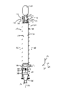
removed from
the gasifier 106 and disposed of, for example, as mad base or as another
building
material. To clean the dirty syngas, a gas cleaning unit 110 may be utilized.
The gas
cleaning unit 110 may scrub the dirty syngas to remove the HC1, HF, COS, HCN,
and
H2S from the dirty syngas, which may include separation of sulfur 111 in a
sulfur
6
CA 02775058 2012-03-22
WO 2011/037697
PCT/US2010/045185
processor 112 by, for example, an acid gas removal process in the sulfur
processor 112.
Furthermore, the gas cleaning unit 110 may separate salts 113 from the dirty
syngas via
a water treatment unit 114 that may utilize water purification techniques to
generate
usable salts 113 from the dirty syngas. Subsequently, the gas from the gas
cleaning unit
110 may include clean syngas, e.g., NH3 (ammonia) and Cl-i4 (methane).
100241 A gas processor 116 may be utilized to remove residual gas components
117
from the clean syngas such as, ammonia and methane, as well as methanol or any
residual chemicals. However, removal of residual gas components 117 from the
clean
syngas is optional, since the clean syngas may be utilized as a fuel even when
containing
the residual gas components 117, e.g., tail gas. At this point, the clean
syngas may
include approximately 1-10% CO (e.g., 3% CO), approximately 30-60% H2 (e.g.,
55%
H2), and approximately 30-60% CO2 (e.g., 40% CO2) and is substantially
stripped of
H2S. This clean syngas may be transmitted to a combustor 120, e.g., a
combustion
chamber, of a gas turbine engine 118 as combustible fuel.
100251 The 1GCC system 100 may further include an air separation unit (ART)
122.
The ASU 122 may operate to separate air into component gases by, for example,
distillation techniques. The ASU 122 may separate oxygen from the air supplied
to it
from a supplemental air compressor 123, and the ART 122 may transfer the
separated
oxygen to the gasifier 106. Additionally the ASO 122 may transmit separated
nitrogen
to a diluent nitrogen (MAN) compressor 124.
100261 The DGAN compressor 124 may compress the nitrogen received from the
ASU 122 at least to pressure levels equal to those in the combustor 120, so as
not to
interfere with the proper combustion of the syngas. Thus, once the DGAN
compressor
124 has adequately compressed the nitrogen to a proper level, the DGAN
compressor
124 may transmit the compressed nitrogen to the combustor 120 of the gas
turbine
engine 118.
100271 As described previously, the compressed nitrogen may be transmitted
from
the DGAN compressor 124 to the combustor 120 of the gas turbine engine 118.
The gas
turbine engine 118 may include a turbine 130, a drive shaft 131 and a
compressor 132,
7
CA 02775058 2012-03-22
WO 2011/037697
PCT/US2010/045185
as well as the combustor 120. The combustor 120 may receive fuel, such as
syngasõ
which mw be injected under pressure from fuel nozzles. This fuel may be mixed
with
compressed air as well as compressed nitrogen from the DGAN compressor 1.24,
and
combusted within combustor 120. This combustion may create hot pressurized
exhaust
gases.
100281 The combustor 120 may direct the exhaust gases towards an exhaust
outlet of
the turbine .130. As the exhaust gases from the combustor 120 pass through the
turbine
130, the exhaust gases may force turbine blades in the turbine 130 to rotate
the drive
shaft 131 along an axis of the gas turbine engine 118. As illustrated, the
drive shaft 131
is connected to various components of the gas turbine engine 118, including
the
compressor 132.
100291 The drive shaft 131 may connect the turbine 130 to the compressor 132
to
form a rotor. The compressor .132 may include blades coupled to the drive
shaft 13.1.
Thus, rotation of turbine blades in the turbine 130 may cause the drive shaft
131
connecting the turbine 130 to the compressor 132 to rotate blades within the
compressor
132. This rotation of blades in the compressor 132 calms the compressor 132 to
compress air received via an air intake in the compressor 132. The compressed
air may
then be fed to the combustor 120 and mixed with fuel and compressed nitrogen
to allow
for higher efficiency combustion. Drive shaft 131 may also be connected to
load 134,
which may be a stationary load, such as an electrical generator for producing
electrical
power, for example, in a power plant. Indeed, load 134 may be any suitable
device that
is powered by the rotational output of the gas turbine engine 118.
100301 The IOCC system 100 also may include a steam turbine engine 136 and a
heat
recovery steam generation (HRSG) system .138. The steam turbine engine 136 may
drive a second load 140. The second load 140 may also be an electrical
generator for
generating electrical power. However, both the first and second loads 134, 140
may be
other types of loads capable of being driven by the gas turbine engine 118 and
steam
turbine engine 136. In addition, although the gas turbine engine 118 and steam
turbine
engine 136 may drive separate loads 134 and 140, as shown in the illustrated
embodiment, the gas turbine engine 118 and steam turbine engine 136 may also
be
8
CA 02775058 2012-03-22
WO 2011/037697
PCT/US2010/045185
utilized in tandem to drive a single load via a single shaft. The specific
configuration of
the steam turbine engine 136, as well as the gas turbine engine 118, may be
implementation-specific and may include any combination of sections.
100311 The system 100 may also include the HRSG 138. Heated exhaust gas from
the gas turbine engine 118 may be transported into the HRSG 138 and used to
heat water
and produce steam used to power the steam turbine engine 136. Exhaust from,
for
example, a low-pressure section of the steam turbine engine 136 may be
directed into a
condenser 142. The condenser 142 may utilize a cooling tower 128 to exchange
heated
water for chilled water. The cooling tower 128 acts to provide cool water to
the
condenser 142 to aid in condensing the steam transmitted to the condenser 142
from the
steam turbine engine 136. Condensate from the condenser 142 may, in turn, be
directed
into the HRSG 138. Again, exhaust from the gas turbine engine 118 may also be
directed into the MSG 138 to heat the water from the condenser 142 and produce
steam.
100321 In combined cycle systems such as 10CC system 100, hot exhaust may flow
from the gas turbine engine 118 and pass to the HRSG 138, where it may be used
to
generate high-pressure, high-temperature steam. The steam produced by the HRSG
138
may then be passed through the steam turbine engine 136 for power generation.
In
addition, the produced steam may also be supplied to any other processes where
steam
may be used, such as to the gasifier 106. The gas turbine engine 118
generation cycle is
often referred to as the "topping cycle," whereas the steam turbine engine 136
generation cycle is often referred to as the "bottoming cycle." By combining
these two
cycles as illustrated in FIG. 1, the ICFCC system 100 may lead to greater
efficiencies in
both cycles. In particular, exhaust heat from the topping cycle may be
captured and
used to generate steam for use in the bottoming cycle.
100331 FIG. 2 is a cross-sectional side view of an embodiment of a radiant
syngas
cooler (RSC) 146 for use with the 10CC system 100 of FIG. I. The RSC may have
an
axial axis 125, a radial axis 126, and a circumferential axis 127. The RSC 146
may
include a vessel 148, which may be made of a suitable material such as ASTM
SA387,
wade 11, class 2. The vessel 148 functions as a housing or outer casing for
the RSC
9
CA 02775058 2012-03-22
WO 2011/037697
PCT/US2010/045185
146, enclosing both an upper region 147 of the RSC 146 as well as a lower
region 149 of
the RSC 146. The upper region 147 of the RSC 146 may include a dome-shaped
portion
150 that includes an inlet 152 extending into a throat 153. The lower region
149
includes an outlet 154. An interior region .156 is defined by the space
between the inlet
152 and the outlet 154. The throat 153, which is adjacent the inlet 152,
expands in a
downstream direction 155 from the inlet 152 toward the outlet 154.
100341 The vessel 148 may also include tubing 158, which may be in the upper
region 147 of the RSC 146. The tubing 158 may include a plurality of conduits
along
the radial axis 126 of the RSC 146 and may run parallel in direction with the
vessel 148
relative to the axial axis 125. Chilled liquid, such as water, may flow
through the tubing
158. Thus, the tubing 158 may act as a heat exchanger within the RSC 146, and
may.
circulate the coolant to an external heat exchanger for removal of heat.
Accordingly, the
tubing 158 may be made of a thermally resistant material suitable for use with
hot
syngas, such as ASTM S13407 UNS 18800 (Ed 2004).
100351 During operation, the syngas generated in the gasifier 106 may
generally -flow
in a downward manner parallel to the tubing 158 as indicated by arrows 160.
That is,
the syngas flows through a gas passage of the RSC .146 that extends in the
flow direction
160 lengthwise along the vessel 148. Accordingly, the syngas enters the RSC
146
through the inlet 152, flows lengthwise through the interior region 156 of the
RSC 146,
and then exits the RSC 146 through the outlet 154. In this manner, the syngas
may
come in contact with the tubing 158 of the RSC 146 and the fluid flowing
through the
tubing 158 may act to cool the syngas as it travels through the RSC 146. One
result of
this cooling process may be the generation of steam in the tubing 158, which
may then
be transmitted to the high pressure drum 145 (see FIG. 1) for collection and
transmission
to the heat recovery steam generator 138.
[00361 The RSC 146 may also include a conduit 162 in the lower region 149 of
the
RSC 146 that may aid in directing the cooled syngas and slag out of the RSC
146. For
example, as the slag 108 (see FIG. 1) exits the conduit 162, the slag 108 may
flow in a
generally downward direction 164 to exit the RSC 146 via a quench cone 166. In
contrast, the cooled syngas may flow in a general upward direction 168 towards
a
CA 02775058 2012-03-22
WO 2011/037697
PCT/US2010/045185
transfer line 170 as the syngas exits the conduit 162. The transfer line 170
may be used
to transmit the syngas to the gas cleaning unit 110 and/or the gas turbine
engine 118.
The raw syngas may corrode elements of the RSC 146, such as the tubing 158
and/or the
inner wall of the vessel 148, if these elements were to come into contact with
the syngas.
Accordingly, a gas inlet 172 may transmit a non-corrosive fluid, such as a
shielding gas
180 (e.g., nitrogen), to the RSC 146. This non-corrosive fluid may flow
generally
downward between the vessel 148 and the tubing 158 of RSC 146 form a
protective
barrier, for example, against syngas migration into the =Mar space between the
tubes
158 and the vessel 148.
[00371 As will be described in more detail below with respect to FIGS. 3-7,
the dome
shaped portion 150 of the upper region 147 of the RSC 146 encloses a dome
chamber
having a unique refractory system and an annular seal. The annular seal is
configured to
block leakage of the hot syngas from an interior chamber to an outer chamber.
In certain
embodiments, the annular seal includes a bellows configured to expand and
contract
with movement (e.g., thermal expansion and contraction) within the RSC 146,
thereby
maintaining a constant seal to block leakage of the syngas. The refractory
system is
configured to thermally block heat transfer from the hot syngas to the annular
seal as
well as the outer chamber. In certain embodiments, the refractory system
includes a
plurality of refractory bricks and insulative layers configured to thermally
shield the
annular seal.
100381 FIG. 3 is a partial cross-sectional view of the RSC 146 taken within
line 3-3
of FIG. 2, illustrating thermal and mechanical control features located in the
dome-
shaped portion 150 of the upper region 147 of the RSC 146. The vessel housing
148
separates an exterior 180 of the RSC 146 from an interior 182 of the RSC 146.
The
interior 182 of the RSC 146 includes a dome chamber 184 (e.g., outer annular
chamber)
and interior chamber 186 (e.g., central volume or syngas passage) separated by
an
interior annular wall assembly 187. In the illustrated embodiment; the wall
assembly
187 includes a refractory system 188 having a plurality of thermally
insulative bricks
189. The illustrated wall assembly 187 also includes an annular seal 190. As
discussed
in detail below, the wall assembly 187 is configured to block heat transfer
and leakage
of syngas from the interior chamber 186 to the dome chamber 184 during
operation of
CA 02775058 2012-03-22
WO 2011/037697
PCT/US2010/045185
the RSC 146. In particular, the refractory system 188 employs the thermally
insulative
bricks 189 (among other insulative features) to reduce heat transfer to the
annular seal
190, thereby maintaining a sufficiently low temperature of the annular seal
190 in the
dome chamber 184. The annular seal 190 blocks leakage of the syngas from the
interior
chamber 186 to the dome chamber 184. Thus, the wall assembly 187 relies on
both the
refractory system 188 and the annular seal 190 to provide a combined bather
against gas
flow and heat transfer associated with. the hot syngas in the dome-shaped
portion 150 of
the upper region 147 of the RSC 146,
100391 The annular seal 190 is disposed about the circumference of the
interior
chamber 186 to block syngas from leaking into the dome chamber 184 during
operation.
The annular seal 190 may be disposed at any location in the throat 153 of dome-
shaped
portion 150 of the housing 148. For example, the annular seal 190 may be
located
completely within a portion 191 of the dome-shaped portion 150, as indicated
by arrow
191. In certain embodiments, the portion 191 may correspond to an upstream
portion of
the dome-shaped portion 150 adjacent the gas inlet 152. For example, the
portion 191
may be less than or equal to approximately 10, 20, 30, 40, or 50 percent of
the dome-
shaped portion 150 at the upstream end adjacent the gas inlet 152. However,
certain
embodiments of the annular seal 190 may be disposed in any suitable location
along the
axial axis 125 upstream of the tubes 158 and downstream of the inlet 152.
100401 In the illustrated embodiment, the refractory system 188 may be used in
conjunction with the annular seal 190 to ensure that hot syngas entering the
RSC 146
from the gasifier 106 does not thermally damage the annular seal 190. The
refractory
system 188 may include a variety of refractory materials capable of
maintaining their
physical and/or chemical properties at temperatures substantially above
approximately
1000 F. For example, the refractory system 188 may include one or more sets of
pre-
sintered refractory bricks 189, which maintain their predetermined physical
shape upon
exposure to high temperatures, such as high temperatures at least up to or
greater than
approximately 1000 F to 3000 F (e.g., 2800 F). For example. the high
temperatures
may be at least up to or greater than approximately 1000T, 1500 F, 2000 F,
2500 F, or
3000 F. Suitable refractory materials for use in the refractory system 188
include
12
CA 02775058 2012-03-22
WO 2011/037697
PCT/US2010/045185
ceramics (e.g., clay or minerals), metals (e.g., titanium, tungsten), cermets
(i.e., ceramic
and metal composites), or other refractory materials (e.g., silica, aluminum
oxide).
100411 The thermally insulative bricks 189 of the refractory system 188 may
include
any number and arrangement of bricks in the axial, radial, and/or
circumferential
directions. These bricks 189 may interlock with one another to resist gas flow
and heat
transfer from the interior chamber 186 toward the dome chamber 184. In the
illustrated
embodiment, the bricks 189 include a first plurality of thermally insulative
bricks 192
and a second plurality of thermally .insulative bricks 194 in a concentric
arrangement
relative to one another. In other words, the first plurality of bricks 192
defines a first
annular wall defined by bricks stacked axially and circumferentially about the
interior
chamber 186. Likewise, the second plurality of bricks 194 defines a second
annular wall
defined by bricks stacked axially and circumferentially about the first
plurality of bricks
192. The first and second annular walls (i.e., defined by bricks 192 and 194)
are
disposed at different diameters, such that the bricks 192 are radially inside
the bricks
194. Together, the first and second plurality of bricks 192 and 194 provide
radial
stacking (e.g., two concentric walls of bricks).
100421 The bricks 189 may include a variety of interlocking features for
retention and
improved resistance to gas flow and heat transfer. As illustrated, the first
plurality of
bricks 192 is axially staggered relative to the second plurality of bricks
194, as indicated
by axial offset or stagger 193. For instance, a lower edge 200 of a brick 202
abuts a
brick 204 at an intersection point 206. However, in other embodiments, the
first
plurality of bricks 192 and the second plurality of bricks 194 may be axially
aligned
with one another. In addition, the bricks 192 and 194 may be staggered in the
circumferential direction about the interior chamber 186. This staggering
helps block
heat transfer and gas flow. As discussed further below, the bricks 192 and 194
may
have any suitable similar or different shape. As illustrated, the bricks 194
including
interlocking interfaces 195 configured to block heat transfer and gas flow in
the radial
direction, as well as provide additional retention of the bricks 194 in the
radial direction.
100431 The bricks 189 may be made of a suitable refractory material, such as
chromia
or alumina. The first and second plurality of bricks 192 and 194 may be made
of the
13
CA 02775058 2012-03-22
WO 2011/037697
PCT/US2010/045185
same or different refractory materials. For example, the first plurality of
bricks 192 may
be made of a refractory material resistant up to a first temperature, while
the second
plurality of bricks may be made of a refractory material resistant up to a
second
temperature. The first and second temperatures may be the same or different.
For
example, the second temperature may be substantially lesser than the first
temperature.
In certain embodiments, the first plurality of bricks 192 may be made with a
refractory
material including approximately 90% chromia or approximately 90% alumina.
Similarly, the second plurality of bricks 194 may be made with a refractory
material
including approximately 10% chromia or approximately 90% alumina,
100441 The refractory system 188 also may include one or more thermally
insulative
layers, liners, or annular barriers disposed between the interior chamber .186
and the
annular seal 190. For example, the illustrated system 188 includes a thermally
insulative
liner 196 (e.g., annular liner) disposed concentrically about the second
plurality of
thermally insulative bricks 194, and a heat shield 198 (e.g., annular shield)
disposed
about the thermally insulative liner 1%. The thermally insulative liner 196
may be rated
to 'withstand temperatures of approximately 2300-3000 F. have a density of
approximately 4-8 lbs/113, and have a thermal conductivity of approximately
less than
1A) W/mK. The heat shield 198 may be made of a suitable thermally resistant
material,
such as ASTM SB 443 INS 625. As discussed in further detail below, the heat
shield
198 and the thermally insulative liner 196 may cooperate with a thermally
insulative
material 208 (e.g., annular layer) to thermally protect components of the
annular seal
190, such as a bellows 210. For example, in one embodiment, the refractory
system 188
may reduce the possibility of the annular seal 190 reaching surface
temperatures higher
than approximately 800 F during operation. In such an embodiment, the
thermally
insulative material 208 may be a suitable material rated to withstand
temperatures of up
to approximately 2300-3000 F and may have a thermal conductivity of
approximately
less than 1.0 WirriK.
100451 FIG. 4 is a partial cross-sectional view of the dome-shaped portion
1.50 of
FIG. 3, further illustrating features of the refractory system 188 and the
annular seal 190.
As mentioned above, the second plurality of bricks 194 include interlocking
interfaces
.195 configured to provide mechanical retention, blockage of heat transfer,
and blockage
14
CA 02775058 2012-03-22
WO 2011/037697
PCT/US2010/045185
of gas flow. In the illustrated embodiment, each brick 194 includes an annular
protrusion 220, an annular groove 222, and a radial abutment 224 between the
annular
protrusion 220 and the annular groove 222. The annular protrusion 220 and the
annular
groove 222 may be described as disc-shaped surfaces at different axial
positions, thereby
defining the radial abutment 224 as a cylindrical-shaped surface. In this
manner, the
interlocking interface 195 is formed between adjacent bricks of the second
plurality of
bricks 194. The interlocking interface 195 may be described as concentric
cylindrical
portions at different diameters. For example, each interlocking interface .195
may
include a first interlocking interface 225 of an upper brick 194 and a second
interlocking
interface 226 of a lower brick 194, wherein the interfaces 225 and 226 are
reverse
images (e.g., male and female images) of one another.
1,00461 In the illustrated embodiment, the radial dimension of the annular
protrusion
220 and the annular groove 222 are generally identical to one another. In
other words,
the radial abutment 224 is located generally at a radial midpoint between an
inner
diameter and an outer diameter of the second annular wall defined by the
bricks 194. As
illustrated, each brick 194 has an opposite arrangement of the protrusion 220
and the
groove 222 on upper and lower axial faces. In other words, an upper axial face
of each
brick 194 has the annular groove 222 at a smaller diameter than the annular
protrusion
220, while a lower axial face of each brick 194 has the annular groove 222 at
a larger
diameter than the annular protrusion 220. Thus, the bricks 194 axially stack
one over
another in a modular manner to build up a thermal barrier, i.e., second
annular wall.
However, other embodiments may include any suitable interlocking interface 195
between adjacent bricks 194, as well as the bricks 192.
[00471 During operation, the interlocking interfaces 195 of the bricks 194
may
substantially reduce or eliminate radial expansion due to thermal changes in
the %SC
146. In this manner, the bricks 194 reduce or eliminate radial stress on the
annular seal
190, including the bellows 210. That is, the interlocking interfaces 195 may
securely
retain the second plurality of bricks 194, as well as the first plurality of
bricks 192 and
other layers, in a radial position to reduce or prevent the possibility of
flexing or bowing
the bellows 210 out of a normal annular shaped geometry. In this manner, the
CA 02775058 2012-03-22
WO 2011/037697
PCT/US2010/045185
interlocking interfaces 195 protect the annular seal 190, and particularly the
bellows
210, from mechanical damage.
100481 In the illustrated embodiment of FIG-. 4, the annular seal 190 has
the thermally
.insulative material 208 conformed to the varying shape of the bellows 210,
such that the
thermally insulative material 208 directly contacts the bellows in the axial,
radial, and
circumferential directions. As discussed further below, the bellows 210
includes an
annular wall that has an alternating diameter that radially increases and
decreases in an
alternating manner along the gas flow direction 160, and the thermally
insulative
material 208 conforms to the alternating diameter to maintain contact and
insulation of
the bellows 210. The illustrated bellows 210 include three outward radial
protrusions
that extend into the dome chamber 184. :In certain embodiments, the bellows
210 may
have more or fewer outward radial protrusions, such as 1 to 20, 1 to 1.0, or I
to 5, or any
other suitable number. In one embodiment, the bellows 210 may be made of a
metal
material, such as ASTM SB407 UNS #8800 (Ed 2004), suitable for expansion and
contraction in the flow direction 160. In other words, the bellows 210 allows
for
movement of the annular seal 190 in the flow direction 160 without
compromising the
airtight seal in the throat 153, thereby blocking syngas leakage into the dome
chamber
184 during dynamic operating conditions.
100491 It should be noted that due to the thermal shielding or insulating
effect of the
refractoty system 188, the bellows 210 in the illustrated embodiment need not
be
coupled to an active cooling system (e.g., cooling tubes) for temperature
reduction
purposes. That is, the refractor), system 188 in the presently contemplated
embodiments
is capable of maintaining a bellows surface temperature of less than
approximately
800 F without circulating a coolant (e.g., water) through a passage adjacent
the annular
seal 190. For instance, in the illustrated embodiment, properties of the
thermally
insulative material 208 (e.g., approximately 230(f7 to 3000 F rating and
thermal
conductivity of approximately less than 1.0 WfmK) help protect the bellows 210
from
thermal damage.
100501 FIGS. 5, 6, and 7 are partial cross-sectional views of the annular
seal 190
shown in FIGS. 3 and 4, illustrating alternative embodiments of the bellows
210. In the
CA 02775058 2012-03-22
WO 2011/037697
PCT/US2010/045185
embodiment of FIG. 5, the bellows 210 has an annular wall 238 that has an
alternating
diameter that radially increases and decreases in an alternating manner along
Clow
direction 160. In other words, a cross-section of the annular wall 238 may be
described
as zigzagging or curving back and forth, e.g., to define a plurality or
alternating V-
shapes, U-shapes, or the like. In the illustrated embodiment, the annular wall
238
defines alternating annular ribs 237 and annular grooves 239 disposed in the
dome
chamber 184, and the annular seal 190 has the thermally insulative material
208
conforming to the alternating annular ribs 237 and the annular grooves 239.
The annular
ribs 237 may be described as U-shapes that protrude radially outward into the
dome
chamber 184, while the annular grooves 239 may be described as Ll-shapes that
recess
radially inward into the thermally insulative material 208. The bellows 210
also include
a base diameter, as defined by line 240. in the illustrated embodiment, the
alternating
diameter of the annular wall 238 radially increases and decreases only greater
than the
base diameter 240. That is, in this embodiment, the annular ribs 237 and the
annular
grooves 239 are both sized larger than the base diameter 240, such that the
ribs 237 and
grooves 239 only protrude radially outward with respect to base diameter line
240. As
discussed above, the bellows 210 in this configuration may expand and contract
in the
flow direction 160 during operation in response to system conditions.
100511 Similar to FIG. 5, the bellows 210 of the embodiment of FIG. 6 has an
annular wall 250 that has an alternating diameter that radially increases and
decreases in
an alternating manner along now direction 160. As before, the annular wall 250
includes alternating annular ribs 251 and annular grooves 252 disposed in the
dome
chamber 184. However, in contrast to the embodiment of FIG. 5, the alternating
diameter of the annular wall 250 radially increases and decreases both greater
than and
less than the base diameter 240. That is, in this embodiment, the annular ribs
251
protrude radially outward from the base diameter 240 to a larger diameter
within the
dome chamber 194, whereas the annular grooves 252 recess radially inward from
the
base diameter 240 to a smaller diameter. As illustrated, the thermally
insulative material
208 is disposed along the annular wall 250 in a conforming relationship with
the annular
ribs 251 and the annular grooves 252. Thus, the thermally insulative material
208 fills
the space within the annular ribs 251, while the annular grooves 252 are
recessed
17
CA 02775058 2012-03-22
WO 2011/037697
PCT/US2010/045185
radially into the thermally insulative material 208. In the illustrated
embodiment of FIG.
6, the bellows 210 includes two annular ribs 251 and one annular groove 252.
However,
in some embodiments, the bellows 210 may have more or fewer annular ribs 251
and
annular grooves 252. For example, the bellows 210 may include 1 to 20, 1 to
.10, or 1 to
5, annular ribs 251 and annular grooves 252, or any other suitable number.
100521 Similar to FIGS. 5 and 6, the bellows 210 of the embodiment of FIG. 7
has an
annular wall 260 that has an alienating diameter that radially increases and
decreases in
an alternating manner along flow direction 160. In contrast to the embodiments
of
FIGS. 5 and 6, the annular wall 260 includes alternating annular ribs 261 and
annular
grooves 262, which are recessed radially into the thermally insulative
material 208.
That is, the alternating diameter of the annular wall 260 radially increases
and decreases
only less than the base diameter 240. As before, the bellows 210 in this
configuration
may expand and contract in the flow direction 160, while maintaining an
airtight seal
between the interior chamber 186 and the dome chamber 184. Accordingly, the
bellows
210 configuration in FIG. 7 may have the effect of blocking syngas leakage
into the
dome chamber 184.
100531 This written description uses examples to disclose the invention,
including the
best mode, and also to enable any person skilled in the art to practice the
invention,
including making and using any devices or systems and -performing any
incorporated
methods. The patentable scope of the invention is defined by the claims, and
may
include other examples that occur to those skilled in the art. Such other
examples are
intended to be within the scope of the claims if they have structural elements
that do not
differ from the literal language of the claims, or if they include equivalent
structural
elements with insubstantial differences from the literal languages of the
claims.
18