Note: Descriptions are shown in the official language in which they were submitted.
Doc. No.: 100-8 CA
METHOD AND PARTICLE ANALYZER FOR DETERMINING A
BROAD PARTICLE SIZE DISTRIBUTION
TECHNICAL FIELD OF THE INVENTION
The present invention relates to methods and particle analyzers for
determining particle size
.. distributions of liquid samples. More particularly, the present invention
relates to methods and
particle analyzers for determining particle size distributions by using bright-
field and/or dark-
field imaging.
BACKGROUND OF THE INVENTION
The determination of particle size distributions of liquid samples is
necessary in pharmaceutical,
life-science, and environmental-science applications, among others. The liquid
samples may
include dispersed particles of sizes ranging from less than 0.1 gm to 1000 gm.
Generally,
different types of particle analyzer are used to determine the sizes of
particles of different size
ranges.
Bright-field imaging particle analyzers may be used to determine the sizes of
particles larger than
about 0.5 gm in a liquid sample. For example, micro-flow imaging (MFI)
particle analyzers are
described in U.S. Patent No. 7,064,826 to Rabinski, et al., issued on June 20,
2006, in U.S.
Patent No. 7,217,937 to King, issued on May 15, 2007, in U.S. Patent No.
7,307,721 to King,
issued on December 11, 2007, in U.S. Patent No. 7,379,577 to King, et al.,
issued on May 27,
2008, and in U.S. Patent No. 7,605,919 to Oma, et al., issued on October 20,
2009. Other
examples of bright-field imaging particle analyzers are described in U.S.
Patent No. 6,061,130 to
Plate, et al., issued on May 9, 2000, and in U.S. Patent No. 6,522,781 to
Norikane, et al., issued
on February 18, 2003. By using such particle analyzers, particles of an upper
size range in a
liquid sample can be individually analyzed and visualized.
On the other hand, a dark-field imaging particle analyzer may be used to
determine the sizes of
.. particles smaller than about 11/M in a liquid sample. For example,
nanoparticle tracking analysis
(NTA) particle analyzers are described in U.S. Patent No. 6,280,960 to Carr,
issued on August
28, 2001, and in U.S. Patent No. 7,399,600 to Carr, issued on July 15, 2008.
By using such
particle analyzers, particles of a lower size range in a liquid sample can be
individually analyzed
1
CA 2775506 2018-08-16
Doc. No.: 100-8 CA
and visualized. However, as NTA requires the capture of several dark-field
image frames, the
rate of analysis is relatively low.
Although both bright-field and dark-field imaging particle analyzers are
separately known, the
use of different particle analyzers to determine the sizes of particles of an
upper size range and
particles of a lower size range in the same liquid sample is highly
inconvenient. Furthermore,
the sizes determined by the different particle analyzers often disagree where
the upper and lower
size ranges overlap.
An imaging flow cytometer combining bright-field and dark-field imaging is
described in U.S.
Patent No. 7,634,125 to Ortyn, et al., issued on December 15, 2009. This
imaging flow
cytometer may be used to determine the sizes of cells in a liquid sample.
However, cells of only
a narrow size range, typically, about 5 gm to 15 gm, can be individually
analyzed and visualized.
A particle analyzer combining bright-field imaging and laser-diffraction
analysis is described in
U.S. Patent No. 7,471,393 to Trainer, issued on December 30, 2008. This
particle analyzer may
be used to determine the sizes of particles of an upper size range and
particles of a lower size
range in a liquid sample. However, the particles of the lower size range
cannot be individually
analyzed or visualized. Rather, the particles of the lower size range are
analyzed as an array, on
the basis of their laser diffraction pattern.
Particle analyzers combining single-particle light-extinction and light-
scattering analysis are
described in U.S. Patent No. 5,835,211 to Wells, et al., issued on November
10, 1998, and in
U.S. Patent No. 6,794,671 to Nicoli, et al., issued on September 21, 2004.
These particle
analyzers may be used to determine the sizes of particles of an upper size
range and particles of a
lower size range in a liquid sample. However, the size determination relies on
a calibration
curve determined by using external calibration standards and is prone to
calibration errors arising
from differences between the optical properties of the particles and the
calibration standards.
Moreover, the particles cannot be individually visualized.
Therefore, a particle analyzer combining bright-field and dark-field imaging
that allows particles
of an upper size range and particles of a lower size range in a liquid sample
to be individually
analyzed and visualized is highly desirable. Such a particle analyzer should
provide consistent
2
CA 2775506 2018-08-16
Doc. No.: 100-8 CA
sizes throughout the upper and lower size ranges to enable a broad particle
size distribution of
the liquid sample to be accurately determined.
SUMMARY OF THE INVENTION
Accordingly, the present invention relates to a method a particle size
distribution of a liquid
sample with a particle analyzer; the liquid sample including particles of a
lower size range that
are resolvable by dark-field imaging, particles of an intermediate size range
that are resolvable
by dark-field imaging and by bright-field imaging, and particles of an upper
size range that are
resolvable by bright-field imaging; the particle analyzer including a sample
cell, a dark-field
light source, a bright-field light source, an imaging system, and a processing
system including an
analysis module; the method comprising: a) holding the liquid sample in the
sample cell; b)
illuminating the liquid sample in the sample cell with the dark-field light
source in a dark-field
geometry to yield scattered light; c) collecting, focusing, and detecting the
scattered light with
the imaging system to capture a dark-field image frame in which the particles
of the lower size
range and the particles of the intermediate size range are resolved; d)
analyzing the dark-field
image frame with the analysis module to locate images of the particles of the
lower size range
and the particles of the intermediate size range; e) analyzing the images of
the particles of the
lower size range and the particles of the intermediate size range with the
analysis module to
determine relative sizes of the particles of the lower size range and the
particles of the
intermediate size range; 0 illuminating the liquid sample in the sample cell
with the bright-field
light source in a bright-field geometry to yield transmitted light; g)
collecting, focusing, and
detecting the transmitted light with the imaging system to capture a bright-
field image frame in
which the particles of the intermediate size range and the particles of the
upper size range are
resolved; h) analyzing the bright-field image frame with the analysis module
to locate images of
the particles of the intermediate size range and the particles of the upper
size range; i) analyzing
the images of the particles of the intermediate size range and the particles
of the upper size range
with the analysis module to determine absolute sizes of the particles of the
intermediate size
range and the particles of the upper size range; j) comparing the dark-field
image frame and the
bright field image frame with the analysis module to identify corresponding
images of the
particles of the intermediate size range located in both the dark-field image
frame and the bright-
field image frame; k) comparing the relative sizes and the absolute sizes of
the particles of the
3
CA 2775506 2018-08-16
Doc. No.: 100-8 CA
intermediate size range that were determined by analyzing the corresponding
images with the
analysis module to determine a calibration curve; 1) applying the calibration
curve to the relative
sizes of the particles of the lower size range with the analysis module to
determine calibrated
sizes of the particles of the lower size range; and m) determining the
particle size distribution of
the liquid sample from the calibrated sizes of the particles of the lower size
range, and the
absolute sizes of the particles of the intermediate size range and the
particles of the upper size
range with the analysis module.
Another aspect of the present invention relates to a particle analyzer for
determining a particle
size distribution of a liquid sample; the liquid sample including particles of
a lower size range
.. that are resolvable by dark-field imaging, particles of an intermediate
size range that are
resolvable by dark-field imaging and by bright-field imaging, and particles of
an upper size
range that are resolvable by bright-field imaging; the particle analyzer
comprising: a sample cell
for holding the liquid sample; a dark-field light source for illuminating the
liquid sample in the
sample cell in a dark-field geometry to yield scattered light; a bright-field
light source for
illuminating the liquid sample in the sample cell in a bright-field geometry
to yield transmitted
light; an imaging system for collecting, focusing, and detecting the scattered
light to capture a
dark-field image frame in which the particles of the lower size range and the
particles of the
intermediate size range are resolved, and for collecting, focusing, and
detecting the transmitted
light to capture a bright-field image frame in which the particles of the
intermediate size range
.. and the particles of the upper size range are resolved; and a processing
system including an
analysis module for analyzing the dark-field image frame to locate images of
the particles of the
lower size range and the particles of the intermediate size range, for
analyzing the images of the
particles of the lower size range and the particles of the intermediate size
range to determine
relative sizes of the particles of the lower size range and the particles of
the intermediate size
range; for analyzing the bright-field image frame to locate images of the
particles of the
intermediate size range and the particles of the upper size range, for
analyzing the images of the
particles of the intermediate size range and the particles of the upper size
range to determine
absolute sizes of the particles of the intermediate size range and the
particles of the upper size
range, for comparing the dark-field image frame and the bright field image
frame to identify
corresponding images of the particles of the intermediate size range located
in both the dark-field
image frame and the bright-field image frame, for comparing the relative sizes
and the absolute
4
CA 2775506 2018-08-16
Doc. No.: 100-8 CA
sizes of the particles of the intermediate size range that were determined by
analyzing the
corresponding images to determine a calibration curve, for applying the
calibration curve to the
relative sizes of the particles of the lower size range to determine
calibrated sizes of the particles
of the lower size range, and for determining the particle size distribution of
the liquid sample
from the calibrated sizes of the particles of the lower size range, and the
absolute sizes of the
particles of the intermediate size range and the particles of the upper size
range.
BRIEF DESCRIPTION OF THE DRAWINGS
The present invention will be described in greater detail with reference to
the accompanying
drawings, which represent exemplary embodiments thereof, wherein:
FIG. 1 is a schematic illustration of a first embodiment of a particle
analyzer according to the
present invention;
FIG. 2 is an exemplary dark-field image frame captured by a particle analyzer
according to the
present invention;
FIG. 3 is an exemplary bright-field image frame captured by a particle
analyzer according to the
present invention;
FIG. 4A is a schematic illustration of a second embodiment of a particle
analyzer according to
the present invention;
FIG. 4B is a schematic illustration of a dark-field light source, a bright-
field light source, a sheet-
forming system, and a sample cell of the particle analyzer of FIG. 4A; and
FIG. 5 is a schematic illustration of a third embodiment of a particle
analyzer according to the
present invention.
5
CA 2775506 2018-08-16
Doc. No.: 100-8 CA
DETAILED DESCRIPTION OF THE INVENTION
The present invention provides a method and a particle analyzer for
determining a broad particle
size distribution of a liquid sample by using a combination of bright-field
and dark-field
imaging.
Typically, the liquid sample comprises particles of a broad overall size range
of about 0.05 gm to
500 gm, the particles being dispersed in the liquid sample. The liquid sample
comprises
particles of a lower size range, particles of an intermediate size range, and
particles of an upper
size range. The particles of the lower size range and the particles of the
intermediate size range
are resolvable by dark-field imaging, meaning that images of particles of the
lower size range
and the particles of the intermediate size range are discernible and
distinguishable in a dark-field
image frame. The particles of the intermediate size range and the particles of
the upper size
range are resolvable by bright-field imaging, meaning that images of particles
of the intermediate
size range and the particles of the upper size range are discernible and
distinguishable in a bright-
field image frame. Preferably, the lower size range is of about 0.05 gm to 0.5
gm, the
intermediate size range is of about 0.5 gm to 1 gm, and the upper size range
is of about 1 gm to
500 gm. Typically, the concentration of particles in the liquid sample is less
than about 10 000
000 particles/mL.
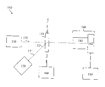
With reference to FIG. 1, a first embodiment of the particle analyzer 100
includes a sample cell
110, a dark-field light source 120, a bright-field light source 130, an
imaging system 140, a
processing system 150, and a pumping system 160. The imaging system 140
typically includes a
magnification system 141 and a detector array 142. The processing system 150
typically
includes a control module and an analysis module (not shown). The bright-field
light source
130, the sample cell 110, the magnification system 141, and the detector array
142 are aligned
along an optical axis 170. The dark-field light source 120 and the sample cell
110 are aligned
along a direction 171 at an angle 172 to the optical axis 170.
Typically, the sample cell 110, which holds the liquid sample, is a flow cell.
The pumping
system 160 passes the liquid sample in a flowing stream into the sample cell
110. Preferably, the
pumping system 160 is a pulse pumping system, as described in U.S. Patent No.
7,307,721,
which passes the liquid sample into the sample cell 110 with a pulse. Once the
liquid sample is
6
CA 2775506 2018-08-16
Doc. No.: 100-8 CA
in the sample cell 110, the pumping system 160 substantially stops the stream
to ensure that the
liquid sample is substantially stationary in the sample cell 110 during image-
frame capture. For
example, the flow rate may be on the order of about 1 tm/s. After the liquid
sample has been
imaged, the pumping system 160, with another pulse, passes the liquid sample
in the stream, now
flowing once again, out of the sample cell 110, while passing a subsequent
liquid sample in the
stream into the sample cell 110.
The sample cell 110 is positioned to allow both the dark-field light source
120 and the bright-
field light source 130 to illuminate the liquid sample, and is substantially
transparent to light
emitted from the dark-field light source 120 and the bright-field light source
130. The same
optical sampling volume, which may be less than or equal to the volume of the
sample cell 110,
is illuminated by the dark-field light source 120 and the bright-field light
source 130. The dark-
field light source 120 and the bright-field light source 130 may be lamps,
light-emitting diodes,
lasers, or any other suitable light sources.
The dark-field light source 120 and the bright-field light source 130 may emit
light in the same
wavelength band or in different wavelength bands. For instance, when some of
the particles in
the liquid sample are fluorescent particles, which emit scattered fluorescent
light in a first
wavelength band after absorbing light in a second wavelength band, the dark-
field light source
120 may be a fluorescent light source that illuminates the liquid sample in
the sample cell 110
with light in the second wavelength band, and the bright-field light source
130 may illuminate
the liquid sample in the sample cell 110 with light in the first wavelength
band. A wavelength
selective filter that passes only light in the first wavelength band to the
detector array 142, while
blocking light in the second wavelength band, may be included in the imaging
system 140, as
described in further detail hereafter.
The dark-field light source 120 illuminates the liquid sample in a dark-field
geometry to yield
scattered light. In other words, the dark-field light source 120 laterally
illuminates the liquid
sample to produce an image from light scattered by the liquid sample, in which
particles appear
bright against a dark background. The dark-field light source 120 illuminates
the liquid sample
along a direction 171 at an angle 172 to the optical axis 170 to ensure that a
suitable scattered
7
CA 2775506 2018-08-16
Doc. No.: 100-8 CA
signal from the liquid sample is received by the imaging system 140, while
minimizing
unwanted scatter from the sample cell 110. The angle 172 may be any angle.
The bright-field light source 130 illuminates the liquid sample in a bright-
field geometry to yield
transmitted light. In other words, the bright-field light source 130 trans-
illuminates the liquid
sample to produce an image from light transmitted by the liquid sample, in
which particles
appear dark against a bright background. The bright-field light source 130
illuminates the liquid
sample along the optical axis 170 to ensure that a suitable transmitted signal
from the liquid
sample is received by the imaging system 140.
The dark-field light source 120 and the bright-field light source 130 are
separately activated,
typically in alternation, so that either the scattered light yielded by the
illumination of the liquid
sample with the dark-field light source 120 or the transmitted light yielded
by the illumination of
the liquid sample with the bright-field light source 130 is received by the
imaging system 140.
Typically, the liquid sample is illuminated once with the dark-field light
source 120 and once
with the bright-field light source 130 to acquire a set of two image frames.
The magnification system 141 of the imaging system 140 collects the scattered
light or the
transmitted light and focuses it onto the detector array 142 of the imaging
system 140.
Typically, the magnification system 141 includes an objective, which may be an
objective lens, a
set of objective lenses of different magnifications, a variable-magnification
lens system, or any
other suitable objective, as well as one or more tube lenses. Preferably, the
magnification system
141 also includes a diaphragm for enhancing diffraction enlargement, as
described in U.S. Patent
No. 7,379,577.
The magnification system 141 of the imaging system 140 has a magnification
factor and a
numerical aperture selected to provide a suitable field of view and a suitable
depth of field. The
field of view of the magnification system 141, which corresponds to the cross-
sectional area of
the optical sampling volume, and the depth of field of the magnification
system 141, which
corresponds to the depth of the optical sampling volume, decrease as the
magnification factor
and the numerical aperture increase. The depth of field is usually small. For
instance, the
magnification system may have a magnification factor of 5, a field of view of
about 2.2 mm2,
and a depth of field of about 100 [tm, or a magnification factor of 10, a
field of view of about 0.5
8
CA 2775506 2018-08-16
Doc. No.: 100-8 CA
mm2, and a depth of field of about 30 gm. Preferably, the liquid sample is
confined to the
maximum depth of field of the magnification system 141. For instance, the
sample cell 110 may
be designed to have a depth that is less than or equal to the maximum depth of
field of the
magnification system 141.
The detector array 142 of the imaging system 140 detects the scattered light
or the transmitted
light to capture a dark-field or bright-field image frame, respectively. The
detector array 142
includes a plurality of detector elements. Typically, the detector array
includes greater than 1
000 000 detector elements of about 4 gm to 6 gm in size. The detector array
142 detects the
intensity of light incident on the plurality or detector elements and thereby
captures a digital
image frame formed of a plurality of pixels. The detector array 142 may be a
charge-coupled
device (CCD) array, a complementary metal-oxide semiconductor (CMOS) array, or
any other
suitable detector array.
Although it is preferred that a single detector array 142 of the imaging
system 140 detects both
the scattered light and the transmitted light, other embodiments may include
two separate
detector arrays 142 for detecting the scattered light and the transmitted
light, respectively. For
instance, in such an embodiment, the dark-field light source 120 and the
bright-field light source
130 may emit light in two different wavelength bands, and two wavelength
selective filters that
each pass only light in one of the wavelength bands to a respective detector
array 142, while
blocking light in the other wavelength band, may be included in the imaging
system 140.
A set of image frames, typically consisting of a dark-field image frame and a
bright-field image
frame, is captured for each liquid sample. In operation, the pumping system
160 passes the
liquid sample in a flowing stream into the sample cell 110 and then
substantially stops the
stream. The dark-field light source 120 illuminates the liquid sample in the
sample cell 110, and
the detector array 142 of the imaging system 140 captures a dark-field image
frame. The bright-
field light source 130 illuminates the liquid sample in the sample cell 110,
and the detector array
142 captures a bright-field image frame. The pumping system 160 then passes
the liquid sample
in the stream out of the sample cell 110, while passing a subsequent liquid
sample in the stream,
now flowing once again, into the sample cell 110. These steps are repeated
until the required
volume of liquid has been analyzed.
9
CA 2775506 2018-08-16
Doc. No.: 100-8 CA
The time and intensity of illumination provided by the dark-field light source
120 and the bright-
field light source 130 during image-frame capture, the flow rate of the liquid
sample during
image-frame capture as regulated by the pumping system 160, and the rate of
image-frame
capture by the detector array 142 of the imaging system 140 are selected to
ensure that "freeze
frame" conditions prevail as the set of image frames is captured, meaning that
particles move by
less than a significant fraction, typically about 5 % to 15 %, of their
dimensions.
The control module of the processing system 150 controls the detector array
142 to determine the
rate of image-frame capture. Preferably, the control module also controls the
dark-field light
source 120 and the bright-field light source 130 to determine the time of
illumination, as well as
the pumping system 160 to determine the flow rate. Thereby, the control module
synchronizes
the dark-field light source 120, the bright-field light source 130, the
pumping system 160, and
the detector array 142 of the imaging system 140 to ensure that the dark-field
image frame and
the bright-field image frame are successively captured, in either order, while
the liquid sample is
substantially stationary in the sample cell 110.
The processing system 150 receives the captured dark-field and bright-field
image frames from
the detector array 142 of the imaging system 140, stores the image frames,
displays the image
frames for viewing, and analyzes the image frames. Typically, the processing
system 150
includes a memory and a suitably programmed processor, such as a central
processing unit
(CPU), a digital signal processor (DSP), a field-programmable gate array
(FPGA), or any other
suitable processor. The control module and the analysis module of the
processing system 150
are typically implemented as software.
The analysis module of the processing system 150 records background
intensities of each pixel
when no sample particles are present in the sample cell 110. These background
intensities are
used to perform background subtraction and to minimize the effects of stuck
particles or other
fixed artifacts in the sample cell 110.
In the dark-field image frame, the particles of the lower size range and the
particles of the
intermediate size range are resolved. Generally, the particles of the upper
size range are not
resolved in the dark-field image frame because of blooming effects. Scattered
particle images
CA 2775506 2018-08-16
Doc. No.: 100-8 CA
appear in the dark-field image frame as bright "stars" against a dark
background. An exemplary
dark-field image frame 243 is shown in FIG. 2.
The analysis module of the processing system 150 first analyzes the dark-field
image frame to
locate the images of the particles of the lower size range and the particles
of the intermediate size
range. The analysis module compares the intensity of each pixel in the digital
image frame to a
predetermined intensity threshold. The predetermined intensity threshold is
selected to provide
the most sensitive detection of pixels located wholly or partially in particle
images, while
minimizing incorrect counting of pixels whose intensity varies because of
optical and/or
electrical noise. If a cluster of adjacent pixels, typically at least 5
adjacent pixels, have
intensities larger than the intensity threshold, the cluster is interpreted as
a particle image, and
the location of the particle image in the dark-field image frame is stored.
The analysis module of the processing system 150 then analyzes the located
images of the
particles of the lower size range and the particles of the intermediate size
range by determining
their sizes and intensities. The size of each particle image is determined by
counting the pixels
within the particle image. The intensity of each particle image is determined
by averaging the
intensities of the pixels within the particle image. The size and intensity of
the particle image are
dependent on the scattering power of that particle. The scattering power of
the particle, in turn,
is dependent on the size of the particle, as well as factors such as the
optical properties of the
particle, and the angles of illumination and detection. On this basis, the
analysis module
determines the relative sizes of the particles of the lower size range and the
particles of the
intermediate size range from the sizes and intensities of their particle
images. However, as the
scattering power of a particle increases rapidly with size, leading to
oversaturation of the detector
elements and blooming effects in the particle image, the relative sizes of the
particles of the
upper size range cannot be determined reliably.
In the bright-field image frame, the particles of the intermediate size range
and the particles of
the upper size range are resolved. Generally, the particles of the lower size
range are not
resolved in the bright-field image frame because of insufficient contrast.
Transmitted particle
images appear in the bright-field image frame as dark shadows against a bright
background. An
exemplary bright-field image frame 344 is shown in FIG. 3.
11
CA 2775506 2018-08-16
Doc. No.: 100-8 CA
The analysis module of the processing system 150 first analyzes the bright-
field image frame to
locate the images of the particles of the intermediate size range and the
particles of the upper size
range. The analysis module compares the intensity of each pixel in the digital
image frame to a
predetermined intensity threshold. The predetermined intensity threshold is
selected to provide
the most sensitive detection of pixels located wholly or partially in particle
images, while
minimizing incorrect counting of pixels whose intensity varies because of
optical and/or
electrical noise. If a cluster of adjacent pixels, typically at least 5
adjacent pixels, have
intensities smaller than the intensity threshold, the cluster is interpreted
as a particle image, and
the location of the particle image in the bright-field image frame is stored.
The analysis module of the processing system 150 then analyzes the located
images of the
particles of the intermediate size range and the particles of the upper size
range by determining
their sizes. The size of each particle image is determined by counting the
number of pixels
within the particle image. The size of the particle image is related to the
size of that particle by
the magnification factor of the magnification system 141 and any additional
diffraction
.. enlargement. Advantageously, the size of the particle image is
substantially independent of
factors such as the optical properties of the particle. On this basis, the
analysis module
determines the absolute sizes of the particles of the intermediate size range
and the particles of
the upper size from the sizes of their particle images. However, as the
interaction of a particle
with the bright-field illumination decreases with size, leading to
insufficient contrast between the
particle image and the background, and to an insufficient number of pixels in
the particle image,
absolute sizes of the particles of the lower size range cannot be determined
reliably. In some
instances, it may be desirable to use contrast enhancement techniques, as
described in U.S.
Patent No. 7,605,919.
The analysis module of the processing system 150 compares the dark-field image
frame and the
bright-field image frame to identify corresponding images of the particles of
the intermediate
size located in both the dark-field image frame and the bright-field image
frame. For each
particle image in the dark-field image frame, the analysis module compares its
stored location
with the stored locations of the particle images in the bright-field image
frame. If the stored
locations of a set of particle images differ by less than a predetermined
displacement threshold,
the set of particle images are interpreted as corresponding images of the same
particle of the
12
CA 2775506 2018-08-16
Doc. No.: 100-8 CA
intermediate size range. For example, the predetermined displacement threshold
may be less
than about 5% of the length of the field of view and less than about 1% of the
width of the field
of view.
In effect, the particles of the intermediate size range, for which
corresponding particle images are
located in the dark-field and the bright-field image frames, serve as internal
calibration
standards. The analysis module of the processing system 150 determines a
calibration curve by
comparing the relative sizes and the absolute sizes of the particles of the
intermediate size range,
which were determined by analyzing the corresponding images of the particles
of the
intermediate size range located in the dark-field image frame and the bright-
field image frame,
respectively. Generally, the calibration curve is generated by fitting the
size data, for example,
by using a polynomial function. Typically, a look-up table is also generated.
The analysis module of the processing system 150 then applies the calibration
curve to the
relative sizes of the particles of the lower size range to determine
calibrated sizes of the particles
of the lower size range. In other words, the analysis module uses the
calibration curve to convert
the relative sizes of the particles of the lower size range, which were
determined by analyzing the
images of the particles of the lower size range located in the dark-field
image frame, to calibrated
sizes.
Finally, the analysis module of the processing system 150 determines the
particle size
distribution of the liquid sample from the calibrated sizes of the particles
of the lower size range,
and the absolute sizes of the particles of the intermediate size range and the
particles of the upper
size range. Typically, the analysis module of the processing system 150 also
displays the
particle size distribution for viewing.
With reference to FIGS. 4A and 4B, a second embodiment of the particle
analyzer 400 is similar
to the first embodiment, but includes a specially adapted sample cell 410, and
a dark-field light
source 420 that is aligned with the sample cell 410 along a direction 471 at
an angle 472 of about
90 to the optical axis 170.
The specially adapted sample cell 410 includes a side window 411 that is
substantially
transparent to light emitted from the dark-field light source 420. The sample
cell 410 also
13
CA 2775506 2018-08-16
Doc. No.: 100-8 CA
includes a front window 412 and a back window 413 that are substantially
transparent to light
emitted from the bright-field light source 130. Preferably, the front window
412 and the back
window 413 are substantially parallel and are separated by a depth that is
less than or equal to the
maximum depth of field of the magnification system 141. For example, the
sample cell 110 may
have a depth of about 100 gm or about 30 gm.
The sample cell 410 is positioned such that the side window 411 receives light
from the dark-
field light source 420 and the front window 412 receives light from the bright-
field light source
130. The dark-field light source 420 illuminates the liquid sample along the
direction 471
substantially orthogonal to the optical axis 170, and as in the first
embodiment, the bright-field
light source 130 illuminates the liquid sample along the optical axis 170.
With particular reference to FIG. 4B, preferably, the dark-field light source
420 is a laser, and the
particle analyzer 400 includes a sheet-forming system 421, which is positioned
between the dark-
field light source 420 and the sample cell 410. The sheet-forming system 421
forms the light
emitted from the dark-field light source 420 into a light sheet substantially
parallel to the front
window 412 and the back window 413, and directed into the side window 411 of
the sample cell
410.
In one embodiment, the sheet-forming system 421 includes a spherical lens 422
and a cylindrical
lens 423. The spherical lens 422 collimates the light emitted from the dark-
field light source
420, and the cylindrical lens 423 focuses the collimated light into a light
sheet directed into the
side window 411 of the sample cell 410. Any other suitable embodiment of a
sheet-forming
system may also be used.
Typically, the focused light sheet, in free space, has a Gaussian intensity
distribution, and the
intensity of the light sheet varies along its direction of propagation and
along its narrow
direction. These intensity variations can reduce the resolution with which
particles of different
sizes can be distinguished.
Advantageously, the sample cell 410 reduces such intensity variations in the
light sheet by
effectively serving as an optical waveguide. The front window 412 and the back
window 413 of
the sample cell 410 serve as highly reflective, substantially parallel walls,
separated by a narrow
14
CA 2775506 2018-08-16
Doc. No.: 100-8 CA
depth. The high degree of reflection results from the low angle of incidence
of the light sheet on
the front window 412 and the back window 413. The reflection is further
enhanced by ensuring
that the polarization axis of the light sheet lies in a plane substantially
parallel to the front
window 412 and the back window 413. When propagating through the sample cell
410, the light
sheet is partially confined and diverges to a lesser degree than it would in
free space. The partial
confinement also reduces the angular accuracy with which the light sheet must
be directed
between the front window 412 and the back window 413. Preferably, the front
window 412 and
the back window 413 are formed of a low-index glass, such as silica.
With reference to FIG. 5, a third embodiment of the particle analyzer 500 is
useful in instances
where some of the particles in the liquid sample are fluorescent particles,
having either natural
fluorophores or fluorophore tags, which emit fluorescent light in a first
wavelength band afler
absorbing light in a second wavelength band.
The third embodiment of the particle analyzer 500 is similar to the first
embodiment, but
includes an additional fluorescence light source 580 that is aligned with the
sample cell 110
along a direction 573 at an angle 574 to the optical axis 170, and an imaging
system 540
comprising a wavelength selective filter 543. The angle 574 may be any angle.
The fluorescence light source 580 illuminates the liquid sample in the sample
cell 110 with light
in the second wavelength band to yield fluorescent light in the first
wavelength band, as well as
scattered light in the second wavelength band. The dark-field light source 120
and the bright-
field light source 130 illuminate the liquid sample in the sample cell 110
with light in the first
wavelength band to yield scattered light or transmitted light, respectively,
in the first wavelength
band. Typically, the liquid sample is illuminated once with the dark-field
light source 120, once
with the bright-field light source 130, and once with the fluorescence light
source 580 to capture
a set of three image frames, consisting of a dark-field image frame, a bright-
field image frame,
and a fluorescence image frame. The dark-field image frame, the bright-field
image frame, and
the fluorescence image frame are successively captured, in any order, while
the liquid sample is
substantially stationary in the sample cell 110, that is, under "freeze frame"
conditions, as
described heretofore.
CA 2775506 2018-08-16
Doc. No.: 100-8 CA
The wavelength selective filter 543 of the imaging system 540 passes the
scattered light, the
transmitted light, and the fluorescent light in the first wavelength band to
the detector array 142
of the imaging system 540, while blocking the scattered light in the second
wavelength band.
The wavelength selective filter 543 is preferably positioned within the
magnification system 141
of the imaging system 540, but may also be positioned between the
magnification system 141
and the detector array 142 or between the sample cell 110 and the
magnification system 141.
Accordingly, the magnification system 141 of the imaging system 540 collects
and focuses the
scattered light, the transmitted light, or the fluorescent light in the first
wavelength band onto the
detector array 142 of the imaging system 540. The detector array 142 detects
the scattered light,
the transmitted light, or the fluorescent light in the first wavelength band
to capture a dark-field,
bright-field, or fluorescence image frame, respectively.
The processing system 150 receives the captured dark-field, bright-field, and
fluorescence image
frames from the detector array 142, stores the image frames, displays the
image frames for
viewing, and analyzes the image frames. The dark-field and bright-field image
frames are
analyzed as described heretofore.
The analysis module of the processing system 150 first analyzes the
fluorescence image frame to
locate images of the fluorescent particles. The analysis module compares the
intensity of each
pixel in the digital image frame to a predetermined intensity threshold. The
predetermined
intensity threshold is selected to provide the most sensitive detection of
pixels located wholly or
partially in particle images, while minimizing incorrect counting of pixels
whose intensity varies
because of optical and/or electrical noise. If a cluster of adjacent pixels,
typically at least 5
adjacent pixels, have intensities larger than the intensity threshold, the
cluster is interpreted as a
particle image, and the location of the particle image in the fluorescence
image frame is stored.
The analysis module of the processing system 150 then compares the dark-field,
bright-field, and
fluorescence image frames to identify corresponding images of the fluorescent
particles in the
fluorescence image frame and in either or both of the dark-field and bright-
field image frames.
For each particle image in the fluorescence image frame, the analysis module
compares its stored
location with the stored locations of the particle images in the dark-field
and bright-field image
frames. If the stored locations of a set of particle images differ by less
than a predetermined
16
CA 2775506 2018-08-16
Doc. No.: 100-8 CA
displacement threshold, the set of particle images are interpreted as
corresponding images of the
same fluorescent particle. For example, the predetermined displacement
threshold may be less
than about 5% of the length of the field of view and less than about 1% of the
width of the field
of view.
Thereby, the analysis module of the processing system 150 may identify images
of the
fluorescent particles of the lower size range and the fluorescent particles of
the intermediate size
range in the dark-field image frame, and may identify images of the
fluorescent particles of the
intermediate size range and the fluorescent particles of the upper size range
in the bright-field
image frame. Furthermore, the analysis module may determine a size
distribution of only the
.. fluorescent particles in the liquid sample from the calibrated sizes of the
fluorescent particles of
the lower size range, and the absolute sizes of the fluorescent particles of
the intermediate size
range and the fluorescent particles of the upper size range.
Of course, numerous other embodiments may be envisaged without departing from
the spirit and
scope of the invention.
17
CA 2775506 2018-08-16