Note: Descriptions are shown in the official language in which they were submitted.
CA 02776045 2012-03-29
WO 2011/046543
PCT/US2009/060450
- -
ROTOR YOKE AND METHOD OF MAKING THE SAME
Technical Field
The present application relates to rotorcraft and, in particular, to yokes for
coupling helicopter blades to a mast.
Description of the Prior Art
Each blade of the main rotor assembly of a rotorcraft must be connected to a
main support mast, usually by means of a rotor yoke, in a manner allowing
several
degrees of freedom. Such an interconnection is subjected to high and repeated
stresses of both torsional and centrifugal natures, and is therefore an
extremely
important component of the aircraft. Each blade must be able to rotate about
its
longitudinal axis to provide pitch control. Each blade must be able to flap in
a direction
perpendicular to the rotor plane to accommodate vertical loads. In some
instances,
each blade must be able to pivot within the rotor plane to provide for lead-
lag control.
The manner in which the blades are secured to the main support mast enables a
rotorcraft to be controlled and maneuvered in flight.
Various types of rotor yokes have been utilized to interconnect the rotorcraft
blades and the support mast. Metal rotor yokes have suffered from the
disadvantages
of weight, cost, high maintenance requirements, and low useful life. There
have been
several attempts to eliminate one or more of the articulations in such
couplings in order
to simplify construction and reduce costs. Some rotor yokes are pivotally
secured to the
support mast, and are characterized by a flat plate construction resilient
enough to act
as a virtual hinge and thereby accommodate flapping of the blades.
More recently, glass fibers and other composite materials have been employed
in
the fabrication of rotorcraft rotor system components. In comparison to a
machined
metal forging, glass fibers and other composite materials have more favorable
fatigue
CA 02776045 2014-06-12
- 2 -
characteristics resulting in longer useful life. In addition, the use of such
materials
simplifies construction and reduces costs. Referring to Figures 1 and 2,
composite
rotor yokes, such as a rotor yoke 101 are conventionally cured in a rigid,
closed
mold, such as mold 103, to form the overall shape of the rotor yoke. One of
the
problems encountered concerning such rotorcraft rotor yokes has been
distortion or
"marcelling" of the fibers in the rotor yoke during the curing process.
Because the
uncured rotor yoke is forced to conform to the cavity, such as cavity 105
formed by
the closed mold, mechanical stresses can be induced in the uncured rotor yoke.
The
fibers are substantially unconstrained during certain portions of the curing
cycle
when the resin matrix in which the fibers are disposed is in a semi-liquid or
liquid
state. The induced stress in the uncured rotor yoke is relieved via movement
or
distortion of the fibers within the resin matrix. The fibers can be captured
in their
distorted or marcelled state when the resin crosslinks in thermosetting
composite
materials or when the resin is cooled in thermoplastic composite materials.
There are many designs of rotorcraft yokes well known in the art; however,
considerable shortcomings remain.
Summary
In one aspect, there is provided a method of making a rotor yoke, comprising:
preparing a molded rotor yoke in a closed cavity tool, comprising: applying
layers of
uncured low-flow composite material and at least one layer of uncured high-
flow
adhesive in a configuration to produce an uncured molded rotor yoke, the high-
flow
adhesive having a lower viscosity than that of the low-flow composite
material;
substantially enclosing the uncured molded rotor yoke in the closed cavity
tool,
wherein the closed cavity tool comprises a first tool and a second tool;
forcing the
first tool and the second tool together, so as to compress the uncured molded
rotor
yoke; and curing the uncured molded rotor yoke.
CA 02776045 2014-06-12
- 2a -
In another aspect, there is provided a rotor yoke, comprising: layers of low-
flow composite material; and at least one layer of high-flow adhesive applied
adjacent to the layers of low-flow composite material, the high-flow adhesive
having
a lower viscosity than that of the low-flow composite material; wherein the
layers of
low-flow composite material and high-flow adhesive having been compressed and
cured in a closed cavity tool.
In a particular embodiment, the low-flow composite material comprises fibers
impregnated in uncured epoxy or adhesive.
Brief Description of the Drawings
The novel features believed characteristic of the present application are set
forth in the appended claims. However, the system itself, as well as a
preferred
mode of use, and further objectives and advantages thereof, will best be
understood
by reference to the following detailed description when read in conjunction
with the
accompanying drawings, in which the leftmost significant digit(s) in the
reference
numerals denote(s) the first figure in which the respective reference numerals
appear, wherein:
Figures 1 and 2 are stylized, cross-sectional views illustrating a
conventional
method for manufacturing a composite rotor yoke for a rotorcraft according to
prior
art;
CA 02776045 2014-06-12
- 3 -
Figures 3-5 are stylized, cross-sectional views depicting the method of
manufacturing a composite molded rotor yoke according to the preferred
embodiment of the present application;
Figures 6-8 are stylized, cross-sectional views depicting the method of
manufacturing a composite molded rotor yoke according to an alternative
embodiment of the present application;
Figure 9 is a stylized, cross-sectional view of a molded rotor yoke according
to
an alternative embodiment of the present application;
Figure 10 is a top, plan view of a composite rotor yoke according to the
preferred embodiment of the present application; and
Figure 11 is a top, plan view of a rotor hub incorporating a pair of composite
rotor yokes of Figure 10 according to the preferred embodiment of the present
application.
While the system of the present application is susceptible to various
modifications and alternative forms, specific embodiments thereof have been
shown
by way of example in the drawings and are herein described in detail. It
should be
understood, however, that the description herein of specific embodiments is
not
intended to limit the present application to the particular forms disclosed,
but on the
contrary, the intention is to cover all modifications, equivalents, and
alternatives
falling within the scope of the present application as defined by the appended
claims.
Description of the Preferred Embodiment
The system of the present application represents a composite rotor yoke for a
rotorcraft produced using a closed cavity curing tool. Preferably, the
composite rotor
yoke is laid-up using an automated fiber placement process, but may also be
laid-up
by hand. After curing, the cured composite rotor yoke may be machined to add
any
desired features.
CA 02776045 2012-03-29
WO 2011/046543
PCT/US2009/060450
- 4 -
Illustrative embodiments of the present application are described below. In
the
interest of clarity, not all features of an actual implementation are
described in this
specification. It will of course be appreciated that in the development of any
such actual
embodiment, numerous implementation-specific decisions must be made to achieve
the
developer's specific goals, such as compliance with system-related and
business-
related constraints, which will vary from one implementation to another.
Moreover, it will
be appreciated that such a development effort might be complex and time-
consuming
but would nevertheless be a routine undertaking for those of ordinary skill in
the art
having the benefit of this disclosure.
As used herein, reference may be made to the spatial relationships between
various components and to the spatial orientation of various aspects of
components as
the devices are depicted in the attached drawings. However, as will be
recognized by
those skilled in the art after a complete reading of the present application,
the devices,
members, apparatuses, etc. described herein may be positioned in any desired
orientation. Thus, the use of terms such as "above," "below," "upper,"
"lower," or other
like terms to describe a spatial relationship between various components or to
describe
the spatial orientation of aspects of such components should be understood to
describe
a relative relationship between the components or a spatial orientation of
aspects of
such components, respectively, as the device described herein may be oriented
in any
desired direction.
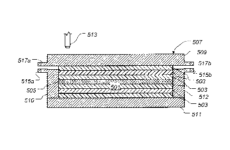
Referring to Figures 3-5 in the drawings, the preferred embodiment of a
composite molded rotor yoke 501 of a rotor yoke 901 (shown in Figure 10) is
fabricated
by applying a plurality of layers of an uncured low-flow composite material
503 and a
layer of a high-flow adhesive 505 into a closed cavity tool 507. Note that the
geometric
configuration of tool 507 is merely exemplary of the widely diverse geometric
configurations of closed cavity tools contemplated by the present application.
It should
be appreciated that tools 509, 510, 511, and 512 may be split into multiple
tools, or
combined to form a fewer number of tool parts. For example, side tools 510 and
512
CA 02776045 2012-03-29
WO 2011/046543
PCT/US2009/060450
- 5 -
may be integrated into a second tool 511 so as to form one integral tool part.
Closed
cavity tool 507 preferably has a rigid first tool 509, a rigid second tool
511, and rigid side
tools 510 and 512. However, closed cavity tool 507 may also have a semi-rigid
first tool
509, a semi-rigid second tool 511, semi-rigid side tools 510 and 512, or any
combination
of semi-rigid and rigid tools 509, 511, 510, and 512. Closed cavity tool 507
provides
tolerance and contour control by conforming the primary surfaces of molded
rotor yoke
501 to the inside surfaces of closed cavity tool 507. Closed cavity tool 507
may also be
referred to as a "two-sided" tool or other language describing that tool 507
substantially
encloses molded rotor yoke 501.
Uncured, composite molded rotor yoke 501 is formed when the desired number
of layers, also referred to as "plies", of low-flow composite material 503 and
high-flow
adhesive 505 have been applied into tool 507, in the desired geometry. Layers
of low-
flow composite material may be laid by hand, or by fiber placement machine
513. High-
flow adhesive 505 may also be laid by hand, or by a machine similar to fiber
placement
machine 513. Closed cavity tool 507 is capable of compressing molded rotor
yoke 501
into a desired thickness and geometry. Closed cavity tool 507 may include
stops 515a
and 515b so that first tool 509 and second tool 511 of tool 507 will stop the
compression
of molded rotor yoke 501 at the desired thickness of molded rotor yoke 501.
Closed
cavity tool 507 may also include fastener holes 517a and 517b so that closed
cavity tool
507 could be fastened closed with fasteners 521a and 521b at any time during
or after
the curing process.
Uncured low-flow composite material 503 preferably includes glass fibers
disposed in an uncured epoxy, in the form of a prepreg, although the present
application
contemplates other materials for molded rotor yoke 501. An example of low-flow
composite material 503 is HexPly 8552 made by Hexcel Composites. For this
application, the term "prepreg" is typically sheets of fibers impregnated in
uncured
epoxy or adhesive. Uncured low-flow composite material 503 can then be cut to
size
and laid into tool 507, either by hand or with fiber placement machine 513.
Low-flow
CA 02776045 2012-03-29
WO 2011/046543
PCT/US2009/060450
- 6 -
composite material 503, if used in the absence of high-flow adhesive 505,
could be any
composite material that has such a high viscosity so as to possibly produce
marcels
when subjected to a curing process inside a closed cavity tool 507. "Marcels"
are
wrinkles in the fiber structure of a composite that severely compromise the
structural
integrity of a composite part. Marcels are often created when low-flow
composite
material 503, if used in the absence of high-flow adhesive 505, is forced to
conform to
the inside surface of closed cavity tool 507, causing the highly viscous epoxy
to flow
and distort fibers. Complete curing of the distorted fibers, or marcels,
causes the fibers
to be permanently fixed in the marcelled state.
The system of the present application seeks to at least prevent the formation
of
"marcels" by applying layers of uncured low-flow composite material 503, as
well as a
layer of uncured high-flow adhesive 505, in a configuration to produce molded
rotor
yoke 501. In an alternative embodiment, a plurality of layers of high-flow
adhesive 505
may also be used in conjunction with a plurality of layers of low-flow
composite material
503, to form molded rotor yoke 801 (see Figure 9). The use of uncured high-
flow
adhesive 505 in conjunction with low-flow composite material 503 provides a
material
with low viscous properties that easily bleeds out of tool 507 during curing,
thereby
preventing low-flow composite material 503 from forming marcels. An example of
high-
flow adhesive 505 is AF163 made by 3M. High-flow adhesive 505 is preferably,
in its
uncured state, a film, but may also be a paste. High-flow adhesive 505 may
also be
impregnated with fibers or scrim in order to tailor strength and final
thickness control.
Figure 4 depicts molded rotor yoke 501 during the curing process. Closed
cavity
tool 507 has been compressed in order to rid the part of any voids, or air
bubbles, and
to conform molded rotor yoke 501 to the contours of two sided tool 507.
Mechanical
stops 515a and 515b of second tool 511 are shown in contact with first tool
509.
Contact between stops 515a and 515b, and first tool 509, signify the desired
final
thickness of molded rotor yoke 501 has been reached. Bleed outs 519a and 519b
of
high-flow adhesive 505 are caused from compression of tool 507. During curing,
high-
CA 02776045 2012-03-29
WO 2011/046543
PCT/US2009/060450
- 7 -
flow adhesive 505 may either partially or completely bleed out from molded
rotor yokes
501 and 801, depending on parameters controlling compression of tool 507.
Because
high-flow adhesive 505 has a lower viscosity than that of low-flow composite
material
503, high-flow adhesive 505 bleeds out of tool 507 instead of low-flow
composite
material 503. In some embodiments, the viscosity difference between high-flow
adhesive 505 and low-flow composite material 503 may not be large, which could
result
in bleed outs 519a and 519b being a combination of high-flow adhesive 505 and
low-
flow composite material 503. Curing the uncured molded rotor yoke 501
is
accomplished by applying at least one of heat, pressure, and time. In
alternative
embodiment, the curing of rotor yoke molded rotor yoke 501 may involve
subjecting
molded rotor yoke 501 to a vacuum. Another alternative embodiment involves
releasably coupling first tool 509 and second tool 511, via fasteners 521a and
521b,
while allowed uncured molded rotor yoke 501 to soak at an ambient temperature
environment. The specific amount of variables such as heat, pressure, or time,
depend
up on at least the specific curing requirements of the low-flow composite
material 503
and high-flow adhesive 505 used to form molded rotor yoke 501. The location of
bleed
outs 519a and 519b may be located anywhere on tool 507 that allows high-flow
adhesive 505 to escape or bleed out during the curing process; however, it is
preferred
that bleed outs 519a and 519b be located on the upper side of tool 507 so as
to prevent
the introduction of air bubbles into molded rotor yoke 501.
Figure 5 depicts molded rotor yoke 501 after the curing cycle has been
completed. Bleed outs 519a and 519b have been removed from molded rotor yoke
501
by force and then lightly sanded to remove any sharp edges. Layer of high-flow
adhesive 505 has decreased in thickness due to partially bleeding out during
the curing
process.
Referring to Figures 6-8 in the drawings, an alternative embodiment of a
composite molded rotor yoke 601 of rotor yoke 901 (shown in Figure 10) is
fabricated by
applying a plurality of layers of uncured low-flow composite material 503 and
a layer of
CA 02776045 2012-03-29
WO 2011/046543
PCT/US2009/060450
- 8 -
high-flow adhesive 505 into a closed cavity tool 607. Note that the geometric
configuration of tool 607 is merely exemplary of the widely diverse geometric
configurations of closed cavity tools contemplated by the present application.
Closed
cavity tool 607 preferably has a rigid first tool 609 and a rigid second tool
611.
However, closed cavity tool 607 may also have a semi-rigid first tool 609, a
semi-rigid
second tool 611, or any combination of semi-rigid and rigid tools 609 and 611.
It should
be appreciated that tools 609 and 611 may be split into multiple tools. For
example, first
tool 609 may be formed as two separate tools. Closed cavity tool 607 provides
tolerance and contour control by conforming the primary surfaces of molded
rotor yoke
601 to the inside surfaces of closed cavity tool 607. Closed cavity tool 607
may also be
referred to as a "two-sided" tool or other language describing that tool 607
substantially
encloses molded rotor yoke 601.
Uncured, composite molded rotor yoke 601 is formed when the desired number
of layers, also referred to as "plies", of low-flow composite material 503 and
high-flow
adhesive 505 have been applied into tool 607, in the desired geometry. Layers
of low-
flow composite material may be laid by hand, or by fiber placement machine
513. High-
flow adhesive 505 may also be laid by hand, or by a machine similar to fiber
placement
machine 513. Closed cavity tool 607 is capable of compressing molded rotor
yoke 601
into a desired thickness and geometry. Closed cavity tool 607 may include
stops 615a
and 615b so that first tool 609 and second tool 611 of tool 607 will stop the
compression
of molded rotor yoke 601 at the desired thickness of molded rotor yoke 601. It
should
be appreciated that stops 615a and 615b may be alternatively integrated into
second
tool 611, or stops 615a and 615b may be separate parts while remaining
configured to
stop the compression of first tool 609 and second tool 611 at the appropriate
desired
thickness of molded rotor yoke 601.
Uncured low-flow composite material 503 preferably includes glass fibers
disposed in an uncured epoxy, in the form of a prepreg, although the present
application
contemplates other materials for molded rotor yoke 601. An example of low-flow
CA 02776045 2012-03-29
WO 2011/046543
PCT/US2009/060450
- 9 -
composite material 503 is HexPly 8552 made by Hexcel Composites. For this
application, the term "prepreg" is typically sheets of fibers impregnated in
uncured
epoxy or adhesive. Uncured low-flow composite material 503 can then be cut to
size
and laid into tool 607, either by hand or with fiber placement machine 513.
Low-flow
composite material 503, if used in the absence of high-flow adhesive 505,
could be any
composite material that has such a high viscosity so as to possibly produce
marcels
when subjected to a curing process inside a closed cavity tool 607. "Marcels"
are
wrinkles in the fiber structure of a composite that severely compromise the
structural
integrity of a composite part. Marcels are often created when low-flow
composite
material 503, if used in the absence of high-flow adhesive 505, is forced to
conform to
inside surfaces of closed cavity tool 607, causing the highly viscous epoxy to
flow and
distort fibers. Complete curing of the distorted fibers, or marcels, causes
the fibers to
be permanently fixed in the marcelled state.
Closed cavity tool 607 preferably does not have side tools or bleed out
portions;
instead, tool 607 has space around the periphery of molded rotor yoke 601 for
an
absorbent material 606a and 606b. Absorbent material 606a and 606b functions
at
least to absorb high-flow adhesive 505 as it bleeds outs of molded rotor yoke
601 during
the curing process, as further explained below. Additionally a vacuum bag 604
is
configured in order for a vacuum pump 602 to draw a vacuum on molded rotor
yoke 601
during the curing process. The drawing of a vacuum on molded rotor yoke 601
during
the curing process acts to help remove air bubbles from molded rotor yoke 601.
Though vacuum bag 604 is shown as encapsulating only molded rotor yoke 601, it
should be appreciated that in some embodiments vacuum bag 604 may also
surround
either first tool 609, second tool 611, or both first tool 609 and second tool
611. It
should be appreciated that other materials, such as a breather material, may
be used in
conjunction with vacuum bag 604 in order to draw a vacuum on molded rotor yoke
601.
The system of the present application seeks to at least prevent the formation
of
"marcels" by applying layers of uncured low-flow composite material 503, as
well as a
CA 02776045 2012-03-29
WO 2011/046543
PCT/US2009/060450
- 10 -
layer of uncured high-flow adhesive 505, in a configuration to produce molded
rotor
yoke 601. In an alternative embodiment, a plurality of layers of high-flow
adhesive 505
may also be used in conjunction with a plurality of layers of low-flow
composite material
503, to form molded rotor yoke 801 (see Figure 9). The use of uncured high-
flow
adhesive 505 in conjunction with low-flow composite material 503 provides a
material
with low viscous properties that easily bleeds out of molded rotor yoke 601
during
curing, thereby preventing the formation of marcels. An example of high-flow
adhesive
505 is AF163 made by 3M. High-flow adhesive 505 is preferably, in its uncured
state, a
film, but may also be a paste. High-flow adhesive 505 may also be impregnated
with
fibers or scrim in order to tailor strength and final thickness control.
Figure 7 depicts molded rotor yoke 601 during the curing process. Closed
cavity
tool 607 has been compressed in order to rid the part of any voids, or air
bubbles, and
to conform molded rotor yoke 601 to the primary contours of two sided tool
607.
Mechanical stops 615a and 615b of first tool 609 are shown in contact with
second tool
611. Contact between stops 615a and 615b, and second tool 611, signify the
desired
final thickness of molded rotor yoke 601 has been reached. During this
process, high-
flow adhesive 505 bleeds into absorbent material 606a and 606b due to
compression of
tool 607 and the drawing of a vacuum through vacuum pump 602. During curing,
high-
flow adhesive 505 may either partially or completely bleed out from molded
rotor yokes
601 and 801, depending on the parameters controlling compression of tool 607.
Because high-flow adhesive 505 has a lower viscosity than that of low-flow
composite
material 503, high-flow adhesive 505 bleeds out of tool 607 instead of low-
flow
composite material 503. In some embodiments, the viscosity difference between
high-
flow adhesive 505 and low-flow composite material 503 may not be large, which
could
result in a small amount of resin from low-flow composite material 503 with
the high-flow
adhesive 505 bleeding into absorbent material 606a and 606b. Curing the
uncured
molded rotor yoke 601 is accomplished by applying at least one of heat,
pressure, and
time. An alternative embodiment involves releasably coupling first tool 609
and second
tool 611, via fasteners while allowed uncured molded rotor yoke 601 to soak at
an
CA 02776045 2012-03-29
WO 2011/046543
PCT/US2009/060450
- -
ambient temperature environment. The specific amount of variables such as
heat,
pressure, or time, depend up on at least the specific curing requirements of
the low-flow
composite material 503 and high-flow adhesive 505 used to form molded rotor
yoke
601.
Figure 8 depicts molded rotor yoke 601 after the curing cycle has been
completed. The layer of high-flow adhesive 505 has decreased in thickness
because of
adhesive 505 partially bleeding out during the curing process.
Figure 9 depicts an alternative embodiment of molded rotor yoke 801 that was
formed by either the process used to form molded rotor yoke 501 or molded
rotor yoke
601, except that a plurality of layers of high-flow adhesive 505 were used.
Multiple
layers of high-flow adhesive 505 allows for a greater amount of high-flow
adhesive 505
available for bleed out. Using a plurality of layers of high-flow adhesive 505
can be
advantageous for many reasons, such as for tailoring the material properties
of molded
rotor yoke 801, as well as for allowing for greater contour variation in tools
507 and 607.
Figure 10 depicts a preferred embodiment of a rotorcraft rotor yoke 901. Rotor
yoke 901 is preferably made from molded rotor yoke 501, but may also be made
from
molded rotor yoke 601 or 801. Rotor yoke 901 exemplifies features that may be
machined into molded rotor yokes 501, 601, and 801 using a machining tool such
as a
five-axis machine tool. Such features include: inner openings 905a, 905b, and
905c,
outer periphery 903, rotor blade attachment holes 907a and 907b, and mast
attachment
holes 909a-909h, to name a few. Rotor yoke 901 is formed when all machining
operations are complete. It should be noted that, in one embodiment, molded
rotor
yoke 501, 601, and 801 are oversized, i.e., is larger in physical dimensions
than rotor
yoke 901 to provide material for removal during a machining process to form
machine
outer periphery 903 (shown in Figure 10). Moreover, dimensions of openings
905a,
905b, and 905c maybe incorporated into molded rotor yokes 501, 601, or 801 and
then
increased in size by a subsequent machining operation.
CA 02776045 2014-06-12
- 12 -
Figure 11 depicts the preferred embodiment of a rotor hub 1001 comprising a
pair of rotor yokes 901, a coupling 1003 that mechanically couples rotor yokes
901 to
a mast 1005, and fittings 1007a-1007d that mechanically couple rotor yokes 901
to
rotor blades 1009a-1009d, respectively. The configuration of rotor hub 1001
depicted in Figure 11 is merely exemplary of the widely various embodiments of
rotor
hub 1001 contemplated by the present application.
It should be noted, that the methods disclosed in the present application can
be applied to form composite structures other than rotor yoke 901 or molded
rotor
yokes 501, 601, and 801. Any composite structure that uses low-flow composite
material 503 that is susceptible to marcelling, or other fiber distortion,
during
compression in a closed cavity tool such as closed cavity tools 507 or 607,
would
benefit from the methods disclosed in the present application. Examples of
composite structures that would fall into this category include, but not
limited to,
composite structures used in aircraft, wind turbines, automobiles, marine
vehicles,
etc.
The system of the present application provides significant advantages,
including: (1) ability to use two-side tooling while providing a composite
rotor yoke
without marcelling of the reinforcing fibers thereof; (2) enabling the use of
toughened, low-flow resins in composite rotor yokes in a closed cavity tool;
and (3)
providing a composite rotor yoke that requires less composite fabrication
time, cost,
and effort with less part-to-part variation than conventional rotor yokes.
The particular embodiments of the system of the present application disclosed
may be modified and practiced in different but equivalent manners apparent to
those
skilled in the art having the benefit of the teachings herein. Furthermore, no
limitations are intended to the details of construction or design herein
shown, other
than as described in the claims below. It is therefore evident that the
particular
embodiments disclosed above may be altered or modified and all such variations
are
considered within the scope of the present application. Accordingly, the
protection
sought herein is as set forth in the claims below. It is apparent that a
system with
significant advantages has been described and illustrated. Although the system
of
CA 02776045 2014-06-12
- 13 -
the present application is shown in a limited number of forms, it is not
limited to just
these forms, but is amenable to various changes and modifications.