Note: Descriptions are shown in the official language in which they were submitted.
CA 02777640 2017-02-01
1
Device for climate control of greenhouses
In covered horticulture there is an increasing need to control all parameters
which
influence the growth and the quality of the crops. At the same time, there is
an
imperative necessity to do this with the lowest possible energy consumption,
CO2
production and application of crop-protection products. The moisture
management in
the greenhouse plays an important part here, on the one hand because the
moisture
deficit (difference in absolute humidity and fully saturated humidity in grams
of
moisture per m3 of dry air) determines the absorption of nutrients and the
health of the
plant, on the other because evaporation (or condensation) consumes a
relatively large
amount of energy.
In order to enable control of the temperature in the greenhouse use is also
made, besides
heating means in the heating season, of a device for controlling the climate
in a
greenhouse, comprising a first heat exchanger with a first series of channels
and a
second series of channels, wherein the channels are adapted to mutually
transfer thermal
energy from fluids present in the channels, greenhouse supply means leading
from the
greenhouse to the first channels, outside supply means leading from outside to
the
second channels, greenhouse discharge means leading from the device to the
greenhouse and discharge means leading from the device to the outside, wherein
the
greenhouse discharge means connect to the first series of channels and that
the outside
discharge means connect to the second series of channels, wherein the device
is adapted
to take up a cooling position, in which the temperature of the greenhouse is
reduced, or
a heating position in which the temperature of the greenhouse is increased or
CA 02777640 2017-02-01
2
maintained, and that the device is provided with a second heat exchanger, at
least active
in the heating position, with a third and a fourth series of channels, .
In this known device the heat of the air leaving the greenhouse is transferred
to the air
flowing into the greenhouse. This is of course also the case in the reverse
situation, in
which the temperature in the greenhouse is lower than the temperature outside
the
greenhouse. Air is here however carried outside from the greenhouse, whereby
CO2
from the greenhouse is lost. Fresh air is also supplied to the greenhouse from
outside,
which results in the danger of contamination with pathogens from outside.
As elucidated above, it is important that the air present in the greenhouse
remains in the
greenhouse in order to retain for the crop plant the carbon dioxide present in
and added
to the greenhouse. It is also important that the least possible air is carried
into the
greenhouse from outside in order to keep the danger of contamination and
infection as
small as possible.
For this purpose the present invention provides a device of the above stated
type,
wherein in the heating position the third series of channels of the second
heat exchanger
is connected between the greenhouse supply means and the first channels of the
first
heat exchanger, and the fourth series of channels of the second heat exchanger
is
connected between the first channels of the first heat exchanger and the
greenhouse
discharge means.
The device according to the invention is designed to maintain, within
determined limits
of the temperature, a desired temperature and moisture deficit or dryness,
wherein the
energy consumption is minimal and the greenhouse can remain closed, whereby no
loss
CA 02777640 2017-02-01
3
of CO2 occurs and diseases and vermin do not enter. There is a complete
separation
between the greenhouse air and the outside air so that the added CO2 is not
lost. The
quantity and the quality of the product are increased by the constant spring
climate,
while the time at which production takes place can be moved as desired.
Outside air is used during heating operation to cool the greenhouse air, after
adiabatic
cooling thereof, to well below the condensation point via two air-air heat
exchangers,
after which the sensible and condensation heat is reused again to heat the
greenhouse air
to almost the original temperature, but with a much lower humidity. During
cooling
operation this adiabatically cooled outside air is used to cool and to
dehumidify or dry
the greenhouse air via the air-air heat exchangers, after which the greenhouse
air is
humidified to oversaturation and further cools adiabatically after mixing with
air in the
greenhouse, wherein the moisture deficit is held constant.
The device according to the invention is preferably dimensioned as a module
with a
maximum airflow rate of ¨250 m3h1 in the heating position and ¨400 m311-1 in
the
cooling position. The heat loss in the heating position is in the order of
several percent
relative to the heat loss when the windows are opened. The cooling capacity
increases
with increasing temperature difference between greenhouse and dew point of the
outside air, up to 15 kW at T = 25K. For most crops the greenhouse can remain
closed
at all times when one module is applied per 40 m2.
The modules, each with their own control, can be applied distributed through
the
greenhouse or can be collected and coupled on one side of the greenhouse,
after which
the air distribution takes place via for instance air feeds, depending on the
infrastructure
CA 02777640 2017-02-01
4
in the greenhouse. The temperature and humidity can be controlled in accurate
manner
in that the setting points of the modules incorporated in a network can be
adjusted
individually. The vertical gradients can also be reduced by vertical forcing
of the
airflows of the modules using a hose or channel.
According to a further preferred embodiment, in the heating position a third
series of
channels of a second heat exchanger is connected between the greenhouse supply
means
and the first channels of the first heat exchanger, and a fourth series of
channels of the
second heat exchanger is connected between the first channels of the first
heat
exchanger and the greenhouse discharge means. This is a structurally
attractive
embodiment which limits the number and the length of the channels.
The thermodynamic effects of the device are optimized when in the cooling
position the
third series and fourth series of channels of the second heat exchanger are
connected in
parallel to respectively the first series and the second series of channels of
the first heat
exchanger.
According to an alternative embodiment, fluid only passes through the fourth
series of
channels of the second heat exchanger in the cooling position, and the third
series of
channels of the second heat exchanger is bypassed. Although this gives a sub-
optimal
result, it does greatly simplify the channel configuration.
The configuration can be simplified still further when a three-way valve is
received in
the connection between the first series of channels of the first heat
exchanger and the
fourth series of channels of the second heat exchanger, or in the connection
between the
CA 02777640 2017-02-01
fourth series of channels of the second heat exchanger and the greenhouse
discharge
means. The three-way valve is intended to produce a smooth transition between
the
heating position and the cooling position. This provision prevents oscillation
of the
control.
5
The heat exchanger is preferably formed by a recuperator which is adapted to
periodically, repeatedly and simultaneously interchange the connections
between the
supply means and the first and second series of channels and the connections
between
the discharge means and the first and second series of channels. In addition
to the usual
sensible heat, the latent (condensation) heat is hereby also transferred so
that the overall
heat transfer is more than doubled. This so-called enthalpy recuperator
provides for a
higher dehumidifying and cooling capacity. It is otherwise also possible to
apply a
membrane-enthalpy-recuperator.
The construction of the device is further simplified when the heat exchangers
are each
placed in a rectangular inner casing, openings which can be closed by valves
are
arranged in the inner casing and the inner casing is placed in an outer
casing, the walls
of which, on sides where the openings are made in the inner casing, extend
further
outward than the walls of the inner casing. It hereby becomes structurally
further
advantageous for the openings to be arranged in mutually opposite surfaces of
the inner
casing.
Since the parallel use of the recuperators in the cooling position and the use
of the
heating position with the same channels and plates requires a large number of
plates, a
good sealing of the plates is a prerequisite. This can be achieved by having
the plates
CA 02777640 2017-02-01
6
move parallel to the plate seat and only causing the plates to move in the
direction of the
plate seat in the final stage of the closing path, wherein a soft sealing ring
on the plate
provides for a good seal. In order to implement these measures within a
limited space it
is recommended that the valves be provided with a closing plate movable
substantially
parallel to the closing plane.
This measure is implemented attractively in structural manner when the valves
are
provided with four guides which are each movable pairwise in a groove arranged
in a
frame and extending substantially parallel to the direction of movement, when
the
grooves are provided with a part extending with a component parallel to the
direction of
movement of the plate and with a component extending toward the seal. Driving
of the
plates is simplified when the valves are adapted for operation by a rod
mechanism
movable parallel to the closing plane. The movement of the closing plate can
hereby be
largely clear of the plate seat, so that this movement takes place with the
least possible
friction, and result in a good sealing of the plate relative to the plate
seat.
The driving is simplified still further when it is provided with at least one
shared drive
device for the valves placed on one side of the device, which is coupled by
means of a
rod mechanism to the plates associated with the driven valves. The plate
motors drive a
spindle which is self-locking so that pressure remains on the seal in the
closed position.
For this purpose the motor is only switched off when the maximum current has
almost
been reached.
The present invention will be elucidated hereinbelow with reference to the
accompanying figures, in which:
CA 02777640 2017-02-01
7
Figure 1 shows a diagram of the device according to the invention in the
heating
position;
Figure 2 is a diagram of the device shown in figure 1 in the cooling position;
Figure 3 shows an enthalpy diagram of the process taking place in the device
in the
heating position;
Figure 4 shows an enthalpy diagram of the process taking place in the device
in the
cooling position;
Figure 5 is a diagram of the device shown in figure 1 in a first alternative
cooling
position with recuperators connected in parallel;
Figure 6 is a diagram of the device shown in figure 1 in a second alternative
cooling
position, with the first recuperator bypassed;
Figure 7 shows a diagram of a first embodiment of the invention in
respectively the
cooling and heating position, wherein the two recuperators are connected in
parallel in
the cooling position;
Figure 8 is a schematic perspective representation of a combination of two
enthalpy
recuperators according to a structural embodiment of the invention;
Figure 9 is a perspective schematic view of a plate system as part of the
embodiment
shown in figure 8;
Figure 10 is an isometric view of the inner casing of the embodiment shown in
figures 8
and 9;
Figure 11 is a view corresponding to figure 10, in which the outer casing is
shown with
contour lines and fans are added; and
Figure 12 is a view corresponding to figure 11 with end plates;
CA 02777640 2017-02-01
8
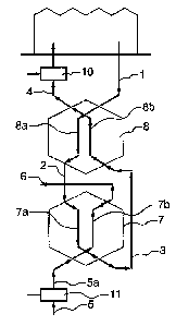
Figure 1 shows a simple diagram of the device according to the invention. The
device
comprises a first heat exchanger 7 embodied as an enthalpy recuperator. First
heat
exchanger 7 is provided with a first series of channels 7a and a second series
of
channels 7b coupled thermally thereto. The device also comprises a 'normal'
heat
exchanger 8, i.e. equipped only for exchanging sensible heat, which is
provided with a
first series of channels 8a and a second series of channels 8b coupled
thermally thereto.
The device further comprises a greenhouse supply connection 1 for supplying
air
originating from the greenhouse to the device, a greenhouse discharge
connection 4 for
discharging air from the device to the greenhouse, an outside supply
connection 5 for
supplying air originating from outside to the device, and an outside discharge
connection 6 for discharging air from the device to the outside.
In the heating position the air coming from the greenhouse is guided from the
greenhouse supply connection 1 to the first series of channels 8a of second 8
heat
exchanger. This air is then guided from the point 2 thus reached to first
series of
channels 7a of first heat exchanger 7, after which point 3 is reached and the
air is
carried to greenhouse discharge connection 4 via the second series of channels
8b of
second heat exchanger 8. The air coming from outside is guided from the
outside supply
connection 5 through the second series of channels 7b of first heat exchanger
7 and
subsequently guided outside again via the outside discharge connection 6.
As it passes through the first series of channels 8a of second heat exchanger
8 the air
coming from the greenhouse is cooled and condensed by the air flowing through
the
second series of channels 8b of the second heat exchanger. As it passes
through the first
series of channels 7a of the first heat exchanger the greenhouse air is
further cooled and
CA 02777640 2017-02-01
9
condensed from 2 to 3 by the preferably adiabatically cooled outside air
passing through
the second series of channels 7b of the first heat exchanger from 5 to 6. The
greenhouse
air is then heated again as it passes through 8b from 8 to 4 in the second
heat exchanger,
wherein use is made of the condensation heat during passage through 8a. By
making use
of the condensation heat the return temperature to the greenhouse has only
decreased by
a few percent, while the humidity has greatly decreased. Also shown in the
drawing are
humidifiers 10 and 11, which provide for the adiabatic humidification and
cooling of
the airflows. Fans can also be arranged at other locations in the relevant
paths of
respectively the greenhouse air and the outside air.
As shown in figure 2, during cooling operation both airflows follow a path
largely
corresponding to that of figure 1, with the proviso that the second series of
channels 8b
of second heat exchanger 8 is not passed through. Passage through the first
series of
channels 8a of second heat exchanger 8 hereby becomes pointless so that it is
also, or
alternatively, possible not to pass through the first series of channels 8a of
second heat
exchanger 8.
The thermodynamic operation of the invention is elucidated in an enthalpy
diagram as
shown in figures 3 and 4. Fig. 3 shows in an enthalpy diagram the situation
for the
heating position at different positions in the device for a regularly
occurring
combination of inside and outside temperature and relative humidity. The air
coming
from the greenhouse, the condition of which is designated with 1, is cooled
and
condensed and leaves the first series of channels 8a of second heat exchanger
8 in
condition 2 (the numerals correspond to those of figures 1 and 2). In the
first series of
channels 7a of first heat exchanger 7 this air is further cooled and condensed
to
CA 02777640 2017-02-01
condition 3. The greenhouse air is then heated again in second channels 8b of
second
heat exchanger 8 to almost the same temperature at which it entered the
device, but in a
much drier state, after which the condition 4 is achieved. The greenhouse air
can be
heated to such an extent because use can be made of the condensation heat, so
that the
5 temperature effectiveness lies close to 100%. The outside air is first
cooled adiabatically
from condition 5 to condition 5a. The outside air then heats up in the first
heat
exchanger and evaporates the condensation formed by the greenhouse air, and
leaves
the recuperator in condition 6.
10 In the cooling position the psychrometry or the thermodynamic process
takes place as
shown in fig. 4. The attempt is made here to achieve control to a constant
moisture
deficit of 4 g/m3, as indicated by the broken blue line. The greenhouse air in
condition 1
(the numbers correspond to fig. 2) is cooled in the first series of channels
7a of first heat
exchanger 7 and condensed to condition 3. In the outgoing greenhouse air or in
the
greenhouse water is atomized and entrained to the greenhouse via greenhouse
discharge
connection 4. This air mixes with the greenhouse air and reaches condition 4a,
while
solar energy is supplied and condition 4b is reached, wherein the water can
evaporate
and condition 4c is reached. In reality these processes take place
simultaneously,
although for purposes of explanation they are shown here successively in time.
Condition 4c coincides with the greenhouse air condition 1 after equilibrium
has been
reached. The outside air in condition 5 is cooled adiabatically to 5a. This
air is heated in
first heat exchanger 7, whereby the condensate formed by the greenhouse air
evaporates
and the air leaves the system in a condition 6. In this example the greenhouse
air in
condition 1 is the state of equilibrium at a gross irradiation of 500 Wm-2.
The other blue
points are always 100 Wm-2 less.
CA 02777640 2017-02-01
11
Given by way of comparison are the states of equilibrium of a greenhouse in
which
cooling takes place by opening the windows, this being curve through lb for a
tomato
crop and curve through la for a crop which evaporates only half the moisture
of that of
the tomato. It can be seen that the equilibrium temperature in the greenhouse
when the
windows are opened is several degrees lower than in the case of a closed
greenhouse
and use of the invention when a strongly evaporating crop is applied, up to
several
degrees higher if a less evaporating crop is applied. The great difference
between
application of the invention in a closed greenhouse and the opening of windows
is the
humidity, or the moisture deficit, which amounts to more than 15 when windows
are
opened and thereby falls outside the range considered optimal for healthy
growth.
Alternative embodiments of the cooling situation will now be elucidated with
reference
to figures 5 and 6.
In the heating position at least two recuperators are required to remove
moisture from
the greenhouse, without admixing of outside air, during simultaneous recovery
of the
heat released during cooling of the greenhouse air to below the condensation
point in
order to achieve the desired dehumidification. In addition to heat, an
enthalpy
recuperator also recovers moisture. During heating operation deeper cooling
can be
achieved in the second condensation step with an enthalpy recuperator because
the
condensation heat can be discharged as evaporation heat in the cooling
airflow, whereby
more moisture is discharged from the greenhouse air. Despite severe frost
outside, the
enthalpy recuperator cannot freeze. During cooling operation the enthalpy
recuperator
CA 02777640 2017-02-01
12
transfers moisture from the greenhouse air to the cooling air, whereby deeper
cooling of
the greenhouse air is achieved and the cooling capacity increases
considerably.
In the heating position an enthalpy recuperator serves no purpose in the first
condensation step since it is not the intention to re-humidify the returning
greenhouse
air. In the cooling position as according to figure 2 the recuperator is not
used, and an
enthalpy recuperator therefore serves no purpose here.
In the cooling position the first recuperator can however be used if the
diagram of figure
2 is extended with a number of plates so that flow through both recuperators
takes place
in parallel as shown in figure 5, whereby the flow resistance to both the
greenhouse air
and the outside (cooling) air decreases and the maximum flow, and thereby
cooling
capacity, increases using the same fan.
In this configuration it is possible to use no or one enthalpy recuperator
(together with
one recuperator for only sensible heat). If the enthalpy recuperator with
plates is
applied, both recuperators can also be enthalpy recuperators. In the heating
position the
switching time of the first enthalpy recuperator is then set to infinite, i.e.
no switching
takes place, so that the condensate runs out of the recuperator and is not
transferred to
the returning greenhouse air. In the cooling position the cooling capacity is
greatly
increased by the transfer of moisture from the greenhouse air to the outside
(cooling)
air. No condensation can however occur when a membrane recuperator is used. If
the
first recuperator is bypassed in the cooling position, a possible diagram will
appear as in
figure 6. This diagram requires only one three-way valve. If the recuperators
are
CA 02777640 2017-02-01
13
connected in parallel in the cooling position, the circuit diagram becomes
considerably
more complicated, as can be seen in figure 7.
The diagram enabling switching from the heating position to the cooling
position
requires a considerable number of two-way valves and a three-way valve (12 two-
way
valves and 1 three-way valve in this diagram). The number of two-way valves
can be
reduced by a good design of the path of the distribution channels in the
casing. The
three-way valve in figures 6 and 7 is modulating. A continuous transition from
the
heating position to the cooling position can hereby be achieved. This is only
possible if
the rest of the plates are in the heating position. Cooled greenhouse air 3 is
then
admixed with the reheated greenhouse air 4. As soon as the three-way valve has
reached
its final position, the other valves are placed in the cooling position.
A channel system with one or more plates is required in order to properly
guide the
flows of the greenhouse and the outside air through the two recuperators and
to enable
switching from heating to cooling operation. For practical and economic
reasons
channels and plates must be constructed in a casing which must result in the
least
possible flow loss at the lowest possible production price. The operating
members, such
as fans, humidifiers, pump, plate motors and control, can be integrated into
this casing
so that a compact, independently operating module results. Modules can then be
assembled to form larger units or be distributed over the greenhouse. It will
be apparent
that the modules can also be connected in parallel in a large casing.
The casing serves, among other purposes, to enable leakage-free connection of
the
recuperators to the integrated distribution channels for the air, to
accommodate the
CA 02777640 2017-02-01
14
distribution channels with the least possible flow loss, to provide a
topological solution
for intersecting distribution channels, to accommodate the plates for
switching from the
heating to the cooling position, to enable the use of the fewest possible
plates, to place
the fans such that the efficiency is high, to collect and discharge the
condensation water,
to accommodate the humidification of both the outside air and the greenhouse
air, to
provide connection to the supply and discharge channels of the greenhouse and
outside
air, this such that, if the casings are stacked or placed in parallel, a
simple configuration
of a super header or manifold suffices to connect the connections, to enable
stacking,
placing in parallel and fixing of units in precisely aligned manner, to enable
accommodation of the control electronics under the correct conditions, to
enable easy
mounting of the components and simple servicing of the system.
The plates must close well (total leakage <0.5% nominal flow) and they may
take up
only little space. A solution is to embody them as slide plates, wherein at
the end of the
closing movement they are pressed at a right angle to this movement into a
seal of the
plate seat by using the form of the guide rail. In the open position the
plates are parallel
to the closed surfaces of the recuperators so that no extra space is taken up.
Where
possible, the plates are connected to a rod mechanism so that the fewest
possible motors
are necessary for the linear movement. The three-way valve can be embodied as
rotating
valve.
The distribution channels must on the one hand take up as little space as
possible and on
the other be of a size such that the flow resistance is small relative to that
of the
recuperators. By placing two separated channels on the side of the
recuperator, wherein
the two channels can be connected to an inflow or outflow opening of the
recuperator,
CA 02777640 2017-02-01
inflow and outflow openings of the recuperators can be connected to each other
at
random. In order to allow all permutations, as is necessary for the diagram
with the
parallel recuperators in the cooling position, two parallel channels must be
arranged on
both sides of the recuperators. The slide plates are then operated such that
the desired
5 inflow and outflow openings of the recuperators are mutually connected.
This placing of
the distributing channels prevents the distribution channels intersecting each
other,
whereby more space would be necessary for the distribution channels.
The casing is preferably made such that the recuperators are enclosed by two
casing
10 parts at a time, wherein the casing parts are closed substantially at
right angles to
sealing flanges. In this way the seals between flange and casing are only
loaded in one
direction during mounting, whereby a very good sealing can be realized and the
mounting can also be carried out without positioning help. The casing parts
are
provided with a tongue and groove connection, which is embodied such that it
has a
15 clamping fit and is leakage-free. The mounting process is simplified by
making this
connection self-locating.
The casing parts preferably take a symmetrical form so that two casing
components can
be made with the same mould. The casing parts are preferably made such that
the
product can be removed from the mould in one direction so that no slides need
be used.
Applied for this purpose are closing parts which can fill the openings which
are
arranged for the purpose of symmetry but are not functionally necessary.
The slide plates are designed such that they can be mounted in the pulling
direction of
the casing parts by being pushed into the space recessed into the casing
parts, wherein a
CA 02777640 2017-02-01
16
good sealing is realized by cut edges. The casing is preferably made from a
foamed
plastic, whereby a good insulating value is achieved and a stable casing can
be formed.
Materials such as expanded polypropylene (EPP) are recommended here owing to
their
strength, insulating value, producibility, weight and price.
For the radial fans with backward curved blades which are the most suitable
for this
application, sufficient space is made round the blade wheel in order to thus
achieve the
highest possible fan efficiency.
At the inlet for the outside (cooling) air sufficient space is made to allow
evaporation of
a large part of the atomized water droplets, so that the air is cooled as far
as possible
adiabatically.
The casing is provided on both sides with a closing cover on which the fans,
the
electronics and the humidifiers are mounted. The covers and the casing parts
are
provided with a tongue and groove connection, as in the case of the casing
parts. The
outer side of the covers and the components of the channels of the manifolds
or super
headers are provided with a tongue and groove connection. These channel
components
are also provided with a tongue and groove connection. This creates a system
in which
the casing modules can be readily assembled to form a larger whole.
A preferably applied topology of the distribution channels and plates is
elucidated with
reference to figure 8. The basis is formed by a first and a second enthalpy
recuperator 7
and 8, which are placed mutually in line. A discharge channel 6 for
discharging outside
air extends along a discharge side of both recuperators 7, 8. A discharge
channel 4 for
CA 02777640 2017-02-01
17
discharging greenhouse air extends parallel to discharge channel 6, likewise
on the
discharge side of both recuperators 7, 8. The two recuperators 7, 8 are
mutually
connected by connecting channels 2, 3. A supply channel 1 for supplying the
outside air
extends parallel to the discharge channels on the supply side of recuperators
7, 8. A
supply channel 5 for supplying outside air likewise extends parallel to the
other
channels on the supply side of recuperators 7, 8. Plates b, c, d, e, f, g, h
and I are also
arranged, each between a recuperator 7, 8 and one of the respective channels
1, 4, 6, 7
and connecting channels 2, 3. These plates b, c, d, e, f, g, h and I are all
slide plates. A
valve a formed by a three-way valve is also arranged between channels 4 and 6
and
recuperator 8.
Plates b-1 are preferably embodied as slide plates with a mechanism to close
properly in
the closed position, as shown in figure 9. Plate 20 runs with protrusions 21
in a guide
track 22. Guide track 22 is placed such that plate 20 remains a short distance
from plate
frame 23 so that plate 20 can be moved reciprocally with very little friction.
Just before
the position where the plate must close the guide track runs toward the plate
frame at an
angle (-45'). At the end of the plate movement plate 20 is pressed with its
sealing 0-
ring (not shown in the drawing) against plate frame 23, thereby creating a
good seal
with negligible friction.
Plate 20 has in the centre a protrusion 24 to which can be attached a guide
rod 25 and 26
which can be connected to another plate. A protrusion around which a guide rod
can
rotate is made at right angles to the guide rail. This guide rod is also
connected to
protrusions 24 of two plates 20 lying one above the other, as shown in figure
10.
CA 02777640 2017-02-01
18
As shown in figure 10, the inner casing is the part of the casing which
connects directly
to the recuperators and in which a part of the guide rail fits. The inner
casing is drawn
here separately of the rest of the outer casing to enable the operation of the
plates to be
better seen in the drawings. The recuperators are also omitted here for the
sake of
clarity. Plates 20 are moved by a spindle motor. The plates are here connected
to each
other by guide rods 25 and 26, thereby saving on a number of motors. Plate a
is
embodied as rotating plate and is also moved on a rotation point by a spindle
motor. By
choosing the pitch of the worm drive such that the spindle is self-locking,
there remains
tension on the plates and the sealing is pressed down well, whereby leakage
will be
minimal. The spindle motor of the rotating plate a is rotatable on a rod
behind the plate
frame. The plates can of course move and be driven in other manner, although
with the
described plate system only three motors are necessary for ten plates. Some of
the ports
in the inner casing are only made to enable symmetrical embodiment of the
casing parts
and make them removable from the mould, whereby only two moulds are necessary.
They are closed by placing closing pieces therein.
In fig. lithe outer casing is added as line drawing so that the internal part
is still
visible. This drawing shows the inlet openings for the fans 30 and the spaces
in which
the fans can be placed. Finally, end covers 31 are added as shown in figure
12.
The heating function is usually fulfilled by a pipe heating system in the
greenhouse. The
heat is supplied here by a boiler or a combined heat and power system. The
heat can
also be supplied by a heat pump, wherein the heat can then be extracted from
the
already heated outside air and the fresh outside (cooling) air, so that more
dehumidification can also take place. The heat pump can then also be used to
cool the
CA 02777640 2017-02-01
19
outside (cooling) air in the cooling position and also to further cool the air
to the
greenhouse, while the heat is discharged with the heated outside air.
In the heating position heat is extracted from the already preheated and
humidified
outside air, wherein in addition to the sensible heat use is made of the
condensation heat
of the moisture transported out of the greenhouse. A high 'Coefficient Of
Performance'
(COP) can hereby be achieved.
In the cooling position the return air to the greenhouse is first cooled and
the outside
(cooling) air is then cooled with the heated medium. The recuperator hereby
produces
the maximum cooling by dehumidifying, and the greenhouse air is further
cooled.