Note: Descriptions are shown in the official language in which they were submitted.
CA 02778755 2012-04-24
WO 2011/052189 PCT/JP2010/006325
Description
Title of Invention: DOCUMENT HANDLER HAVING
VALIDATOR DETACHABLY ATTACHED THERETO
Technical Field
[0001] This invention relates to a document handler having a validator
detachably attached
thereto for validating documents inserted into validator, and a stacker for
storing
documents sent from validator.
Background Art
[0002] Figure 23 exemplifies a prior art bill handling apparatus mountable in
vending
machines, bill exchangers, automatic teller machines, automatic cash
dispensers and
gaming machines, and an example of such a bill handling apparatus is shown in
for
example U.S. Patent No. 5,372,361. A shown bill handling apparatus 100
comprises a
frame 111, a validator 101 secured to frame 111 for discriminating
authenticity of bills
inserted into validator 101, a stacker 3 detachably attached to frame 111.
Validator 101
comprises a conveyer device 102 for transporting a validated bill along a
passageway
107 to stacker 3. Stacker 3 comprises a case 106, a slit-like opening 110
formed in case
106 through which bills pass from an outlet 109 of passageway 107 of validator
101
into stacker 3, a chamber 108 formed in stacker 3 for temporarily retaining a
bill
therein, a storage 104 defined in case 106 for stowing bills therein, and a
pusher device
105 removably disposed within chamber 108 for pushing the bill in chamber 108
into
storage 104.
[0003] When stacker 3 is attached to frame 111, opening 110 of stacker 3 is
brought into
alignment with an outlet 109 of passageway 107 in conveyer device 102 to
connect
outlet 109 to opening 110, and simultaneously, a follower gear 113 is
automatically
brought into engagement with a drive gear 112 provided in conveyer device 102
which
directly drives follower gear 113.
[0004] When a control circuit (not shown in the drawings) in validator 101
decides an
inserted bill to be genuine, it drives conveyer device 102 so that the bill is
transported
along passageway 107 toward outlet 109. At the same time, as conveyer device
102
drives follower gear 113 through drive gear 112 in the forward direction,
follower gear
113 operates a carrier device (not shown in the drawings) in stacker 3 and
therefore,
the bill is moved by conveyer device 102 and carrier device through outlet 109
and
opening 110 into chamber 108 within case 106.
[0005] At this moment, conveyer device 102 is driven in the adverse direction
to reverse
drive gear 112 and follower gear 113 to thereby operate pusher device 105
which
forcibly pushes and stows the bill in chamber 108 into storage 104. During
forward
2
WO 2011/052189 PCT/JP2010/006325
rotation of drive and follower gears 112, 113, pusher device 105 is returned
to its
shown original position.
[0006] In the foregoing bill handling apparatus, when stacker 3 is attached to
frame 111,
follower gear 113 of pusher device 105 can automatically be brought into
engagement
with drive gear 112 of carrier device secured to frame 111. Not shown in
Figure 23,
but a shock absorber is provided in drive or follower gear 112, 113 to buffer
a me-
chanical shock occurring upon interlocking drive and follower gears 112 and
113.
[0007] Figure 24 shows a prior art structure for removably interlocking
validator 101 to
frame 111 by sliding validator 101 on frame 111 for fixing. As illustrated,
frame 111 is
formed with a pair of hooks 115 in a connecting structure 116 on its upper
surface, and
an opening 117 is formed on a bottom surface of validator 101. After sliding
movement of validator 101 on upper surface of frame 111, edges of opening 117
are
brought into engagement with hooks 115 to removably attach validator 101 to
frame
111 by sliding movement of validator 101 relative to frame 111. However, this
connecting structure 116 disadvantageously has a defect because when validator
101 is
mounted on frame 111 through the sliding movement, drive gear 112 of carrier
102 in
validator 101 naturally clashes with hooks 115 and therefore suffers a
mechanical
damage by the clash. Accordingly, hooks 115 have to be made of flexible
material
elastically deformable when drive gear 112 clashes with hooks 115. Also, as
connecting structure 116 includes hooks 115 for catching edge of opening 117
in
validator 101, it disadvantageously requires an increased height or additional
space for
bill handling apparatus to arrange connecting structure 116 therein. In this
case, if bill
handling apparatus is made in a larger size, it would be subject to
restriction in size by
standards, and therefore, volume in stacker 3 has to be made smaller in terms
of the
size in validator 101 and frame 111, and also, smaller stacker 3 cannot
accommodate
longer kinds of bills than chamber 108.
Summary of Invention
Technical Problem
[0008] Accordingly, an object of the present invention is to provide a
document handler
designed to detachably attach a validator thereto. Another object of the
present
invention is to provide a document handler designed to have a connector for
removably
attaching a validator to a frame in the fixed position without undesirable
physical
contact of a conveyer device in the validator to any other parts. A still
another object of
the present invention is to provide a document handler designed to detachably
attach a
validator to a frame in the fixed position for driving connection of a
conveyer device to
a carrier device and a pusher device in a stacker. A further object of the
present
invention is to provide a document handler to have a connector made up of a
cam
CA 02778755 2012-04-24
3
WO 2011/052189 PCT/JP2010/006325
guide and a follower in removable engagement with the cam guide formed as
config-
urations on side walls of a frame and a validator provided in the document
handler. A
still further object of the present invention is to provide a document handler
designed
to detachably attach a validator to a frame without need of any additional
device
between the validator and frame.
Solution to Problem
[0009] The document handler according to the present invention, comprises: a
frame (1)
having a pair of side walls (41) and a bracket (7) for connecting side walls
(41) of
frame (1), a validator (2) detachably attached to frame (1) and having a
conveyer
device (102), and a connector (4) for detachably attaching validator (2) to
frame (1).
Connector (4) comprises a cam guide (5) formed on at least one of side walls
(41) in
frame (1) or on at least one of side walls (51) in validator (2), and a
follower (6)
formed on at least one of side walls (51) in validator (2) or on at least one
of side walls
(41) in frame (1) to detachably bring follower (6) into engagement with cam
guide (5).
In this arrangement, validator (2) may be removably attached to the fixed
position in
frame (1) for easy exchange. Cam guide (5) comprises a distal path (10) for
guiding
movement of follower (6) to transport validator (2) in a spaced relation to
bracket (7),
and a access path (11) for guiding follower (6) to bring validator (2) to a
fixed position
after follower (6) has passed distal path (10). In mounting validator (2) to
frame (1) or
dismounting validator (2) from frame (1), distal path (10) of cam guide (5)
serves to
guide movement of follower (6) along distal path (10) without physical contact
of
conveyer device (102) in validator (2) to bracket (7) while averting
mechanical damage
to conveyer device (102). Also, as in the present invention, a slip-on
construction
between cam guide (5) and follower (6) in connector (4) is very advantageous
because
of prompt connection and separation of validator (2) relative to frame (1)
without any
additional part or arrangement.
[0010] Thus, the connector beneficially does not require any additional or
further device to
drivingly connect the validator and stacker without incurring increase in
height of the
document handler and without need of any additional arrangement because both
cam
guide and follower in the connector can be formed as configurations of both
side walls
in the frame and validator.
Brief Description of Drawings
[0011] The above-mentioned and other objects and advantages of the present
invention will
be apparent from the following description in connection with preferred
embodiments
shown in the accompanying drawings wherein:
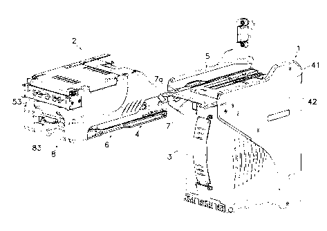
[fig. I] Figure 1 is a perspective view of a bill handling apparatus as a
document handler
according to the present invention with a validator removed from a frame;
CA 02778755 2012-04-24
4
WO 2011/052189 PCT/JP2010/006325
[fig.2]Figure 2 is a partial side elevation view of a cam guide formed on the
frame
shown in Figure 1;
[fig.3]Figure 3 is a partial side elevation view of a follower formed on the
validator
shown in Figure 1;
[fig.4]Figure 4 is a perspective bottom view of the validator;
[fig. 5 ]Figure 5 is a perspective top view of a stacker;
[fig.6]Figure 6 is a perspective view of a latch device for removably
fastening the
validator to the frame;
[fig.7]Figure 7 is a side elevation view of the latch device;
[fig.8]Figure 8 is a perspective view of the latch device in the released
condition of the
validator disengaged from the frame;
[fig.9]Figure 9 is a side elevation view of the latch device shown in Figure
8;
[fig. 10] Figure 10 is a side elevation view showing the follower of the
connector
inserted into a distal path of the cam guide;
[fig. 11] Figure 11 is a sectional view taken along a line XI-XI of Figure 10
demon-
strating a spaced relationship between drive and follower gears;
[fig.12]Figure 12 is a sectional view showing the follower inserted into a
access path;
[fig.13]Figure 13 is a sectional view showing the follower completely inserted
into the
fixed position of a proximal path in the cam guide;
[fig. 14] Figure 14 is a partially sectional enlarged view of the follower in
the fixed
position;
[fig.15]Figure 15 is a sectional view taken along a line XV-XV in Figure 13
demon-
strating the interlocked drive and follower gears;
[fig.16]Figure 16 is a sectional view showing a second embodiment of the
present
invention with a cam guide formed on a validator;
[fig.17]Figure 17 is a sectional view showing the second embodiment of the
present
invention with a follower formed on a frame;
[fig.18]Figure 18 is a side elevation view showing the engaged follower and
cam guide
in the second embodiment;
[fig.19]Figure 19 is a sectional view of drive and follower gears in the
spaced relation
in the second embodiment;
[fig.20]Figure 20 is a sectional view taken along a line XX-XX of Figure 18
showing
the engaged drive and follower gears in the second embodiment;
[fig. 2 1 ]Figure 21 is a perspective exploded view of a third embodiment of
the bill
handling apparatus according to the present invention;
[fig.22] Figure 22 is a block diagram of a cam guide and a follower according
to the
third embodiment of the present invention;
[fig.23]Figure 23 is a simplified sectional view of a prior art bill handling
apparatus;
CA 02778755 2012-04-24
5
WO 2011/052189 PCT/JP2010/006325
and
[fig.24]Figure 24 is a simplified sectional view of another prior art bill
handling
apparatus.
Description of Embodiments
[0012] Described hereinafter in connection with Figures 1 to 22 of the
drawings will be em-
bodiments of a bill handling apparatus as a document handler according to the
present
invention. In the description herein, a word "front" or "foreside" denotes the
forward
part or left hand in Figure 13 of a bill validator 2 involving a bill inlet 53
on an X-axis,
a wording "back" or "rear side" denotes the hind part or right hand in Figure
13 of bill
validator 2 on X-axis. A word "top" or "upside" denotes the upward part of
bill
validator 2 on a Y-axis, and a word "bottom" or "downside" denotes the
downward
part of bill validator 2 on Y-axis. All words "detachable", "removable" and
"separable"
indicate the same meaning of "demountable".
[0013] As seen from Figure 1, the bill handling apparatus according to the
present invention,
comprises: a frame 1, a validator 2 detachably attached to frame 1, a
connector 4
provided between frame 1 and validator 2 for detachably attaching validator 2
to frame
1, and a stacker 3 detachably attached to frame 1 for stowing therein bills
transported
from validator 2. In the shown embodiment in Figure 1, frame 1 has a pair of
side
walls 41, a rear wall 42 for connecting each rear part of side walls 41, and a
bracket 7
bridged and connecting front portions of side walls 41. Connector 4 comprises
cam
guides 5 formed on a pair of vertically disposed side walls 41 in frame 1, and
followers
6 formed on a pair of vertically disposed side walls 51 in validator 2 so that
followers 6
may be inserted into mating cam guides 5 for attachment of validator 2 to
frame 1.
Bracket 7 is horizontally disposed at a right angle and connected to side
walls 41 in
frame 1. A latch device 8 is disposed at the front end of validator 2 between
validator 2
and bracket 7 to securely fasten validator 2 to bracket 7 to prevent
contingent
movement of validator 2 in the withdrawal direction. Frame 1, each outer cell
of
validator 2 and stacker 3 may be formed by injection molding of a resin
material
selected from the group consisting of ABS resin, polycarbonate resin, acrylic
resin,
polyamide resin, polyacetal resin and any mixed compound of these resins or by
press
forming of metallic plates such as aluminum, iron or any alloy of these
metals. Ac-
cordingly, connector 4 may be formed of molding resin, forming metal or
combined
material of resin and metal.
[0014] In an embodiment shown in Figure 2, each cam guide 5 comprises a
horizontal distal
path 10 formed on side wall 41 in frame 1, an aslope access path 11 connected
to a
bottom of distal path 10, and a horizontal proximal path 12 connected to a
bottom of
access path 11. Distal path 10 comprises a distal surface 13 formed opposite
to bracket
CA 02778755 2012-04-24
6
WO 2011/052189 PCT/JP2010/006325
7, a ridged surface 14 protruded toward distal surface 13 and an inlet incline
19 formed
in front of ridged surface 14. Access path 11 is formed between distal and
proximal
paths 10 and 12 to comprise a back ramp 15 connected to distal surface 13 and
an
anterior ramp 16 connected to ridged surface 14 and disposed in parallel to
back ramp
15. Proximal path 12 comprises a proximal surface 20 continuously extending
from
anterior ramp 16 and disposed in parallel to distal surface 13, a latch
surface 21 con-
tinuously extending from back ramp 15 and disposed in parallel to distal
surface 13,
and an innermost surface 22 formed between proximal and latch surfaces 20 and
21.
Bracket 7 is attached and secured to frame 1 in front of inlet incline 19 to
define an
inlet 23 of distal path 10 in cooperation with distal surface 13.
[0015] Follower 6 comprises a proximal flat 31, a distal flat 32 formed in
parallel to and in
upwardly spaced relation to proximal flat 31, an intermediate ramp 36
connected to
proximal flat 31 and disposed in parallel to anterior ramp 16, an intermediate
flat 33
connected to intermediate ramp 36 and disposed in parallel to and in upwardly
spaced
relation to proximal flat 31, a complementary ramp 37 connected to
intermediate flat
33, a base flat 34 connected to complementary ramp 37 and disposed in parallel
to and
in downwardly spaced relation to intermediate flat 33, a stabilizing ramp 38
connected
to distal flat 32 and disposed in parallel to intermediate ramp 36, and an
anterior flat 35
connected to stabilizing ramp 38 and disposed in parallel to and in upwardly
spaced
relation to distal flat 32, a rising 25 formed at an end of anterior flat 35
to come into
contact to or confrontation with an edge 24 of inlet 23 in distal path 10 when
follower
6 is inserted into cam guide 5, and an arcuate end surface 39 connecting
proximal and
distal flats 31 and 32. Arcuate end surface 39 has a complementary arcuate
shape to
that of innermost surface 22 of proximal path 12.
[0016] Figures 4 illustrates a pair of drive gears 26 rotatably mounted in
validator 2 and
driven by conveyer device 102 used to transport a bill through passageway in
validator
2 shown in Figure 23. Drive gears 26 make up a part of conveyer device 102 and
a
bottom part of drive gears 26 downwardly projects beneath a horizontally
disposed
bottom surface 52 of validator 2. Figure 5 demonstrates a pair of follower
gears 27 for
driving a carrier device (not shown in the drawings) and pusher device 105 in
stacker
3. For example, when moved to the innermost of proximal path 12 to bring
arcuate end
surface 39 of follower 6 into contact to innermost surface 22 of proximal path
12,
follower 16 is in the proper fixed position for fixing validator 2 in position
to frame 1
with respect to stacker 3 as shown in Figures 13 and 14, while drive gears 26
are si-
multaneously brought into engagement with follower gears 27 to directly drive
follower gears 27 through drive gears 26. Here, as seen from Figure 4, formed
on a
bottom surface 52 of validator 2 are a laterally elongated outlet 55 of a bill
passageway
in validator 2, and openings 57 through which drive gears 26 of conveyer
device 102
CA 02778755 2012-04-24
7
WO 2011/052189 PCT/JP2010/006325
protrude outside of bottom surface 52. Drive gears 26 are in engagement with
follower
gears 27 to drive carrier device and a pusher device 105 in stacker 3 to
transport bill
through an inlet 63 to a predetermined standby position in chamber 108 during
operation of carrier device and also to stow bill from the standby position to
a storage
position in stacker 3 during operation of pusher device 105. By way of
example,
forward and adverse rotations of drive gears 26 respectively and separately
drive
carrier device and pusher device 105. For example, carrier device may have a
one-way
rotation clutch for preventing adverse rotation of carrier device during
adverse rotation
of drive gears 26. To this end, at least a bottom part of drive gears 26 is
downward
beyond bottom surface 52 in openings 57 to bring them into driving engagement
with
follower gears 27.
[0017] Bottom surface 52 of validator 2 is also formed with a plurality of
protective ridges
58 that downward project toward stacker 3 around drive gears 26 from bottom
surface
52. Projection length of protective ridges 58 from bottom surface 52 is
substantially the
same as or more than that of drive gears 26 to completely surround drive gears
26 by
protective ridges 58. Protective ridges 58 extend in parallel to each other
and perpen-
dicularly to outlet 55 of bill passageway. As shown in Figure 5, a top surface
62 of
stacker 3 comprises inlet 63 for receiving bill transported from validator 2,
a plurality
of or four inwardly hollow and straight grooves 64 extending lengthwise or
perpen-
dicularly to inlet 63 and in parallel to each other, and ridges 65 formed on
top surface
62 between each follower gear 27 and each groove 64. When mounting validator 2
to
frame 1, bottom surface 52 of validator 2 comes to be disposed in parallel to
top
surface 62 of stacker 3, and at the same time, drive gears 26 of validator 2
become
meshed with follower gear 27 of stacker 3; protective ridges 58 of validator 2
come
into interlocked engagement with mating grooves 64 of stacker 3; drive gears
26 and
protective ridges 58 of validator 2 are located to sandwich ridges 65 of
stacker 3
therebetween; and outlet 55 of validator 2 is rendered properly aligned with
inlet 63 of
stacker 3.
[0018] As shown in Figures 6 to 9, latch device 8 of validator 2 comprises a
ratchet lever 81
rotatably mounted on bracket 7 around a shaft 84, a rotatable operation lever
82
secured on an axis 88, a handle 83 secured on axis 88 and a tensile spring 86
having
one end secured to side wall 51 of validator 2 (Figures 7 and 9) and the other
end
connected to a biased end 89 of ratchet lever 81 to produce a tensile elastic
force for
resiliently urging ratchet lever 81 in the counterclockwise direction of
rotation around
shaft 84. Ratchet lever 81 comprises a stopper 85 formed with a lever slant
85a which
may be caught by an edge of an opening 7a formed on bracket 7, and an
elongated hole
90 for rotatably receiving a pin 87 secured on operation lever 82. When
validator 2 is
mounted on frame 1, stopper 85 slides on an upper surface of bracket 7 with
lever slant
CA 02778755 2012-04-24
8
WO 2011/052189 PCT/JP2010/006325
85a in contact to bracket 7, and therefore, lever slant 85a forcibly rotates
ratchet lever
81 in the clockwise direction against resilient force of tensile spring 86.
When handle
83 is manually withdrawn downward, ratchet lever 81 is also forcibly rotated
in the
clockwise direction to release engagement of stopper 85 from opening 7a.
[0019] As seen from Figures 10 and 11, when validator 2 is installed in the
fixed position of
frame 1, end surface 39 of follower 6 is inserted into inlet 23 of distal path
10 and is
brought into contact to inlet incline 19 to guide end surface 39 upward along
inlet
incline 19 onto ridged surface 14. Then, proximal flat 31 of follower 6 is in
contact to
and slides on ridged surface 14 to simultaneously bring distal flat 32 of
follower 6 to
face or be in contact to distal surface 13 of distal path 10, and then
proximal flat 31 is
inwardly moved along and in sliding contact to distal path 10. In other words,
follower
6 is traveled toward the rear of frame 1 in upwardly spaced relation from
stacker 3 by a
height of ridged surface 14 over bracket 7. Although bottom parts of drive
gears 26 and
protective ridges 58 are located to project from bottom surface 52 of
validator 2, it is
possible to prevent unfavorable contact of these bottom parts to bracket 7 and
upper
surface 62 of stacker 3 while moving follower 6 rearward, because proximal
flat 31 of
follower 6 is in contact to ridged surface 14 of cam guide 5 to space these
bottom parts
from bracket 7 and upper surface 62 as shown in Figures 10 and 11.
[0020] When validator 2 is further inwardly pushed into the rear of distal
path 10 from the
position shown in Figure 10, as illustrated in Figure 12, end surface 39 of
follower 6
comes into contact to back ramp 15 to concurrently put intermediate ramp 36 of
follower 6 in touch with and slides on anterior ramp 16 so that the whole of
follower 6
and validator 2 is moved downwardly toward stacker 3 along access path 11
defined by
back and anterior ramps 15 and 16 on the angle shown by an oblique arrow in
Figure
12. Immediately when follower 6 reaches proximal path 12, proximal flat 31 of
follower 6 is brought into contact to proximal surface 20, and simultaneously,
drive
gears 26 and protective ridges 58 are brought into engagement with
respectively
follower gears 27 and mating grooves 64.
[0021] Then, validator 2 is further pushed toward the rear of proximal path
12, follower 6
horizontally moves along proximal path 12 of cam guide 5 by a small distance,
and
finally end surface 39 of follower 6 comes into contact to innermost surface
22 of
proximal path 12 to completely put validator 2 in the proper fixed position,
at the same
time to bring drive gears 26 into secure engagement with follower gears 27 and
also to
prevent further forward movement of follower 6 as shown in Figures 13 to 15.
Also,
complementary ramp 37 of follower 6 is in contact to or faces inlet incline
19, and
rising 25 of follower 6 faces or is in contact to edge 24 of inlet 23, but a
gap is formed
between intermediate ramp 36 of follower 6 and anterior ramp 16 of cam guide 5
as
shown in Figure 13. Alternatively, drive gears 26 may be in driving connection
with
CA 02778755 2012-04-24
9
WO 2011/052189 PCT/JP2010/006325
follower gears 27 at the time of contact of proximal flat 31 to proximal
surface 20 once
end surface 39 reaches proximal path 12, and a spring or elastic medium for
producing
elastic buffer action may be used in at least one of interlocked drive and
follower gears
26 and 27.
[0022] In this way, according to the bill handling apparatus of the present
invention, when
validator 2 is mounted on frame 1, follower 6 may be fit into and slid on
ridged surface
14 along distal path 10 of cam guide 5 toward the fixed position of validator
2 while
preventing undesirable impact of drive gears 26 in validator 2 with bracket 7
and upper
surface 62 of stacker 3. This also ensures that validator 2 can be safely
horizontally
moved over, in parallel relation to and relative to top surface 62 of stacker
3 while
maintaining conveyer device 102 in a spaced relation from bracket 7 and
stacker 3.
After that, follower 6 can be moved at an angle along access path 11 while
moved
closer to stacker 3 and finally follower 6 reaches proximal path 12 while
proximal flat
31 of follower 6 comes into contact to proximal surface 20 of cam guide 5.
After
follower 6 reaches proximal path 12, it is further moved horizontally to the
proper
fixed position for validator 2 by the slight backward distance, and therefore,
drive
gears 26 of validator 2 are directly meshed with follower gears 27. Also, when
follower 6 enters proximal path 12, protective ridges 58 on bottom surface 52
of
validator 2 can be fit into mating grooves 64 on top surface 62 of stacker 3,
and
moreover, outlet 55 of validator 2 comes in perfect register with inlet 63 of
stacker 3
while validator 2 can correctly be put in the proper fixed position of frame
1.
[0023] In this embodiment, connector 4 can be made as outer formative
configurations of
frame 1 and validator 2 without need of any additional component or prior art
connector between cam guide 5 and follower 6, and therefore, the bill handling
apparatus may increase height and length in stacker 3 to expand its content
for accom-
modating bills therein. Also, as stacker 3 may have its extended length, it
can receive
longer bills prior art stackers cannot stow, and obviously this widens
application
ranges of bill handling apparatus. Although follower gears 27 of stacker 3 are
located
within stacker 3 not to project beyond top surface 62 of stacker 3, validator
2 can be
mounted on frame 1 in a predetermined fixed position while protecting drive
gears 26
of validator 2 against undesirable collision with externals upon attachment
and de-
tachment operation of validator 2 with respect to frame 1, thereby extending
service
life of the bill handling apparatus.
[0024] As shown in Figure 12, when follower 6 is moved along distal path 10,
lever slant
85a of stopper 85 in latch device 8 is brought into contact to an edge 7b of
bracket 7
(Figure 7) to forcibly rotate latchet lever 81 in the clockwise direction
around shaft 84
against elastic force of spring 86, and therefore stopper 85 runs on and moves
sliding
on upper surface of bracket 7. Then, follower 6 is moved down at a slant along
back
CA 02778755 2012-04-24
10
WO 2011/052189 PCT/JP2010/006325
and anterior ramps 15, 16 through access path 11 during which stopper 85
remains in
contact with upper surface of bracket 7. When end surface 39 of follower 6 is
brought
into contact to innermost surface 22 of proximal path 12, elastic force of
spring 86
rotates latchet lever 81 in the counterclockwise direction to engage stopper
85 in
opening 7a of bracket 7 so that latch device 8 serves to set validator 2 in
the fixed
position of frame 1 and also to certainly prevent abrupt withdrawal of
validator 2 from
frame 1. In this way, cam guides 5 and mating followers 6 provide a slip-on
con-
struction for promptly and easily mounting validator 2 on frame 1 without
producing
any mechanical collision therebetween.
[0025] When validator 2 is removed from frame 1, handle 83 is manually rotated
downward
against resilient force of spring 86 to rotate latchet lever 81 upward in the
clockwise
direction through pin 87 as handle 83 is rotated in the counterclockwise
direction
around axis 88. Clockwise rotation of latchet lever 81 releases engagement
between
stopper 85 and opening 7a to allow validator 2 to be pulled forward so that
followers 6
can be separated from cam guides 5 to remove validator 2 from frame 1 without
un-
desirable physical contact of conveyer device 102 in validator 2 to bracket 7
and upper
surface 62 of stacker 3.
[0026] The first embodiment shown in Figures 1 to 15 illustrates a structure
of connector 4
having cam guides 5 formed on inner surfaces of side walls 41 in frame 1 and
followers 6 formed on a pair of side walls 51 in validator 2. Otherwise, as in
a second
embodiment shown in Figures 16 to 20, vice versa followers 6 may be formed on
inner
surfaces of side walls 41 in frame 1, and cam guides 5 may be formed on a pair
of side
walls 51 in validator 2. It should be understood from the foregoing
description that the
second embodiment would produce essentially similar operations and effects as
those
of the first embodiment. Same symbols as those of the first embodiment shown
in
Figures 1 to 15 are used to denote similar or identical parts in the second
embodiment.
[0027] Figures 21 and 22 represent a third embodiment of the bill handling
apparatus
according to the present invention. Same symbols are used in Figures 21 and 22
to
indicate substantially the same as or similar parts to those in Figures 1 to
20. Unlike
the first and second embodiments, the third embodiment has a simplified
structure as
shown in Figures 21 and 22 by removing distal surface 13 and back ramp 15 from
cam
guide 5 and also by forming cross-section shape of follower 6 into a
simplified shape
of generally a trapezoid or parallelogram. However, it would be apparent to
ordinary
skill in the art that the third embodiment has the basically same construction
as those in
the first and second embodiments to produce equivalent functions and effects.
The
shown third embodiment has frame 1 formed with cam guide 5 and validator 2
formed
with follower 6, however, vice versa as shown in Figures 16 to 18, follower 6
may be
formed in frame 1, and cam guide 5 may be formed in validator 2.
CA 02778755 2012-04-24
11
WO 2011/052189 PCT/JP2010/006325
[0028] The foregoing embodiments according to the present invention may be
varied in
various ways. For example, bracket 7 is described as connected between side
walls 41
of frame 1 for improvement in rigidity of frame 1, however, discrete bracket 7
from
frame 1 or integral bracket 7 with frame 1 may be secured between side walls
41 of
frame 1. Frame 1 may use a roof plate of stacker 3 attached to frame 1 as a
substitute
for bracket 7. The present invention is also applicable to a bill handling
apparatus of
inverted structure with validator detachably attached to frame under stacker.
The bill
handling apparatus may use only a couple of a cam guide 5 and a follower 6
formed on
either side wall 51 of validator 2 and mating side wall 41 of frame 1.
[0029] Embodiments according to the present invention produce the following
effects:
[1] Validator 2 may be attached to and detached from frame 1 for easy
replacement;
[2] Connector 4 allows to attach validator 2 to frame 1 and detach validator 2
from
frame 1 without undesirable physical contact of conveyer device 102 in
validator 2 to
any other parts including bracket 7 and upper surface 62 of stacker 3;
[3] Validator 2 may be mounted on frame 1 in the fixed position for driving
connection of conveyer device 102 to carrier device and pusher device 105 in
stacker
3;
[4] Connector 4 may comprise cam guide 5 and follower 6 removably connectable
each other;
[5] Cam guide 5 and follower 6 in connector 4 may be formed as outer formative
configurations in frame 1 and validator 2 without need of any additional or
further
connection device;
[6] Connector 4 does not increase the height in the bill handling apparatus,
and so
stacker 3 may have its increased height or length to expand its volume for
accom-
modating more or larger bills;
[7] Protective ridges 58 may certainly guard drive gears 26 exposed from
bottom
surface 52 of validator 2 against their mechanical damage by collision.
Industrial Applicability
[0030] This invention is applicable to a bill handling apparatus having a
validator detachably
attached thereto to validate valuable documents, valuable paper, coupons, bank
notes,
security, tender, token or scrip other than bills.
CA 02778755 2012-04-24