Note: Descriptions are shown in the official language in which they were submitted.
CA 02778804 2012-05-30
RETRACTABLE SAFETY BARRIERS AND METHODS OF OPERATING SAME ,/
Field of the Disclosure
[0002] This disclosure relates generally to retractable safety barriers and,
more
specifically, to retractable safety barriers for loading dock platforms and
the like.
Background
[0003] Many retractable safety barriers for doorways have been developed to
help prevent
children and pets from entering certain areas. To selectively open or block a
doorway, some
barriers include a rollup panel that can be unrolled to extend across and
block the doorway.
When not in use or to allow passage, the panel can wrap about a roller for
storage along one
side of the doorway. A few examples of retractable barriers with rollup panels
are disclosed
in U. S. Patents 5,636,679; 5,690,317; 6,536,502; 5,505,244; and 6,056,038.
[0004] Once such a rollup panel is extended across a doorway, usually some
type of
locking mechanism helps prevent the panel from unwrapping any farther so that
the child or
pet is unable to force the panel open. Such locking mechanisms typically
include a little tab
or pawl that engages a ratchet or some other type of tooth or slotted wheel,
which in turn is
coupled to the roller about which the panel is wrapped. The tab or pawl
engaging the wheel
hopefully prevents the roller from releasing the panel any farther. This may
work well for
light duty applications involving children and pets; however, such barriers do
not appear
adequate for industrial applications.
[0005] In factories, for example, a forklift and other material handling
equipment may
need to travel near operating equipment such as machine tools (machining
centers, turning
centers, etc.). A permanent guardrail may prevent a forklift from striking the
machine, but
the guardrail may also interfere with material handling equipment trying to
load and unload
the machine of its work pieces. While a permanent guardrail may be effective
at preventing a
- 1 -
CA 02778804 2012-05-30
forklift from striking a machine, forklift impact with a traditional, rigid
guardrail often results
in significant and permanent damage to the guardrail.
[0006] Truck loading docks may also have a need for a retractable barrier. A
barrier may
help prevent dockworkers and material handling equipment from accidentally
falling off the
edge of the dock's elevated platform. The platform's height is about the same
as that of an
average truck bed. Although a door typically exists at the edge of the
platform, the door's
strength may be insufficient to withstand the impact of a forklift, or the
door may be left open
for various reasons. The door, for instance, may be left open simply because
the weather is
nice, and the workers inside would like to enjoy some fresh air. With the door
open,
however, the loading dock platform may create a safety problem.
[0007] Although costly massive safety gates have been used at loading docks,
they can
take up a lot of space even when they are opened to allow passage through the
doorway.
Even though they may be able to stop a slowly moving forklift, an impact can
cause
considerable damage to the gate due to the gate's limited ability to
resiliently absorb the
impact. Also, permanent or other conventional guarding may not be suitable for
loading dock
areas, as such guarding may interfere with operating the door, loading and
unloading trucks,
and operating a dock leveler that may be installed at the platform.
[0008] A dock leveler is often installed at the loading dock platform to
compensate for a
height difference that may exist between the platform and the bed of the
truck. A dock
leveler typically includes a deck that is hinged at its back edge to raise or
lower its front edge
to generally match the height of the truck bed. Often an extension plate or
lip is pivotally
coupled to the deck to bridge the gap between the deck's front edge and a back
edge of the
truck bed. The deck and extended lip provide a path for forklifts to travel
between the
loading dock platform and the truck bed, thus facilitating loading or
unloading of the truck.
Unfortunately, a conventional barrier or guardrail extending over the dock
leveler may
restrict the deck's upward pivotal motion.
[0009] Since a dock leveler and the adjacent door move in the area where
guarding may be
needed, it becomes challenging to provide the area with a barrier that is
movable yet
sufficiently strong to impede heavy material handling equipment. Moreover,
some
installations require a removable guardrail that can cover a particularly long
span without
intermediate support posts. Covering such a span, however, can make it
difficult for a single
person to manually extend and retract a long flexible barrier.
- 2 -
CA 02778804 2012-05-30
Brief Description of the Drawings
[0010] FIG. 1 is a perspective view of an example retractable barrier in an
open or stored
position.
[0011] FIG. 2 is a perspective view of the retractable barrier of FIG. 1 but
showing the
barrier partially open.
[0012] FIG. 3 is a perspective view of the retractable barrier of FIG. 1 but
showing the
barrier in a blocking position.
[0013] FIG. 4 is a cross-sectional view taken along line 4-4 of FIG. 1.
[0014] FIG. 5 is a cross-sectional view taken along line 5-5 of FIG. 3.
[0015] FIG. 6 is a cross-sectional view similar to FIG. 5 but showing the
panel
experiencing an impact.
[0016] FIG. 7 is a cross-sectional view similar to FIG. 5 but with the barrier
being set for a
narrower doorway.
[0017] FIG. 8 is a cross-sectional view similar to FIG. 5 but with the
location of the
barrier's two support members being interchanged.
[0018] FIG. 9 is a cross-sectional view taken along line 9-9 of FIG. 10.
[0019] FIG. 10 is a front view of another example of a retractable barrier.
[0020] FIG. 11 is a top view of FIG. 12.
[0021] FIG. 12 is a front view of another example of a retractable barrier.
[0022] FIG. 13 is a front view of another example of a retractable barrier.
[0023] FIG. 14 is a front view of another example of a retractable barrier.
[0024] FIG. 15 is a top view of an example retractable barrier being extended
to a second
support member from an open or stored position on a first support member.
[0025] FIG. 16 is a front view of FIG. 15.
[0026] FIG. 17 is a top view similar to FIG. 15 but showing the barrier being
tightened and
locked in placed.
[0027] FIG. 18 is a front view of FIG. 17.
[0028] FIG. 19 is a cross-sectional view taken along line 19-19 of FIG. 18.
[0029] FIG. 20 is a front view of another example of a retractable barrier.
[0030] FIG. 21 is a front view of a post with a bracket mounted to it.
[0031] FIG. 22 is a side view of FIG. 21.
[0032] FIG. 23 is a schematic top view showing various configurations of an
example
modular barrier system.
-3 -
CA 02778804 2012-05-30
[0033] FIG. 24 is a cross-sectional front view of another example barrier
system.
[0034] FIG. 25 is a top view of the barrier system of FIG. 24 being tightened.
[0035] FIG. 26 is a top view similar to FIG. 25 but with the system already
tightened.
[0036] FIG. 27 is a cross-sectional front view of alternate example barrier
system similar
to that of FIG. 24.
[0037] FIG. 28 is a top view of the barrier system of FIG. 27 being tightened.
[0038] FIG. 29 is a top view similar to FIG. 27 but with the system already
tightened.
[0039] FIG. 30 is a front view of a barrier system in its extended position.
[0040] FIG. 31 is a front view of the barrier system of FIG. 30 but showing
the barrier
being moved between its extended and retracted positions.
[0041] FIG. 32 is a top view showing the barrier of FIG. 30 being tightened.
[0042] FIG. 33 is a cross-sectional front view of an example motorized barrier
system.
[0043] FIG. 34 is a top view of the barrier system of FIG. 33 being tightened.
[0044] FIG. 35 is a top view similar to FIG. 34 but showing the system already
tightened.
[0045] FIG. 36 is a front cross-sectional view of an example barrier system in
a de-
activated position.
[0046] FIG. 37 is a front cross-sectional view similar to FIG. 36 but showing
the system in
the activated position.
[0047] FIG. 38 is a top view of an example barrier system with its barrier
retracted.
[0048] FIG. 39 is a front view of FIG. 38.
[0049] FIG. 40 is a top view of an example barrier system with its take-up
member tilted
sideways.
[0050] FIG. 41 is a front view of FIG. 40.
[0051] FIG. 42 is a top view of an example barrier system with its barrier
partially
extended.
[0052] FIG. 43 is a front view of FIG. 42.
[0053] FIG. 44 is a top view of an example barrier system with its take-up
member laid
over and its barrier extending slack between two support members.
[0054] FIG. 45 is a front view of FIG. 44.
[0055] FIG. 46 is a top view of an example barrier system with its take-up
member upright
and its barrier extending slack between two support members.
[0056] FIG. 47 is a front view of FIG. 46.
[0057] FIG. 48 is a top view similar to FIG. 46 but with its barrier partially
tightened.
- 4 -
CA 02778804 2012-05-30
[0058] FIG. 49 is a front view of FIG. 48.
[0059] FIG. 50 is a top view similar to FIG. 46 but with its barrier fully
tightened.
[0060] FIG. 51 is a front view of FIG. 50.
[0061] FIG. 52 is a top view of an example barrier system with its barrier
being wound up.
[0062] FIG. 53 is a front view of FIG. 52.
[0063] FIG. 54 is a top view of the support member of FIG. 38 but shown in
another
configuration.
[0064] FIG. 55 is a front view of two example retractable barriers coupled to
each other at
an intermediate point between two support members.
[0065] FIG. 56 is a top view of an example barrier system method at a loading
dock.
[0066] FIG. 57 is a top view similar to FIG. 56 but showing the barrier
guarding one side
of the vehicle bed.
[0067] FIG. 58 is a top view similar to FIG. 57 but showing the barrier system
set up to
guard one side plus the back end of the vehicle bed.
Detailed Description
[0068] Certain examples are shown in the above-identified figures and
described in detail
below. In describing these examples, like or identical reference numbers are
used to identify
common or similar elements. The figures are not necessarily to scale and
certain features and
certain views of the figures may be shown exaggerated in scale or in schematic
for clarity
and/or conciseness. Additionally, several examples have been described
throughout this
specification. Any features from any example may be included with, a
replacement for, or
otherwise combined with other features from other examples.
[0069] The methods and apparatus described herein may be advantageously used
as a
movable, heavy-duty industrial barrier. The methods and apparatus described
herein are
significantly more compact in the stored position as compared to known
guardrails.
Additionally, the methods and apparatus described herein are capable of being
impacted by
material handling equipment without significant damage. Further, the methods
and apparatus
described herein are relatively easy to operate single handedly and, are more
cost-efficient to
implement as compared to known guardrails.
[0070] A retractable safety barrier 10 that may be advantageously used in
heavy duty
industrial applications is shown in FIGS. 1 ¨ 3. The figures show a view from
within a
building looking out through an open doorway 12. FIG. 1 shows barrier 10 in an
open stored
- 5 -
CA 02778804 2012-05-30
position, FIG. 3 shows barrier 10 in a blocking position, and FIG. 2 shows
barrier 10 partway
between its open and blocking positions.
[0071] Although barrier 10 is particularly well suited for installation on an
elevated
platform 14 of a loading dock 16, barrier 10 can be readily applied to a broad
range of heavy
and light duty applications including, but not limited to, guarding machinery,
guarding
construction sites, restricting vehicular and pedestrian traffic, restraining
cargo, restraining
stock stored on high pallet racks, etc. Since the structure and function of
various examples of
barrier 10 may be similar regardless of the barrier's specific application,
barrier 10 will be
described with reference to its installation at loading dock 16.
[0072] Loading dock 16 may include a conventional dock leveler 18 whose
pivotal deck
20 is presently shown at its cross-traffic position where the top surface of
deck 20 is generally
flush with platform 14. Loading dock 16 also includes a door 22 that can
provide access to a
truck parked at the loading dock 16. When a truck is not present, door 22 is
normally closed
and the need for barrier 10 may not be apparent; however, the strength of door
22 may be
insufficient to withstand the impact of a forklift. In some cases, door 22 may
be left open, as
shown, even though no truck is present. If the weather outside is mild, for
instance, door 22
may be left open to help ventilate the building.
[0073] Whether door 22 is open or closed while no truck is present at the
loading dock 16,
dock leveler 18 may create a falling hazard. A dockworker or material-handling
vehicle,
such as a forklift, may accidentally travel off the edge of platform 14 and
fall onto the
driveway just beyond doorway 12. To help prevent such an accident, some type
of barrier
could be installed across the doorway. The barrier, however, should preferably
be movable
to permit loading or unloading a truck at the loading dock 16, not interfere
with the operation
of the door 22, permit the operation of the dock leveler 18, and not obstruct
traffic in the
vicinity of the loading dock 16.
[0074] In one example implementation, barrier 10 comprises a retractable panel
24 that can
selectively extend and retract between two support members, which will be
referred to as a
first support member 26 and a second support member 28. Support members 26 and
28 may
be attached to the floor of platform 14, attached to the wall of a building,
and/or connected to
adjacent structure (e.g., a doorway frame, door guide, etc.), wherein the
adjacent structure is
in turn attached to the building wall or the floor. In some cases, support
members 26 and 28
are self-supporting members, wherein the support members 26 and 28 are able to
self-support
their upper ends by simply having their lower ends be anchored to the floor.
In some cases,
- 6 -
CA 02778804 2012-05-30
,
support members 26 and 28 may be referred to as a "post," wherein the term
"post" refers to
a member whose primary source of support comes from the floor. In a currently
preferred
example implementation, the "retractable" feature of panel 24 is provided by
panel 24 being a
pliable roll-up panel that retracts by wrapping about a roller 30, wherein
roller 30 is just one
example of a take-up member. Other methods of retracting a panel include, but
are not
limited to, folding or translating interconnected sections of the panel.
[0075] When panel 24 is pulled out from within first support member 26 and
coupled to
second support member 28, as shown in FIGS. 3 and 5, panel 24 provides a
barrier that helps
prevent people and vehicles from accidentally falling off the edge of platform
14. When
panel 24 retracts to its stored position of FIGS. 1 and 4, barrier 10 permits
normal operation
of the loading dock 16.
[0076] For the illustrated example implementation of FIG. 3, panel 24
comprises a fabric
web 32 reinforced by one or more straps 34 made of a nylon material or some
other a high-
test belting material. A proximal end 36 (FIG. 5) of panel 24 connects to
roller 30, and a
distal end 38 of panel 24 can be selectively stored within a pocket 40 of
first support member
26 or releasably coupled to second support member 28.
[0077] In some cases, referring to FIG. 5, first support member 26 comprises a
housing 42
that contains a frame 44, which in turn supports roller 30. Frame 44 comprises
matching
upper and lower plates 46a and 46b (FIG. 8) with vertically elongate
structural members 48,
50, 52 and 54 interposed between the two plates 46a and 46b. Members 52 and 54
define a
slot 56 and pocket 40. Members 48 and 50 enable conventional fasteners 58 to
fasten frame
44 within housing 42. The orientation of frame 44 within housing 42 may be
based on which
side of the doorway first support member 26 is to be installed. This feature
will be explained
later.
[0078] Roller 30 is installed between the upper and lower plates 46a and 46b
with panel 24
extending through slot 56. The main section of panel 24 is sufficiently thin
to slide through
slot 56 with the proximal end 36 of panel 24 being inside housing 42 and the
distal end 38 of
panel 24 being on the other side of slot 56.
[0079] To urge roller 30 to its stored position, roller 30 is preferably
associated with a
retracting mechanism, such as a conventional torsion spring 60, which is
schematically
depicted by an arrow that indicates the direction that spring 60 urges roller
30. When panel
24 disconnects from second support member 28, spring 60 acting upon roller 30
draws panel
24 into first support member 26 for storage.
- 7 -
CA 02778804 2012-05-30
[0080] Referring to FIG. 2, to move barrier 10 to its blocking position, a
pliable handle
strap 62 on distal end 38 can be used to manually pull rollup panel 24 onto a
hook assembly
64 of second support member 28. Hook assembly 64 includes one or more hooks,
such as
hooks 66, 68 and 70, which can be welded to a plate 72, which in turn is
bolted or otherwise
coupled to the main section of second support member 28. To couple panel 24 to
second
support member 28, the distal end 38 of panel 24 includes a metal bar 74 that
can be hooked
onto hook assembly 64. When panel 24 is in its stored position, bar 74 can
stow within
pocket 40 so as not to interfere with nearby traffic. When panel 24 is at its
blocking position,
bar 74 being vertically elongate helps distribute an impact force 76 (FIG. 6)
more evenly
along the vertical span of panel 24. In other example implementations, the bar
74 may be
made of any other suitable material.
[0081] To prevent impact force 76 from pulling panel 24 out from within first
support
member 26 or damaging roller 30 and its retracting mechanism, panel 24 carries
a stop
member 78, such as a pipe, bar, or other structure that is too thick to fit
through slot 56. The
structure surrounding slot 56 serves as a catch member 80 that prevents panel
24 from pulling
stop member 78 out through slot 56. Thus, most of a reactive force 82 that
opposes impact
force 76 passes through panel 24 and first support member 26 and bypasses
roller 30 due to
the interaction between stop member 78 and catch member 80. Stop member 78 is
preferably
vertically elongate to evenly distribute reactive force 82 across the height
of panel 24.
[0082] To fit barrier 10 to various width doorways, stop member 78 can be
selectively
inserted into one of several possible sleeves 84, 86 or 88 that are sewn or
otherwise attached
to panel 24. In this example, each sleeve 84, 86 and 88 comprises three
vertically spaced
apart loops formed of the same material as the panel's reinforcing straps.
Stop member 78 is
inserted in the selected sleeve while that sleeve is on the roller side of
slot 56, thus the chosen
sleeve determines how far panel 24 can extend out from within first support
member 26. In
other example implementations, panel 24 may be provided with any number of
sleeves (e.g.,
1, 2, 3, 4, etc.) that may include any number of loops.
[0083] The horizontal spacing between sleeves 84, 86 and 88 enables the length
of barrier
to be adjusted in discrete increments equal to the spacing between adjacent
sleeves 84, 86
and 88. Finer length adjustments can be achieved by changing the location of
where
mounting plate 72 of hook assembly 64 is attached to second support member 28.
In
selecting a location, second support member 28 includes several series of
mounting holes 90
from which to choose. The actual spacing between adjacent sleeves of panel 24,
and the
- 8 -
CA 02778804 2012-05-30
=
spacing between adjacent vertical rows of mounting holes 90 can vary depending
on the
design; however, in some examples, sleeves 84, 86 and 88 are spaced at twelve-
inch
increments, and the rows of mounting holes 90 are horizontally spaced at three-
inch
increments, so the extended length of panel 24 can be adjusted in three-inch
increments over
a length of 24 inches.
[0084] Minor reconfiguration of support members 26 and 28 allow interchanging
their
locations so that either support member 26 or 28 can be on the right or left
side of a doorway
12. For doorway 12, for example, support members 26 and 28 can be reinstalled
as shown in
FIG. 8. To do this, frame 44 is inverted on first support member 26, and hook
assembly 64 is
inverted on second support member 28. Hook assembly 64 can be inverted by
using the same
mounting holes 90. To permit the inverted installation of frame 44, however,
housing 42 is
provided with two sets of mounting holes 92 and 94 from which to choose.
Housing 42 also
includes a right-hand opening 96 and a similar left-hand opening 98 through
either of which
panel 24 can extend depending on the orientation of frame 44 within housing
42. While the
components of the retractable safety barrier system may be configured in
various ways, the
system preferably includes a first support member, a second support member
spaced from the
first support member, a resilient barrier capable of spanning between the
support members, a
take-up member coupled to the resilient barrier, and an incremental stop means
coupled to the
resilient barrier such that most of the impact is reacted by the first support
member.
[0085] To warn others in the area of loading dock 16 that a drop-off hazard
may exist,
even when door 22 is closed, panel 24 may be of contrasting colors (e.g., red
and yellow,
black and yellow, etc.). In some examples, for instance, straps 34 are yellow
and web 32 is
red. Alternatively or in addition to, a warning label 100 can be prominently
displayed on
panel 24 to suggest that a safety hazard exists.
[0086]
FIGS. 9 and 10 illustrate an alternate barrier system 102 that is similar to
barrier 10
but without housing 42. Barrier system 102 comprises two force-reacting
support members
104 and 106, a take-up member 108 in the form of a roller for storing the
unused portion of
flexible barrier 24 (retractable fabric panel, multiple straps, single strap,
etc.), and stop
member 78 that works in conjunction with a catch member 110 for limiting the
extent to
which barrier 24 can be extended and for transferring impact forces from
barrier 24 to
support member 104. To create catch member 110, support member 104 includes a
slot 112
that is sized to receive barrier 24 but is too narrow for stop member 78. Stop
member 78 can
be selectively inserted in loops 84 or 86 to adjust the stop position of
barrier 24. A crank
- 9 -
CA 02778804 2012-05-30
114, spring, or some other type of recoil mechanism can be added to help
rewind barrier 24
onto take-up member 108. In this example, take-up member 108 is mounted to
support
member 104; however, take-up member 108 could alternatively be mounted to its
own
separate support column.
[0087] For barrier system 116 of FIGS. 11 and 12, for instance, a take-up
member 118 is
mounted to a separate post 120 that can be anchored to the floor at a position
spaced apart
from a force-reacting support member 122. For greater strength and rigidity,
post 120 and
support member 122 can be connected by one or more cross-members 124 to create
a double-
post structure, as shown in FIG. 13. With cross-member 124, post 120 can help
support
member 122 in reacting to an impact against panel 24.
[0088] FIG. 14 is similar to FIG. 13; however, web 32 is omitted to create a
barrier 126
that comprises one or more straps 34. The individual straps 34 feed through
corresponding
individual slots 128 in a support member 130 rather than feeding through one
long slot 112 in
support member 122 of FIGS. 12 and 13. To support the unused portions of the
individual
straps 34, a take-up member 132 includes a corresponding number of individual
rollers 134.
Rollers 134 could rotate in unison by sharing a common shaft 136, as shown.
Alternatively,
rollers 134 could be set up to rotate independently of each other. It should
be noted that post
120 and cross-member 124 could be eliminated by mounting take-up member 132 to
support
member 130, similar to barrier system 102 of FIGS. 9 and 10.
[0089] In another example implementation, shown in FIGS. 15 ¨ 19, a barrier
system 202
includes a retractable panel, such as a strap 204, which can be stored at a
first support
member 206 when not in use or extended between first support member 206 and a
second
support member 208 when in use. Attached to first support member 206 is a
first take-up
member 210 for storing strap 204, an incremental stop mechanism 212 for
providing strap
204 with a plurality of spaced-apart stopping points 214, and a second take-up
member 216
for adjusting the tension in strap 204 with infinite adjustability.
[0090] Although the actual structure of first take-up member 210, second take-
up member
216, and incremental stop mechanism 212 may vary, in some examples, first take-
up member
210 comprises a plurality of arms 218 attached to first support member 206. A
vertical rod
220 extends through arms 218 to create one or more spools 222 about which one
or more
straps 204 can be wrapped for storage. A crank 224 can be attached to rod 220
to make it
easier to wrap straps 204 onto spools 222.
- 10 -
CA 02778804 2012-05-30
[0091] Second take-up member 216 may also comprise a plurality of arms 226
attached to
first support member 206. Upper and lower pins 228 are supported for rotation
within arms
226, and each pin 228 has a slot 230 through which a section 232 of strap 204
extends so that
straps 204 wrap around their respective pins 228 upon rotating the pins 228.
When a bar 234
at a distal end 236 of straps 204 engages hooks 238 and 240 on second support
member 208,
as shown in FIGS. 17 and 18, straps 204 can be tightened in tension by
rotating pins 228. To
rotate pins 228 with greater torque, a removable lever arm 242 can be inserted
through a hole
244 in pin 228. Two separate pins 228 enable straps 204 to be tightened and
locked
individually.
[0092] Once straps 204 are tightened, incremental stop mechanism 212 firmly
holds pins
228 and straps 204 at their tightened positions so that straps 204 and second
take-up member
216 can react to an impact against straps 204 without having to rely on a
frictional locking
mechanism. Moreover, incremental stop mechanism 212 enables second take-up
member
216 and first support member 206 to react to the impact rather than
transferring the impact to
the relatively light duty first take-up member 210.
[0093] In some examples, incremental stop mechanism 212 comprises an alignment
pin
246 that can be inserted through aligned holes 250 and 248 respectively in arm
226 and a
flange 252 attached to pin 228, thereby locking flange 252 to arms 226. When
alignment pin
246 is removed, flange 252 and holes 248 can rotate with pin 228, while arms
226 and holes
250 remain stationary. Alignment pin 246 can be a single linear pin, a U-
shaped pin, or some
other appropriate shape.
[0094] While incremental stop mechanism 212 provides a plurality of discrete,
spaced-
apart stopping points 214 defined by holes 248 in flange 252, second take-up
member 216
can be operated such that a variable amount of strap 204 can be wrapped onto
pin 228 to
provide infinitely variable tension adjustment of strap 204. Referring to FIG.
19, a portion or
folded portion 254 of strap 204, for example, can be folded onto itself to
infinitely vary the
effective length of strap 204. The folded portion 254 of strap 204 can be
strapped in place by
rotating pin 228 until a sufficient amount of additional strap 256 overlies
the folded portion
254, whereby the folded portion 254 becomes clamped between pin 228 and the
additional
portion 256 of strap 204. The selectively variable length of folded portion
254 is what
provides infinite adjustment between the spaced-apart stopping points 214. It
should be
noted that the length of folded portion 254 could extend multiple revolutions
around pin 228
depending on the extent to which pin 228 is rotated.
- 11 -
CA 02778804 2012-05-30
[0095] Many of the features illustrated in FIGS. 1 ¨ 19 can be selectively
chosen and
combined in different ways to create numerous other examples. A modular, bolt-
together
barrier system 300 of FIG. 20, for instance, is similar to barrier system 102
of FIGS. 15 ¨ 19;
however, barrier system 300 is shown assembled as a double-post design similar
to FIGS. 13
and 14.
[0096] Modular components of barrier system 300 include a post 302 (similar to
post 120
of FIG. 12), a take-up member 304 (similar to first take-up member 210), stop
member 306
(similar to incremental stop mechanism 212), a retainer 308 (similar to hook
assembly 64 or
hooks 66, 68 or 70), and a cross-member 310 (similar to cross-member 124), and
a barrier
312 (similar to barrier 126 of FIG. 14). Referring further to FIGS. 21 and 22,
barrier system
300 may also include a strap support bracket 314 that can be bolted to post
302. Bracket 314
and post 302 can be used to help support barriers 312 at some intermediate
position along the
barrier's 312 length.
[0097] To facilitate the modularity of barrier system 300, post 302 includes a
plurality of
cross-drilled thru-holes 316 for mounting take-up members 304, cross-members
310, stop
members 306, retainers 308, and brackets 314 in various configurations. One
set of holes 316
passes through post 302 in one direction and another set runs perpendicular to
the first. One
set is a bolt-diameter higher than the other so that two perpendicular bolts
can pass through
post 302 at approximately the same elevation without interference.
[0098] The modular components of barrier system 300 can be assembled in an
infinite
number of configurations. FIG. 23 illustrates just one possible layout. In
this example, a
barrier 312a is held in tension between points 318 and 320, a barrier 312b is
held in tension
between points 322 and 324, a barrier 312c is held in tension between points
326 and 328, a
barrier 312d is held in tension between points 330 and 332, a barrier 312e is
held in tension
between points 334 and 336, a barrier 312f is held in tension between points
338 and 340, a
barrier 312g is held in tension between points 342 and 344, and a barrier 312h
is held in
tension between points 346 and 348. In some cases, to avoid the cost of take-
up member 304,
an unused portion 312h' of the barrier may be left just lying on the floor, as
shown, or stored
in some other uncoiled fashion.
[0099] As detailed above, the geometry of the individual components of the
retractable
safety barrier system may vary, and the components may be assembled in a
variety of ways.
However, each example implementation of the retractable barrier system
disclosed above
preferably includes a first support member, a second support member spaced
from the first
- 12 -
CA 02778804 2012-05-30
support member, a resilient barrier capable of spanning between the support
members, a take-
up member coupled to the resilient barrier to selectively take-up the
resilient barrier, and an
incremental stop means coupled to the resilient barrier such that most of the
impact is reacted
by the first support member. The term, "resilient" refers to a material that
is flexible or
pliable but not necessarily springy.
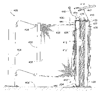
[00100] FIGS. 24 - 26 show a retractable barrier system 400 comprising a
flexible barrier
402 that can selectively extend and retract between a first support member 404
and a second
support member 406. Supports members 404 and 406 are shown mounted to a floor
408;
however, they could also be attached to or combined with an existing column or
wall of a
building. Flexible barrier 402 is schematically illustrated to represent any
structure that can
be wrapped about a roll or drum. Barrier 402, for instance, can be made of a
single sheet of
pliable material or netting or be comprised of one or more straps.
[00101] To assist in wrapping barrier 402 about a rotatable take-up member
410, first
support member 404 includes a coil spring 412 that helps maintain at least
some tension in
barrier 402. When barrier 402 is fully extended between supports members 404
and 406, a
wrench 414 functioning as a manual crank mechanism can be used to further
tighten barrier
402.
[00102] In some example implementations, first support member 404 comprises a
central
pipe 416 and a stationary tube 418 attached to a base plate 420. Take-up
member 410
comprises a rotatable outer tube 422 with an end cap 424 to which the outer
race of a bearing
426 is mounted. The upper end of pipe 416 protrudes upward through a hole in
end cap 424
and also protrudes through the inner race of bearing 426. The inner race of
bearing 426 rests
upon a shoulder 428 on pipe 416 so that take-up member 410 is rotatably
supported by pipe
416.
[00103] A proximal end 430 of barrier 402 is fastened to outer tube 422, and a
distal end or
edge 432 of barrier 402 includes an attachment feature 434 for releasably
connecting to
second support member 406. To help guide barrier 402 onto outer tube 422, a
guide member
436 mounted to the upper end of pipe 416 slidingly engages a bead or upper
edge 438 that
runs along the upper edge of barrier 402.
[00104] To apply a rotational moment on outer tube 422 relative to stationary
tube 418 and
ultimately apply tension to barrier 402, coil spring 412 has one end 439
attached to end cap
424 or outer tube 422, and an opposite end 440 of spring 412 is attached to
base plate 420 or
- 13 -
CA 02778804 2012-05-30
stationary tube 418. As barrier 402 is manually drawn off of outer tube 422,
outer tube 422
rotates, thereby twisting spring 412 and increasing the tension in barrier
402.
[00105] FIG. 24 shows distal edge 432 of barrier 402 being manually pulled
toward second
support member 406. After distal edge 432 is latched onto second support
member 406, a pin
442 protruding downward from wrench 414 is inserted into one of a plurality of
pin holes 444
in end cap 424, and wrench 414 can then be manually rotated as shown in FIG.
25. The
rotation of wrench 414 turns outer tube 422, which tightens barrier 402. Once
barrier 402 is
sufficiently tight, the tension in barrier 402 can be maintained by inserting
a lock pin 446 into
one of pin holes 444 such that lock pin 446 engages the side edge of guide
member 436, thus
limiting the rotation of outer tube 422 and allowing wrench 414 to be removed
and stored
elsewhere, as shown in FIG. 26.
[00106] In a similar barrier system 448, shown in FIGS. 27 ¨ 29, a different
manual crank
mechanism 450 eliminates the need for wrench 414. Mechanism 450 comprises a
lever arm
452 rotatably pinned to pipe 416 and a handle 454 hinged to an outer end 457
of lever arm
452. To tighten barrier 402 after distal edge 432 is latched onto second
support member 406,
lock pin 446 is inserted into one of holes 444, handle 454 is manually pivoted
upward above
the upper edge 438 of barrier 402, and handle 454 and lever arm 452 are
rotated in the
direction of arrow 455 to engage lock pin 446 and rotate outer tube 422,
thereby tightening
barrier 402. Once barrier 402 is sufficiently taut, handle 454 is pivoted back
down where the
face of the tightened barrier 402 can engage the downwardly extending handle
454, as shown
in FIG. 29, thereby preventing outer tube 422 and spring 412 from unwinding.
[00107] In some cases, the span between a barrier's two support members can be
particularly long, which can make winding and unwinding of the barrier
awkward, as the
barrier tends to uncontrollably flop over to one side or the other. Wrapping a
flexible barrier
onto a vertical take-up drum is particularly difficult, as the barrier tends
to "migrate" to the
bottom of the drum. To address this problem, a barrier system 456 shown in
FIGS. 30 ¨ 32,
includes a take-up member 458 with a drum 460 that in addition to rotating
about a first axis
462 can also be rotated about a second axis 464. Second axis 464 allows
barrier 402 to be
deliberately laid over on a preferred side (FIG. 31) as the barrier is being
extended or
retracted. The preferred side might be such that the side facing down, and
perhaps getting
dirty from the floor, is the side of the barrier 402 that is least visible
when barrier 402 is fully
extended and upright (FIG. 30).
- 14 -
CA 02778804 2014-03-28
[00108] Rotation about second axis 464 can be achieved by using a bolt 466 or
some other
appropriate fastener to pivotally mount a drum-supporting frame 468 of take-up
member 458
to a support member 470. A retractable lock pin 472 or some other suitable
device can be
used to help hold frame 468 to its upright and/or laid-over position. Although
axes 462 and
464 are shown perpendicular and intersecting, the two axes do not necessarily
have to be
perpendicular or intersecting.
[00109] After being extended between support members 470 and 406, barrier 402
can be
tightened using a manual crank mechanism 474, as shown in FIG. 32. In this
case, crank
mechanism 474 comprises a crank 476 driving a ratchet 478 and pawl 480
assembly. Crank
476, ratchet 478, and drum 460 can be rotated as a unit about first axis 462
relative to frame
468. In addition to being able to tighten barrier 402 when extended, crank
mechanism 474
can also be used for retracting barrier 402 onto drum 460. In addition or as
an alternative to
crank mechanism 474, drum 460 could be spring-loaded as shown in FIGS. 24 and
27.
[00110] A take-up drum could also be powered by a tubular motor 482 (e.g.,
such as those
produced by SIMU US, Inc.TM of Boca Raton, Florida) as is the case with a
barrier system 484
of FIGS. 33 ¨ 35. A lower stationary portion 482a of motor 482 is fastened to
frame 468,
which in tum is pivotally coupled to support member 470 via bolt 466. An upper
rotating
portion 482b of motor 482 is attached to a rotating drum 480 of a take-up
member 485 so that
portion 482b and drum 480 rotate as a unit about first axis 462 when motor 482
is energized.
Depending on the rotational direction of motor 482, drum 480 either takes in
or pays out a
flexible barrier 486 attached to drum 480.
[00111] To enable a single user to control the actuation of motor 482 while
the user
manually carries a distal end 488 of barrier 486 between support members 470
and 406, the
user has access to a motor controller 490 attached to the barrier's distal end
488. Controller
490 includes one or more switches to command motor 482 to run forward, run in
reverse, or
stop. Communication between controller 490 and motor 482 can be by way of
wires running
along the length of barrier 486 or via a wireless communication link 492
(e.g., radio signals).
[00112] After being extended between support members 406 and 470, barrier 486
can be
tightened using a manual crank mechanism 494, as shown in FIG. 34. In this
case,
mechanism 494 comprises a wrench 496 driving a ratchet 498 and pawl 500
assembly. When
wrench 496 engages a mating nut 502 on ratchet 498, wrench 496, nut 502,
ratchet 498, and
drum 480 can be manually rotated as a unit about first axis 462 relative to
frame 468. Once
- 15 -
CA 02778804 2012-05-30
barrier 486 is tightened, pawl 500 engages ratchet 498 to hold drum 480 in
place, and wrench
496 can be removed, as shown in FIG. 35.
[00113] As an alternative to mounting controller 490 at the distal end of
barrier 486, a
different type of control mechanism 504 can be installed as shown in FIGS. 36
and 37. In
this case, lower stationary portion 482a of motor 482 is pivotally coupled to
a frame 506. An
upper end 508 of a drum 510 is supported by a bearing 512 that can translate
relative to frame
506. Bearing 512 and upper end 508 can move between a stop position (FIG. 36)
and a run
position (FIG. 37). A spring 514 urges bearing 512 and upper end 508 toward
the stop
position where motor 482 is de-energized. Manually tugging on distal end 488
of barrier 486
overcomes spring 514 and forces bearing 512 to the run position of FIG. 37
where bearing
512 engages a limit switch 516 that energizes motor 482. Upon energizing motor
482, drum
510 pays out or draws in barrier 486 depending on the extend-retract-off
position of a selector
switch 518.
[00114] When switch 518 is in the EXTEND-position, manually tugging on distal
end 488
of barrier 486 energizes motor 482 to automatically pay out barrier 486. At
this time, the
user can readily carry distal end 488 of barrier 486 over to second support
member 406.
When the user stops tugging on distal end 486, spring 514 moves bearing 512
away from
limit switch 516 to automatically stop the rotation of drum 510.
[00115] To retract barrier 486, switch 518 is turned to the OFF-position, and
the user tugs
on distal end 488 of barrier 486, thereby forcing bearing 512 against limit
switch 516. This
energizes motor 482 to draw in barrier 486 onto drum 510. While keeping
bearing 512 up
against limit switch 516, the user can readily carry distal end 488 of barrier
486 toward a first
support member 520. When distal end 488 and the user reach first support
member 520, the
user turns switch 518 to its OFF-position so that barrier 486 can be stored in
its retracted
position.
[00116] In another example, shown in FIGS. 38 ¨ 58, a barrier system 600
includes a gear
assembly 602 that facilitates rapidly deploying a flexible barrier 604,
exerting high torque for
tightening barrier 604, maintaining high tension in barrier 604 when in use,
and/or rapidly
retracting barrier 604 for storage. Other optional features include, selective
right-hand/left-
hand configurations (e.g., compare FIGS. 38 and 54), an electric switch 606
that can be added
to indicate whether barrier system 600 is in use, an intermediate coupling 608
(FIG. 55) for
creating an extra long barrier system 610, and removable vehicle-mounted posts
612 (FIGS.
56-58) for certain loading dock applications.
- 16 -
CA 02778804 2012-05-30
[00117] Barrier system 600 comprises a barrier take-up member 614 (drum,
shaft, etc.)
that a set of bearings 616 rotatably supports within a housing 618. A bolt 620
pivotally
connects housing 618 to a first support member 622. One end of barrier 604 is
fastened to
take-up member 614 and an opposite distal end 624 of barrier 604 is suitable
for connection
to a second support member 626. Gear assembly 602 is connected to drive the
rotation of
take-up member 614, as will be explained later in greater detail. Gear
assembly 602 is
connected to take-up member 614, which in turn is coupled to first support
member 622, thus
gear assembly 602 is also coupled to first support member 622.
[00118] In a manner similar to barrier system 456 of FIGS. 30 ¨ 32, take-up
member 614
of barrier system 600 can not only rotate about its longitudinal axis 628
(which is generally
vertical when take-up member 614 is upright) but can also tilt about a
generally horizontal
axis 630. Take-up member 614 rotating about axis 628 either retracts or pays
out barrier 604,
depending on the direction of rotation. Take-up member 614 tilting about axis
630 enables
take-up member 614 to be in a generally upright position (FIG. 39) or in a
laid-over position
(FIG. 41). The upright position can be used for storage or guarding operation,
and the laid-
over position facilitates deploying or retracting barrier 604.
[00119] A sequence of operation might begin with barrier system 600 in its
stored position
of FIGS. 38 and 39. In this position, take-up member 614 is generally upright
with most of
barrier 604 wrapped around it. To help hold this upright position, a latch 632
(e.g., a spring
loaded pin) extends through first support member 622 and protrudes into a hole
in a frame
member 634 of housing 618. With barrier system 600 in its stored position, the
space
between supports members 622 and 626 is generally open and unobstructed by
barrier 604.
[00120] Before extending barrier 604 to block off the area between supports
members 622
and 626, latch 632 is manually retracted, as shown in FIGS. 40 and 41. Bolt
620 and
retracted latch 632 allow housing 618 and take-up member 614 to be tilted
until frame
member 634 engages a stop 636. Stop 636 can be a bar bolted at a select
location on first
support member 622. Take-up member 614 in its laid-over position makes it
easier to extend
and especially retract barrier 604 without barrier 604 tending to crawl or
work its way down
to the lower end of a vertical take-up member.
[00121] To extend barrier 604, as shown in FIGS. 42 and 43, first latch 632 is
inserted in
another hole in frame member 634 to help hold take-up member 614 generally
horizontal.
Gear assembly 602 is then disengaged so that take-up member 614 can spin
freely. This
- 17 -
CA 02778804 2012-05-30
allows barrier 604 to be readily extended by simply tugging on the barrier's
distal end 624
and pulling barrier 604 out from within housing 618.
[00122] Disengaging a gear assembly from a take-up member can be accomplished
in
various ways depending on the particular design of the gear assembly. For the
illustrated
example, gear assembly 602 comprises a drive gear in the form of a worm 638
(similar to a
screw) meshing with a driven gear in the form of a worm gear 640 (similar to a
spur gear),
The gear reduction for this particular example is about 20:1, thus worm gear
640 makes one
revolution for each twenty revolutions of worm 638. Such a high ratio provides
multiple
benefits, which will be explained later. It should be noted that the 20:1 gear
or turning ratio
is only provided as an example, and many other higher or lower ratios would be
likewise
equivalent design choices.
[00123] Worm gear 640 is fastened to take-up member 614 such that the two
rotate as a
unit. Worm 638 is fastened to a shaft 642 that can rotate within a bracket 644
attached to
housing 618. Shaft 642 can also slide axially along its rotational axis 646 so
that worm 638
can be axially moved between an engaged position (FIG. 38) and a disengaged
position
(FIG. 43). A compression spring 648 between bracket 644 and a collar 650 on
shaft 642
urges shaft 642 and worm 638 to the engaged position of FIG. 38. Worm 638 in
the engaged
position places gear assembly 602 in the engaged mode.
[00124] To move worm 638 to the disengaged position of FIG. 43, shaft 642 and
the
attached worm 638 can be manually pushed in direction 652. To assist this
movement, a
manual crank 654 or wrench can be placed on, for example, a hexagon head 656
(FIG. 38) of
shaft 642 and rotated in direction 658 while holding worm gear 640 stationary.
The
interaction between rotating worm 638 and stationary worm gear 640 will force
worm 638
and shaft 642 in direction 652 and compress spring 648 in the process.
[00125] To hold worm 638 is in the disengaged position of FIG. 43, bracket 644
includes a
catch 660, such as a spring-loaded retractable pin. In this example, catch 660
includes a pin
end that under spring force pushes against the outer cylindrical surface of
shaft 642. Shaft
642 has a circumferential groove 662 (FIG. 38) that becomes aligned with the
pin end when
shaft 642 is moved to the position of FIG. 43. When groove 662 and the pin end
of catch 660
are aligned, the pin end, under spring force, drops into groove 662 to hold
shaft 642 in the
extended position of FIG. 43. The movement of the pin end into groove 662 is
represented
by arrow 664 of FIG. 42. It should be noted that catch 660 extends farther out
from bracket
644 in FIG. 39 than in FIG. 42 because in FIG. 42 the pin end of catch 660 has
dropped into
- 18 -
CA 02778804 2012-05-30
groove 662, but in FIG. 39, the pin end is pushing against the major outer
diameter of shaft
642 in a section outside of groove 662.
[00126] With worm 638 disengaged from worm gear 640, as shown in FIG. 43, worm
gear
640 and take-up member 614 can turn freely, thus barrier 604 can be readily
extended by
simply manually gripping the barrier's distal end 624 and pulling barrier 604
out from within
housing 618. A rod 666 at distal end 624 can then be inserted, as shown in
FIGS. 44 and 45,
within two harnesses 668 and 670 that are pivotally attached to second support
member 626.
Although a spring 672 biases harness 670 upward, the weight of the barrier's
distal end 624
pushes harness 670 down to trip electric switch 606. A signal from switch 606
can then be
used for a safety interlock and/or to operate a light or alarm that indicates
the operational
status of barrier system 600.
[00127] At about the same time that distal end 624 is attached to second
support member
626, take-up member 614 can be returned to its upright position of FIGS. 46
and 47. To right
take-up member 614, latch 632 is temporarily retracted.
[00128] Once take-up member 614 is upright, crank 654 can be moved from end
656 of
shaft 642 to a similar hexagonal end 656' that is fixed relative to worm gear
640 and take-up
member 614. Crank 654 can then be rotated in direction 674 to draw in and take
up much of
the slack from barrier 604. Although crank 654 turning worm gear 640 and take-
up member
614 directly (1:1 turning ratio) does not provide the 20:1 mechanical
advantage of gear
assembly 602 operating in an engaged mode, the 1:1 ratio does provide a way of
quickly
taking up most of the slack in barrier 604.
[00129] After much of the slack is taken up, as shown in FIGS. 48 and 49,
catch 660 can
be retracted in the direction of arrow 676 to remove the pin end of catch 660
out from within
groove 662, and at about the same time crank 654 can be turned slightly in
direction 678.
Spring 648 and the slight rotation of worm gear 640 in direction 678 will move
worm 638 in
direction 680 from the worm's disengaged position of FIG. 46 to its engaged
position of FIG.
48.
[00130] To further tighten barrier 604, crank 654 can be moved from worm gear
640 back
onto end 656 to drive worm 638, as shown in FIGS. 50 and 51. With gear
assembly 602 now
in the engaged mode, turning crank 654 in direction 682 turns worm gear 640 in
direction
684 with a high turning ratio (e.g., 20:1). For this example, in the engaged
mode, every
twenty revolutions of crank 654, shaft 642, and worm 638 rotates worm gear 640
and take-up
member 614 one revolution. The high gear ratio provides two benefits. First,
the manual
- 19 -
CA 02778804 2012-05-30
tightening torque applied to crank 654 is greatly multiplied at worm gear 640,
and the
resulting high torque is transmitted to take-up member 614 to produce high
tension in barrier
604. Second, the high gear ratio of a worm drive prevents the tension in
barrier 604 from
backspinning take-up member 614 and worm gear 640, thus the worm drive serves
as a self-
locking mechanism after barrier 604 is tightened. With such a self-locking
mechanism, after
barrier 604 is tightened, crank 654 can be removed from gear assembly 602 and
stored using
a crank holder 686 (FIG. 38) on first support member 622.
[00131] To retract and store barrier 604, a user reverses the steps of FIGS.
44 ¨ 51, thus
the barrier retracting sequence is the reversal of steps illustrated in FIGS.
50 and 51, FIGS. 48
and 49, FIGS. 46 and 47, and FIGS. 44 and 45. Once distal end 624 is separated
from second
support member 626 with worm 638 disengaged, as shown in FIG. 53, crank 654
can be
placed on end 656' to rapidly crank worm gear 640 and take-up member 614 in a
1:1
rotational speed ratio. As an alternative to crank 654, an electric drill with
a hex socket on
end 656' can drive the rotation of worm gear 640 and take-up member 614 to
rapidly retract
barrier 604. As yet another alternative, gear assembly 602 can be moved to the
engaged
mode (worm 638 engaging worm gear 640), and an electric drill with a hex
socket on end 656
can drive the rotation of worm 638 to rapidly retract barrier 604.
[00132] First support member 622 shown in FIG. 54 is the same as first support
member
622 of FIG. 38, only reconfigured. For operating convenience, flexibility and
user
preference, bracket 644 can be selectively mounted at either of two choice
locations 688 or
690. To enable take-up member to be tilted in either direction, stop 636 can
be mounted at a
first location, as shown in FIG. 38 or a second location, as shown in FIG. 54.
In FIG. 54,
crank holder 686 has been omitted to more clearly show the second mounting
location of stop
636.
[00133] To provide an extra long barrier without the need for a fixed central
support post,
the distal ends 624 of two barriers 604 from two separate first support
members 622 can be
joined to each other by way of intermediate coupling 608. In this example,
first support
member 622 on the left side of FIG. 55 is the same as first support member 622
of FIG. 38,
and first support member 622 on the right side of FIG. 55 is configured as
shown in FIG. 54.
Coupling 608 can be any structure that joins two distal ends 624 of two
barriers 604 that are
retractable in generally opposite directions. In the illustrated example,
coupling 608
comprises an upper tube 608a and a lower tube 608b that encircle and capture
the upper and
lower ends of rods 666. An alternative to tubes 608a and 608b would be looped
clips or
- 20 -
CA 02778804 2012-05-30
hooks temporarily or permanently attached to the ends of rods 666, wherein a
clip on one rod
666 could reach over and latch onto an adjacent rod 666.
[00134] Barrier system 600 may be advantageously used for guarding a vehicle
692 such
as an open bed truck or trailer at a pit-style side loading dock 694, as shown
in FIGS. 56 ¨ 58.
In this example, vehicle 692 backs into a pit 696 of dock 694 so that the
floor of vehicle's bed
698 is generally flush with an elevated platform 700 of dock 694. To provide
guarding that
helps prevent someone from accidentally falling into pit 696, the following
method can be
implemented: mounting 702 a first support member 622 to loading dock 694;
mounting 704 a
second support member 626 to loading dock 694 at a location spaced apart from
first support
member 622; installing 706 one or more removable posts 612 to vehicle 692; and
extending
(as shown in FIGS. 57 and 58) retractable, flexible barrier 604 from first
support member 622
to second support member 626 such that barrier 604 engages at least one
removable post 612.
[00135] To temporarily attach post 612 to vehicle 692, the lower end of post
612 can be
sized to fit in any of a series of slots 708 in a conventional bed rail 710 of
vehicle 692. By
installing posts 612 at certain slots 708 and extending barrier 604 along
various routes,
barrier 604 can extend along a length 712 and/or a width 714 of bed 698.
[00136] In some examples, a retractable rollup barrier is provided with
substantial impact
resistance by having the reactive force of the impact transfer directly
between the barrier's
retractable panel and its vertical support members without having to rely on
the strength of
the panel's take-up roller or the strength of the roller's anti-rotation
mechanism.
[00137] In some examples, a retractable rollup barrier includes a stop member
that is
carried by the rollup panel itself
[00138] In some examples, the stop member is an elongate member, such as a
pipe, rod or
bar that broadly distributes an impact reactive force over the height of the
rollup panel.
[00139] In some examples, the stop member comprises multiple separate members
on the
same vertical line. The separate members could be a series of pipes, rods, or
bars that work
together to broadly distribute an impact reactive force over the height of a
retractable panel.
[00140] In some examples, a retractable rollup barrier can be set for various
doorway
widths by simply repositioning a stop member's location on the rollup panel.
[00141] In some examples, the extent to which a rollup panel can extend out
from within a
housing is limited by a thicker section of the panel being unable to fit
through a narrower slot
in one of the barrier's support members.
- 21 -
CA 02778804 2012-05-30
[00142] In some examples, a retractable panel includes reinforcing straps that
greatly
increase the panel's strength.
[00143] In some examples, the reinforcing straps of the retractable panel can
be of a
different color than the rest of the panel so that the panel is clearly
visible when in use.
[00144] In some examples, the panel includes a large warning label that is
visible from a
distance so that people in the area can see that a drop-off hazard exists even
though a closed
dock door may disguise the danger.
[00145] In some examples, the rollup panel does not reach its full extension
from within its
housing until the panel experiences an impact. This feature allows a distal
end of the panel to
be readily hooked or unhooked from an anchored support member without the
panel having
to be pulled tightly against a hard stop to do so.
[00146] In some examples, a retractable barrier straddles a dock leveler.
[00147] In some examples, two anchor support members of a retractable barrier
can serve
as bollard-like members for protecting the lateral edges of a door from
damage.
[00148] In some examples, a distal end of a retractable panel can retract and
stow within a
pocket of a support member housing to protect the distal end from damage and
avoid
interfering with traffic when the retractable barrier is not in use.
[00149] In some examples, a retractable safety barrier comprises a flexible
strap that is
supported by two take-up members, wherein a first take-up member provides
storage for the
strap and a second take-up member provides a way of tightening the strap when
in use.
When the strap receives an impact, the second take-up member reacts more of
the impact
than does the first take-up member, thus the first take-up member can be more
light duty.
[00150] In some examples, a safety barrier system with a flexible strap
includes an
incremental stop mechanism that provides the strap with a plurality of spaced-
apart stopping
points, whereby the strap does not have to rely on friction to resist an
impact.
[00151] In some examples, a safety barrier system includes a first take-up
member for
storing an impactable strap, an incremental stop mechanism for providing the
strap with a
plurality of spaced-apart stopping points, and a second take-up member for
adjusting the
tension in the strap with infinite adjustability.
[00152] In some examples, a safety barrier system includes a take-up member
that tilts 90
degrees to facilitate extending or retracting a flexible barrier.
[00153] In some examples, a flexible barrier includes a power-assist take-up
member that
responds a controller mounted to the distal end of the barrier.
- 22 -
CA 02778804 2012-05-30
[00154] In some examples, a flexible barrier includes a power-assist take-up
member that
is automatically energized by manually tugging on the distal end of a flexible
barrier.
[00155] In some examples, a flexible barrier is tightened first by a spring or
motor and
then further tightened by a manual crank mechanism.
[00156] In some examples, a gear assembly can be selectively configured to
provide: a)
high torque and low rotational speed or b) low torque and high rotational
speed.
[00157] In some examples, a gear assembly for retracting a flexible barrier
can be
disengaged to facilitate rapid deployment of the barrier.
[00158] In some examples, a common crank can be used to selectively engage and
drive
two different gears of a gear assembly.
[00159] In some examples, the gear assembly and a tilt-stop can be selectively
installed at
choice locations for right-hand or left-hand use.
[00160] In some examples, the gear assembly for cranking a barrier take-up
member is a
worm drive that also serves as an anti-rotation mechanism that prevents
tension in the barrier
from driving the take-up member in reverse.
[00161] In some examples, the barrier system includes an intermediate support
post that
can be temporarily installed on the open flat bed of a truck or trailer so
that the barrier can
extend from a stationary point on the loading dock over to the vehicle.
[00162] Although certain example methods, apparatus and articles of
manufacture have
been described herein, the scope of coverage of this patent is not limited
thereto. On the
contrary, this patent covers all methods, apparatus and articles of
manufacture fairly falling
within the scope of the appended claims either literally or under the doctrine
of equivalents.
- 23 -