Note: Descriptions are shown in the official language in which they were submitted.
CA 02778892 2012-04-25
1
DESCRIPTION
FLOAT DEVICE
Technical Field
The present invention relates to a float device
such as ocean observation float device, which is called
a "profiling float" used for an ocean monitoring system
(which will be called Argo program below), and
particularly to a technique capable of reducing the
number of parts and adjusting a buoyant force with high
accuracy.
Background Art
In order to address the environmental problems
such as global warming, it is necessary to reveal
environmental variation mechanisms in the global
environment and to determine the total amount and the
- circulation of greenhouse gas. The Argo program is
being promoted in order to address the problems. Under
the Argo program a cylinder-shaped ocean observation
float device having a length of 1 m which is called a
"profiling float" is deployed from a ship, then
automatically descends up to a depth (about 2000 m) in
=
balance with a preset density of around water, and
drifts for several days. When the power supply is
turned on by an internal timer, the ocean observation
float device comprising a float hull having a certain
CA 02778892 2012-04-25
2
buoyancy is raised by a buoyant force adjustment
mechanism.
The ocean observation float device is ascending
while measuring water temperature and salinity. The
ocean observation float device floating on the sea
surface is powered off after transmitting the
. observation data from the sea surface via satellites,
and is caused to descend by the buoyant force
adjustment mechanism. The operation is repeated for
several years.
The above buoyant force adjustment mechanism is
configured as follows, for example. That is, FIG. 4 is
an explanatory diagram schematically showing a buoyant
force adjustment mechanism 100 for adjusting a buoyant
force of an ocean observation float device by carrying
hydraulic oil between an external buoyant force
adjustment bladder and an internal oil reservoir. The
buoyant force adjustment mechanism 100 comprises an
internal oil reservoir 110 for storing hydraulic oil
therein, a plunger 120 and an external buoyant force
adjustment bladder 130, which are connected via oil
pipes 140, 141 and 142. The oil pipes 140, 141 and 142
are provided with a check valve 150, a check valve 151
and a valve 152, respectively.
In the buoyant force adjustment mechanism 100,
when the hydraulic oil is carried from the internal oil
reservoir 110 to the external buoyant force adjustment
= CA 02778892 2012-04-25
3
bladder 130, the plunger 120 is moved in the arrow a
direction in FIG. 4 while the valve 152 is closed, and
the hydraulic oil is taken from the internal oil
reservoir 110 into the plunger 120. At this time, the
hydraulic oil cannot be sucked from the external
buoyant force adjustment bladder 130 by the operation
of the check valve 151. Then, the plunger 120 is moved
in the arrow p direction in FIG. 4 and the hydraulic
oil is supplied from the plunger 120 to the external
buoyant force adjustment bladder 130. At this time,
the hydraulic oil does not return to the internal oil
reservoir 110 because of the operation of the check
valve 150. When the external buoyant force adjustment
bladder 130 swells in this way, the ocean observation
float device ascends.
On the other hand, when the ocean observation
float device descends, the hydraulic oil is returned
from the external buoyant force adjustment bladder 130
to the internal oil reservoir 110. In this case, the
valve 152 is opened so that the hydraulic oil is
returned to the internal oil reservoir 110 by a
contraction force of the external buoyant force
adjustment bladder 130.
Disclosure of Invention
The above buoyant force adjustment mechanism has
the following problems. That is, three valves are
required, and thus the number of parts increases and
CA 02778892 2012-04-25
4
the float hull can be increased in its size. The
buoyant force adjustment mechanism can be controlled by
the plunger during the ascent but cannot be controlled
by the plunger during the descent, and thus there is a
problem that the buoyant force is difficult to be
.controlled with high accuracy.
It is therefore an object of the present invention
to provide a float device capable of reducing the
number of parts and controlling a buoyant force with
high accuracy during both ascent and descent.
The float device according to the present
invention is configured as follows in order to meet the
object.
A float device is characterized in that the float
device comprises a float hull having a certain
buoyancy, a drive motor provided inside the float hull,
a plunger reciprocating along with rotation of the
drive motor, an internal oil reservoir for housing
hydraulic oil therein, an externally-opened cylinder
attached to the float hull, a buoyant force adjustment
piston reciprocating in the cylinder along with
exit/entry of the hydraulic oil, and a three-way valve
having a first connection port connected to the
plunger, a second connection port connected to the
internal oil reservoir and a third connection port
connected to the cylinder, for switching the flow
between the first connection port and the second
CA 02778892 2012-04-25
connection port and the flow between the first
connection port and the third connection port.
A float device is characterized in that the float
device comprises a float hull having a certain
buoyancy, a drive motor provided inside the float hull,
a plunger reciprocating along with rotation of the
drive motor, an internal oil reservoir for housing an
hydraulic oil therein, an externally-opened cylinder
attached to the float hull, a buoyant force adjustment
piston reciprocating in the cylinder along with
exit/entry of the hydraulic oil, a branch pipe
connected at the branch point to the plunger, a first
two-way valve attached to one side of the branch pipe
and connected to the internal oil reservoir, and a
second two-way valve attached to the other side of the
branch pipe and connected to the cylinder.
Brief Description of Drawings
FIG. 1 is a longitudinal cross section view
showing an ocean observation float device according to
one embodiment of the present invention;
FIG. 2 is an explanatory diagram schematically
showing a buoyant force adjustment mechanism
incorporated in the ocean observation float device;
FIG. 3 is an explanatory diagram schematically
showing a variant of the buoyant force adjustment
mechanism; and
FIG. 4 is an explanatory diagram schematically
CA 02778892 2012-04-25
6
showing an example of buoyant force adjustment
mechanism.
Best Mode for Carrying Out the Invention
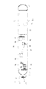
FIG. 1 is a diagram showing an ocean observation
float device 10 according to one embodiment of the
present invention, and FIG. 2 is an explanatory diagram
schematically showing a buoyant force adjustment
mechanism 30 incorporated in the ocean observation
float device 10.
The ocean observation float device 10 comprises a
float hull 11 formed in a cylinder-like shape. The
float hull 11 is provided with a hollow or the like
inside or outside, and is set to have a predetermined
buoyant force. An electronic part mounting unit 20
mounting an antenna for transmission and reception with
external communication devices, and various ocean
observation electronic devices thereon is mounted on a
top part 12 of the float hull 11. Part of the buoyant
force adjustment mechanism 30 is mounted on a bottom
part 13 of the float hull 11.
The buoyant force adjustment mechanism 30
comprises a plunger mechanism 40 arranged inside the
float hull 11, an internal oil reservoir 50 for storing
an hydraulic oil therein, a three-way valve mechanism
60, a buoyant force adjustment mechanism 70 provided
outside the float hull 11, and a control unit 35 for =
controlling them in an associated manner. An oil pipe
CA 02778892 2012-04-25
7
80, an oil pipe 81, and an oil pipe 82 connect between
the plunger mechanism 40 and the three-way valve
mechanism 60, between the internal oil reservoir 50 and
the three-way valve mechanism 60, and between the
buoyant force adjustment unit 70 and the three-way
valve mechanism 60, respectively.
The plunger mechanism 40 comprises a drive motor
41, a deceleration mechanism 42 for transmitting a
rotation force of the drive motor 41 while
decelerating, a gear unit 43 for transforming the
rotation force transmitted by the deceleration
mechanism 42 into a reciprocating power, and a plunger
44 reciprocating by the gear unit 43.
The three-way valve mechanism 60 comprises a
three-way valve 61, and an operation motor 62 for
operating the three-way valve 61. The three-way valve
61 has a first connection port 61a connected to the
plunger 44, a second connection port 61b connected to
the internal oil reservoir 50, and a third connection
port 61c connected to a cylinder 71 described later,
and switches the flow between the first connection port
61a and the second connection port 61b and the flow
between the first connection port 61a and the third
connection port 61c.
The buoyant force adjustment unit 70 comprises an
externally-opened cylinder (variable volume body) 71,
and a buoyant force adjustment piston 72 reciprocating
CA 02778892 2012-04-25
8
in the cylinder 71 along with exit/entry of the
hydraulic oil.
The plunger mechanism 40 and the three-way valve
mechanism 60 are controlled such that an associated
operation is performed as follows. That is, the three-
way valve 61 is switched to cause the first connection
=
port 61a and the second connection port 61b to permit
flow during the movement of the plunger 44 to one side,
and the three-way valve 61 is switched to cause the
first connection port 61a and the third connection port
61c to permit flow during the movement of the plunger
44 to the other side, thereby carrying the hydraulic
oil between the internal oil reservoir 50 and the
cylinder 71.
With the thus-configured ocean observation float
device 10, a buoyant force is adjusted as follows.
That is, the hydraulic oil is carried from the internal
oil reservoir 50 to the cylinder 71 during the ascent.
At first, the drive motor 41 is operated to move the
plunger 44 in the X-direction in FIG. 2. At this time,
the three-way valve 61 is switched to cause the first
connection port 61a and the second connection port 61b
to permit flow. Accordingly, the hydraulic oil is
carried from the internal oil reservoir 50 to the
plunger 44. Subsequently, the drive motor 41 is
operated to move the plunger 44 in the Y-direction in
FIG. 2. At this time, the three-way valve 61 is
CA 02778892 2012-04-25
9
switched to cause the first connection port 61a and the
third connection port 61c to permit flow. Accordingly,
the hydraulic oil is carried from the plunger 44 to the
cylinder 71 and the buoyant force adjustment piston 72
moves outward.
Accordingly, a buoyant force increases and the
float hull 11 slightly ascends. The same operations
are repeated so that the amount of hydraulic oil inside
the cylinder 71 increases and the float hull 11 ascends
to a predetermined position.
On the other hand, during the descent, the
hydraulic oil is carried from the cylinder 71 to the
internal oil reservoir 50. At first, the drive motor
41 is operated to move the plunger 44 in the X-
direction in FIG. 2. At this time, the three-way valve
61 is switched to cause the first connection port 61a
and the third connection port 61c to permit flow.
Accordingly, the hydraulic oil is carried from the
cylinder 71 to the plunger 44 and the buoyant force
adjustment piston 72 moves inward. Accordingly, the
buoyant force decreases. Subsequently, the drive motor
41 is operated to move the plunger 44 in the Y-
direction in FIG. 2. At this time, the three-way valve
61 is switched to cause the first connection port 61a
and the second connection port 61b to permit flow.
Accordingly, the hydraulic oil is carried from the
plunger 44 to the internal oil reservoir 50.
CA 02778892 2012-04-25
The same operations are repeated so that the
amount of hydraulic oil inside the cylinder 71
decreases and the float hull 11 descends to a
predetermined position.
5 With the ocean observation float device 10
according to the present embodiment, the transport of
the hydraulic oil can be controlled only by the three-
way valve 61, and thus the number of parts can be
reduced and the float hull can be downsized. The float
10 device can be controlled by the plunger 44 during both
the ascent and the descent, and thus the buoyant force
can be controlled with high accuracy, thereby
positioning the float hull 11 at a desired position.
Thus, the ocean data can be measured with high
accuracy.
The position of the cylinder 71 is measured by an
encoder 45 and the position of the plunger 44 is
measured by an encoder 46 with high accuracy, and the
positions may be input into the control unit 35 to be
used as positioning information and buoyant force
adjustment information. A potentiometer may be used
instead of the encoder 45.
A bellows type bag or the like may be used as a
variable volume body instead of the cylinder 71.
A working robot may be attached to the float hull
11 and may be used as an undersea robot.
FIG. 3 is an explanatory diagram schematically
CA 02778892 2012-04-25
11
showing a structure of a buoyant force adjustment
mechanism 30A according to a variant of the buoyant
force adjustment mechanism 30. In FIG. 3, like
reference numerals are denoted to the same parts as
those in FIG. 2, and a detailed explanation thereof
will be omitted.
In the present variant, a two-way valve mechanism
90 is provided instead of the three-way valve mechanism
60. The two-way valve mechanism 90 comprises a branch
pipe 91 connected at the branch point to the plunger
44, a first two-way valve 92 attached to one side of
the branch pipe 91 and connected to the internal oil
reservoir 50, a second two-way valve 93 attached to the
other side of the branch pipe 91 and connected to the
cylinder 71, and an operation motor 94 for opening and
closing the first two-way valve 92 and the second two-
way valve 93.
The plunger mechanism 40 and the two-way valve
mechanism 90 are controlled to perform an associated
operation as follows. That is, the first two-way valve
92 is Opened and the second two-way valve 93 is closed
during the movement of the plunger 44 to one side and
the first two-way valve 92 is closed and the second
two-way valve 93 is opened during the movement of the
= 25 plunger 44 to the other side, thereby transporting the
hydraulic oil between the internal oil reservoir 50 and
the cylinder 71 via the plunger 44.
CA 02778892 2012-04-25
12
With the thus-configured buoyant force adjustment
mechanism 30A, a buoyant force is adjusted as follows.
That is, the hydraulic oil is carried from the internal
oil reservoir 50 to the cylinder 71 during the ascent.
At first, the drive motor 41 is operated to move the
plunger 44 in the X-direction in FIG. 3. At this time,
the first two-way valve 92 is opened and the second
two-way valve 93 is closed so that the hydraulic oil is .
carried from the internal oil reservoir 50 to the
plunger 44. Subsequently, the drive motor 41 is
operated to move the plunger 44 in the Y-direction in
FIG. 3. At this time, the first two-way valve 92 is
closed and the second two-way valve 93 is opened so
that the hydraulic oil is carried from the plunger 44
to the cylinder 71 and the buoyant force adjustment
piston 72 moves outward. In this way, the hydraulic
oil is carried between the internal oil reservoir 50
and the cylinder 71 via the plunger 44.
Accordingly, a buoyant force increases and the
float hull 11 slightly ascends. The same operations
are repeated so that the amount of hydraulic oil inside
the cylinder 71 increases and the float hull 11 ascends
to a predetermined position.
On the other hand, during the descent, the
hydraulic oil is carried from the cylinder 71 to the
internal oil reservoir 50. At first, the drive motor
41 is operated to move the plunger 44 in the
= = CA 02778892 2012-04-25
13
X-direction in FIG. 3. At this time, the first two-way
valve 92 is closed and the second two-way valve 93 is
opened so that the hydraulic oil is carried from the
cylinder 71 to the plunger 44 and the buoyant force
adjustment piston 72 moves inward. Accordingly, a
buoyant force decreases. Subsequently, the drive motor
41 is operated to move ,the plunger 44 in the Y-
. direction in FIG. 3. At this time, the first two-way
valve 92 is opened and the second two-way valve 93 is
closed so that the hydraulic oil is carried from the
plunger 44 to the internal oil reservoir 50.
The same operations are repeated so that the
amount of hydraulic oil inside the cylinder 71
decreases and the float hull 11 descends to a
predetermined position.
Also with the buoyant force adjustment mechanism
30A according to the present variant, a buoyant force
can be adjusted similarly to the buoyant force
adjustment mechanism 30 and thus similar effects can be
obtained.
The present invention is not limited to the
embodiment. For example, the ocean observation float
device has been described in the above example, but any
float devices for adjusting a buoyant force of the
float hull may be applied to other use, not limited to
measurement. Additionally, the embodiment can be
variously modified without departing from the spirit of
CA 02778892 2012-04-25
14
the present invention.
Industrial Applicability
According to the present invention, it is possible
to provide a float device capable of reducing the
number of parts and controlling a buoyant force with
high accuracy during both ascent and descent.