Note: Descriptions are shown in the official language in which they were submitted.
CA 2779219 2017-03-22
SPECIFICATION
ELECTRIC MOTOR AND/OR GENERATOR WITH
MECHANICALLY TUNEABLE PERMANENT MAGNETIC FIELD
[0001] The present application claims the priority of US Patent Application
Serial No.
12/610,271 filed October 30, 2009, and of US Patent Application Serial No.
12/905,834
filed October 15, 2010.
Technical Field
[0002] The present invention relates to electric motors and generators and in
particular to
adjusting the orientation of fixed magnets and/or non-magnetically conducting
shunting
piece in a rotor to obtain efficient operation at various RPM.
Background Art
[0003] Brushless DC motors are often required to operate at various RPM but
can only
achieve efficient operation over a limited RPM range. Further, generators and
alternators
are often required to operate over a broad RPM range. For example, automotive
alternators operate at an RPM proportional to engine RPM and windmill
alternators
operate at an RPM proportional to wind speed. Unfortunately, known alternators
generate
electricity at a voltage proportion to RPM.
Because RPM cannot be easily controlled, other elements are often required to
adjust the
output voltage, adding inefficiency, complexity, and cost to the alternator
systems.
[0004] Some designs have attempted to broaden RPM range using "field
weakening'' to
allow the motor to be efficient at very low RPM, and still obtain efficient
higher RPM
operation. Such field weakening can be applied to Interior Permanent Magnet
Synchronous Motors (IPMSM) or AC synchronous induction motors, allowing three
to four
times base speed (RPM) with reasonable efficiency. Unfortunately, field
weakening with
conventional methods can sacrifice efficiency at higher RPM and increases the
complexity of controller algorithms and software.
[0005] In a generator/alternator application, the output voltage is
proportional to magnetic
flux strength requiring an inverter or separate electromagnetic exciter coil
in automotive
alternators that are only 60-70 percent efficient because of the very wide RPM
range the
alternators must operate
- 1 -
CA 02779219 2012-04-27
WO 2011/053472 PCT/US2010/052978
over. Similar issues are present in wind power generation where variations in
wind speed
encountered resulting in operating inefficiencies.
Disclosure of the Invention
[0006] The present invention addresses the above and other needs by providing
apparatus and
method for tuning the magnetic field of brushless motors and alternators to
obtain efficient
operation over a broad RPM range. The motor or alternator includes fixed
windings (or stator)
around a rotating rotor carrying permanent magnets. The permanent magnets are
generally
cylindrical and have North (N) and South (S) poles formed longitudinally in
the magnets.
Magnetically conducting circuits are formed by the magnets residing in
magnetic conducting pole
pieces (for example, low carbon or soft steel, and/or laminated insulated
layers, of non-
magnetizable material). Rotating the permanent magnets, or rotating non-
magnetically conducting
shunting pieces, inside the pole pieces, either strengthens or weakens the
resulting magnetic field to
adjust the motor or alternator for low RPM torque or for efficient high RPM
efficiency. Varying
the rotor magnetic field adjusts the voltage output of the alternators
allowing, for example, a
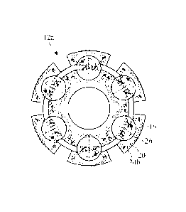
windmill generator, to maintain a fixed voltage output. Other material used in
the rotor is
generally non-magnetic, for example, stainless steel.
100071 In accordance with one aspect of the present invention, there are
provided apparatus and
methods to vary the flux strength of rotor,/armature in an electric motor to
provide improved starting
torque and high RPM efficiency.
[0008] In accordance with another aspect of the present invention, there are
provided apparatus and
methods to vary the magnetic flux strength of rotor/armature in
generator/alternator applications to
control output voltage independent of RPM. Many known alternator applications
cannot control
alternator RPM, for example, automotive alternators which must operate at an
RPM proportional to
engine RPM and wind power generation which are subject to wind speed. Varying
the magnetic
flux strength of rotor/armature allows output voltage to be controlled
independently of RPM
thereby eliminating the need for an inverter or separate electromagnetic
exciter coil.
[0009] In accordance with yet another aspect of the present invention, there
are provided
apparatus and methods to vary the magnetic field of a motor or generator by
rotating half length
cylindrical permanent magnets to align or miss-align the rotatable magnets
with fixed half length
permanent magnets.
- 2 -
CA 02779219 2012-04-27
WO 2011/053472 PCT/US2010/052978
100101 In accordance with another aspect of the present invention, there are
provided apparatus and
methods to vary the magnetic field of a motor or generator by rotating
magnetic shunting pieces in
cooperation with fixed permanent magnets.
[0011] In accordance with still another aspect of the present invention, there
are provided
apparatus and methods adaptable to vary the magnetic field of a motor suitable
for application to an
induction motor to provide a weak magnetic field for starting the motor in an
asynchronous mode
and to provide a strong magnetic field for efficient operation in a
synchronous mode.
Brief Description of the Drawing
[0012] The above and other aspects, features and advantages of the present
invention will be more
apparent from the following more particular description thereof, presented in
conjunction with the
following drawings wherein:
[0013] FIG. IA is a side view of a reconfigurable electric motor according to
the present invention.
[0014] FIG. 1B is an end view of the reconfigurable electric motor according
to the present
invention.
[0015] FIG. 2 is a cross-sectional view of the reconfigurable electric motor
according to the
present invention taken along line 2-2 of FIG. 1A.
[0016] FIG. 3 is a perspective view of a cylindrical two pole permanent magnet
according to the
present invention.
[0017] FIG. 4 is a perspective view of a cylindrical four pole permanent
magnet according to the
present invention.
100181 FIG. 5A is a side view of a tunable permanent magnet rotor according to
the present
invention, in a radially aligned configuration.
[0019] FIG. 5B is an end view of the tunable permanent magnet rotor according
to the present
invention, in the radially aligned configuration.
[0020] FIG. 6A is an end view of a tunable permanent magnet rotor according to
the present
invention, in the radially aligned configuration, with the permanent two pole
magnets aligned for a
maximum (or strong) magnetic field.
[0021] FIG. 6B is an end view of a tunable permanent magnet rotor according to
the present
invention, in a radially aligned configuration, with the permanent two pole
magnets aligned for a
medium magnetic field.
- 3 -
CA 02779219 2012-04-27
WO 2011/053472 PCT/US2010/052978
[0022] FIG. 6C is an end view of a tunable permanent magnet rotor according to
the present
invention, in the radially aligned configuration, with the permanent two pole
magnets aligned for a
minimum (or weak) magnetic field.
[0023] FIG. 7A shows the strong magnetic field corresponding to FIG. 6A.
[0024] FIG. 7B shows the weak magnetic field corresponding to FIG. 6C.
[0025] FIG. 8 is a side view of a tunable pernianent magnet rotor according to
the present
invention, in a flux squeeze configuration.
[0026] FIG. 9 is an end view of the tunable permanent magnet rotor according
to the present
invention, in the flux squeeze configuration.
[0027] FIG. 10A is an end view of a tunable permanent magnet rotor according
to the present
invention, in the flux squeeze configuration, with the permanent two pole
magnets aligned for a
maximum (or strong) magnetic field.
[0028] FIG. 10B is an end view of a tunable permanent magnet rotor according
to the present
invention, in a flux squeeze configuration, with the permanent two pole
magnets aligned for a
medium magnetic field.
[0029] FIG. 10C is an end view of a tunable permanent magnet rotor according
to the present
invention, in the flux squeeze configuration, with the permanent two pole
magnets aligned for a
minimum (or weak) magnetic field.
[0030] FIG. 11A shows the strong magnetic field corresponding to FIG. 10A.
[0031] FIG. 11B shows the weak magnetic field corresponding to FIG. 10C.
[0032] FIG. 12 is an end view of a tunable permanent magnet rotor according to
the present
invention, having pairs of the cylindrical two pole permanent magnets in the
radially aligned
configuration.
[0033] FIG. 13 is an end view of a tunable permanent magnet rotor according to
the present
invention, having pairs of the cylindrical two pole permanent magnets in the
flux squeeze
configuration.
[0034] FIG. 14 is an end view of a hybrid tunable permanent internal magnet
and fixed external
magnet rotor, in the radially aligned configuration, with the internal magnets
aligned for maximum
flux, according to the present invention.
[0035] FIG. 15A is an end view of the hybrid tunable permanent internal magnet
and fixed external
magnet rotor, in the radially aligned configuration, tuned for a maximum
magnetic field according
to the present invention.
- 4 -
CA 02779219 2012-04-27
WO 2011/053472 PCT/US2010/052978
[0036] FIG. 15B is an end view of the hybrid tunable permanent internal magnet
and fixed external
magnet rotor, in the radially aligned configuration, tuned for a minimum
magnetic field according
to the present invention.
[0037] FIG. 16 is an end view of a hybrid tunable permanent internal magnet
and fixed external
magnet rotor, in the flux squeeze configuration, according to the present
invention.
[0038] FIG. 17A is an end view of the hybrid tunable permanent internal magnet
and fixed external
magnet rotor, in the flux squeeze configuration, tuned for a maximum magnetic
field according to
the present invention.
100391 FIG. 17B is an end view of the hybrid tunable permanent internal magnet
and fixed external
magnet rotor, in the flux squeeze configuration, tuned for a minimum magnetic
field according to
the present invention.
[0040] FIG. 18 is an end view of an element for constructing a laminated pole
piece according to
the present invention.
[0041] FIG. 18A is a detail 18A of FIG. 18.
[0042] FIG. 19A is a side view of a first embodiment of apparatus for
adjusting the cylindrical two
pole permanent magnets in a first magnet position.
[0043] FIG. 19B is an end view of the first embodiment of apparatus for
adjusting the cylindrical
two pole permanent magnets in the first magnet position.
[0044] FIG. 20A is a side view of the first embodiment of apparatus for
adjusting the cylindrical
two pole permanent magnets in a second magnet position.
[0045] FIG. 20B is an end view of the first embodiment of apparatus for
adjusting the cylindrical
two pole permanent magnets in the second magnet position.
[0046] FIG. 21A is a side view of a second embodiment of apparatus for
adjusting the cylindrical
two pole permanent magnets in a first magnet position.
[0047] FIG. 21B is an end view of the second embodiment of apparatus for
adjusting the
cylindrical two pole permanent magnets in the first magnet position.
[0048] FIG. 22A is a side view of the second embodiment of apparatus for
adjusting the
cylindrical two pole permanent magnets in a second magnet position.
[0049] FIG. 22B is an end view of the second embodiment of apparatus for
adjusting the
cylindrical two pole permanent magnets in the second magnet position.
[0050] FIG. 23A is a side view of a third embodiment of apparatus for
adjusting the cylindrical
two pole permanent magnets in a first magnet position.
- 5 -
CA 02779219 2012-04-27
WO 2011/053472 PCT/US2010/052978
[0051] FIG. 23B is an end view of the third embodiment of apparatus for
adjusting the cylindrical
two pole permanent magnets in the first magnet position.
[0052] FIG. 24A is a side view of the third embodiment of apparatus for
adjusting the cylindrical
two pole permanent magnets in a second magnet position.
[0053] FIG. 24B is an end view of the third embodiment of apparatus for
adjusting the cylindrical
two pole permanent magnets in the second magnet position.
[0054] FIG. 25A is an alternative gear apparatus for adjusting the positions
of the cylindrical two
pole internal permanent magnets of the hybrid tunable permanent internal
magnet and fixed
external magnet rotor, in the radially aligned configuration, according to the
present invention.
[0055] FIG. 25B is an alternative gear apparatus for adjusting the positions
of the cylindrical two
pole internal permanent magnets of the hybrid tunable permanent internal
magnet and fixed
external magnet rotor, in the flux squeeze configuration, according to the
present invention.
[0056] FIG. 26A is a side view of a biasing system for controlling magnet
positions for a motor
according to the present invention.
[0057] FIG. 26B is an end view of the biasing system for controlling magnet
positions for a motor
according to the present invention.
[0058] FIG. 27A is a side view of a biasing system for controlling magnet
positions for a generator
according to the present invention.
[0059] FIG. 27B is an end view of the biasing system for controlling magnet
positions for a
generator according to the present invention.
[0060] FIG. 28A is a side view of a tunable permanent magnet rotor according
to the present
invention having rotatable half length cylindrical magnets and co-axial fixed
half length cylindrical
magnets and a biasing system for controlling magnet positions.
[0061] FIG. 28B is a front view of a tunable permanent magnet rotor according
to the present
invention having rotatable half length cylindrical magnets and co-axial fixed
half length cylindrical
magnets and the biasing system for controlling magnet positions taken along
line 28B-28B of FIG.
28A.
100621 FIG. 29A is a side view of a rotor having rotatable half length
cylindrical magnets and co-
axial fixed half length cylindrical magnets and a biasing system for
controlling magnet positions.
[0063] FIG. 29B is a front view of the rotor having rotatable half length
cylindrical magnets and
co-axial fixed half length cylindrical magnets and the biasing system for
controlling magnet
positions.
- 6 -
CA 2779219 2017-03-22
[0064] FIG. 30A is an end view of a tunable permanent magnet rotor according
to the present
invention, having moveable magnetic shunting pieces aligned to provide a
strong magnetic field.
[0065] FIG. 30B is an end view of the tunable permanent magnet rotor according
to thc present
invention, having the moveable magnetic shunting pieces misaligned to provide
a weak magnetic
field.
[0066] FIG. 31A is an end view of the tunable permanent magnet rotor according
to the present
invention, showing the strong magnetic field obtained by having the moveable
magnetic shunting
pieces aligned.
[0067] FIG. 3IB is an end view of the tunable permanent magnet rotor according
to the present
invention, showing the weak magnetic field obtained by having thc moveable
magnetic shunting
pieces misaligned.
[0068] Corresponding reference characters indicate corresponding components
throughout the
several views of the drawings.
Best Mode for Carrying out the Invention
[0069] The following description is of the best mode presently contemplated
for carrying out the
invention. This description is not to be taken in a limiting sense, but is
made merely for the purpose
of describing one or more preferred embodiments of the invention.
[0070] A side view of a reconfigurable electric motor 10 according to the
present invention is shown
in FIG. 1A, an end view of the reconfigurable electric motor 10 is shown in
FIG. IB, and a cross-
sectional view of the reconfigurable electric motor 10 taken along line 2-2 of
FIG. 1A is shown in
FIG. 2. The motor 10 includes stator windings 14 and a rotor 12 residing
inside the stator windings
14. The motor 10 is a brushless AC inductive motor including a magnetic
circuit including at least
one permanent magnet 16 (see FIGS. 3-7) or moveable magnetic shunting pieces
80 (see FIGS. 30A-
31B) in the rotor 12, which magnets 16 or magnetic shunting pieces 80 may be
adjusted to cOntrol
the rotor's magnetic field over a range of RPM for efficient operation.
[0071] A perspective view of a cylindrical two pole permanent magnet 16
according to the present
invention is shown in FIG. 3 and a perspective view of a cylindrical four pole
permanent magnet 16a
according to the present invention is shown in FIG. 4. The poles of the magnet
16 and 16a run the
lengths of thc magnets as indicated by dashed lines.
[0072] A side view of a tunable permanent magnet rotor 12a according to the
present invention, in a
radially aligned configuration, is shown in FIG. 5A and an end view of the
tunable permanent
- 7 -
CA 02779219 2012-04-27
WO 2011/053472 PCT/US2010/052978
magnet rotor 12a, in the radially aligned configuration, is shown in FIG. 5B.
The rotor 12a includes
the magnets 16, an inner pole piece 18, outer pole pieces 20, and non-magnetic
spacer 22. The pole
pieces are a magnetically conducting but non-magnetizable material which
conduct the magnetic
field of the magnet 16 to create a rotor magnetic field. The spacer 22
separates the inner pole piece
18 from the outer pole pieces 20 and air gaps 23 separate the outer pole
pieces 20. The magnets 16
are generally cylindrical and parallel axial with a motor shaft 11, although
other shapes of magnets
might be used.
[0073] An end view of a tunable permanent magnet rotor 12a, with the permanent
two pole
magnets 16 aligned for a maximum (or strong) magnetic field 24a (see FIG. 7A)
is shown in FIG.
6A, an end view of a tunable permanent magnet rotor 12a with the permanent two
pole magnets 16
aligned for a medium magnetic field is shown in FIG. 6B, and an end view of a
tunable permanent
magnet rotor 12a, with the permanent two pole magnets 16 aligned for a minimum
(or weak)
magnetic field 24b (see FIG. 7B) is shown in FIG. 6C. In an electric motor,
the alignment
providing a strong magnetic field provides hi torque at low RPM and the
alignment providing a
weak magnetic field provides efficient operation at high RPM. In a generator,
the output voltage
may be adjusted by adjusting the magnet alignment allowing constant voltage in
generators having
varying RPM, such as automotive alternators and wind power generators.
100741 The strong magnetic field 24a corresponding to FIG. 6A is shown in FIG.
7A and the weak
magnetic field corresponding to FIG. 6C is shown in FIG. 7B.
[0075] A side view of a tunable permanent magnet rotor 12b according to the
present invention, in
a flux squeeze configuration, is shown in FIG. 8 and an end view of the
tunable permanent magnet
rotor 12b shown in FIG. 9. The rotor 12b includes the magnets 16, pole pieces
21, and air gaps 23.
The pole pieces are a tnagnetically conducting but non-magnetizable tnaterial
which conduct the
magnetic field of the magnet 16 to create a rotor magnetic field. The air gaps
23 separate the pole
pieces 21.
[0076] An end view of a tunable permanent magnet rotor 12b, with the permanent
two pole
magnets 16 aligned for a maximum (or strong) magnetic field 24a' (see FIG.
11A) is shown in FIG.
10A, an end view of a tunable permanent magnet rotor 12b with the permanent
two pole magnets
16 aligned for a medium magnetic field is shown in FIG. 10B, and an end view
of a tunable
permanent magnet rotor 12b, with the permanent two pole magnets 16 aligned for
a minimum (or
weak) magnetic field 24b' (see FIG. 11B) is shown in FIG. 10C. In an electric
motor, the
alignment providing a strong magnetic field provides hi torque at low RPM and
the alignment
providing a weak magnetic field provides efficient operation at high RPM. In a
generator, the
- 8 -
CA 2779219 2017-03-22
output voltage may be adjusted by adjusting the magnet alignment allowing
constant voltage in
generators having varying RPM, such as automotive alternators and wind power
generators.
[0077] The strong magnetic field 24a' corresponding to FIG. 10A is shown in
FIG. 11A and the weak
magnetic field corresponding to FIG. IOC is shown in FIG. 1 IB.
[0078] An end view of a tunable permanent magnet rotor 12c according to the
present invention,
having pairs of the cylindrical two pole permanent magnets 16 in the radially
aligned configuration is
shown in FIG. 12 and an end view of a tunable permanent magnet rotor 12d
according to the present
invention, having pairs of the cylindrical two pole permanent magnets 16 in
the flux squeeze
configuration is shown in FIG. 13. The present invention is not limited to
single or pairs of magnets,
and any number of magnets may be grouped as appropriate for the application.
For example, three,
four, five, or more magnets may replace the pairs of magnets in FIGS. 12 and
13.
[0079] An end view of a hybrid rotor 12a' including tunable permanent internal
magnets 16 and fixed
external magnets 17, in the radially aligned configuration, according to thc
present invention, is
shown in FIG. 14. The combination of the tunable permanent internal magnets 16
and fixed external
magnets 17 allows additional design of the rotor magnetic field. An end view
of the hybrid tunable
permanent internal magnet and fixed external magnet rotor 12a, tuned for a
maximum magnetic
field, is shown in FIG. 15A and an end view of the hybrid tunable permanent
internal magnet and
fixed external magnet rotor 12a tuned for a minimum magnetic field is shown in
FIG. 15B.
[0080] An end view of a hybrid rotor 12b' including tunable permanent internal
magnets 16 and
fixed external magnets 17, in the flux squeeze configuration, according to the
present invention, is
shown in FIG. 16. The combination of the tunable permanent internal magnets 16
and fixed external
magnets 17 allows additional design of the rotor magnetic field. An end view
of the hybrid tunable
permanent internal magnet and fixed external magnet rotor 12b', tuned for a
maximum magnetic
field, is shown in FIG. 17A and an end view of the hybrid tunable permanent
internal magnet and
fixed external magnet rotor 12b' tuned for a minimum magnetic field is shown
in FIG. 15B.
[0081] An end view of an element 30 for constructing a laminated pole piece is
shown in FIG. 18
and detail 18A of FIG. 18 is shown in FIG. 18 A. Rotors are often constructed
from laminating a
multiplicity of elements 30, each element 30 is preferably coated by an
electrical insulation. The
element 30 has radius Rr, round cutouts 32 for the cylindrical magnets 16
having a radius Rm, and
air gaps 34 having a width Wag. Laminated pole pieces for other embodiments of
the present
invention are similarly constructed.
- 9 -
CA 02779219 2012-04-27
WO 2011/053472 PCT/US2010/052978
100821 A side view of a first embodiment of apparatus 40a for adjusting the
cylindrical two pole
permanent magnets 16 in a first magnet position is shown in FIG. 19A, an end
view of the
apparatus 40a for adjusting the cylindrical two pole permanent magnets in the
first magnet position
is shown in FIG. 19B, a side view of the apparatus 40a for adjusting the
cylindrical two pole
permanent magnets 16 in a second magnet position is shown in FIG. 20A, and an
end view of the
apparatus 40a for adjusting the cylindrical two pole permanent magnets in the
second magnet
position is shown in FIG. 20B. The apparatus for adjusting 40a includes a
linear motor 42 which is
preferably a stepper motor, a shaft 48 actuated axially by the linear motor
42, and ring 46 axially
actuated by the shaft 48, and an arm (or arms) 44 actuated by the ring 46 and
connected to one of
six toothed racks 52. The toothed racks 52 engaged gears 50 attached to the
magnets 16 to rotate
the magnets 16. Actuation of the shaft 48 to the right pulls the toothed rack
52 radially in and
actuation of the shaft 48 to the left pushed the toothed rack 52 radially out,
thereby directly rotating
the magnets with gears 50 directly engaging the toothed rack 52, and the
remaining magnets 16 are
coupled to the actuation by the toothed racks between the adjacent gears 50.
100831 A side view of a second embodiment of apparatus 40b for adjusting the
cylindrical two pole
permanent magnets 16 in a first magnet position is shown in FIG. 21A, an end
view of the
apparatus 40b for adjusting the cylindrical two pole permanent magnets in the
first magnet position
is shown in FIG. 21B, a side view of the apparatus 40b for adjusting the
cylindrical two pole
permanent magnets 16 in a second magnet position is shown in FIG. 22A, and an
end view of the
apparatus 40b for adjusting the cylindrical two pole permanent magnets in the
second magnet
position is shown in FIG. 22B. The apparatus for adjusting 40b includes the
linear motor 42 which
is preferably a stepper motor, a shaft 48 actuated axially by the linear motor
42, and ring 46 axially
actuated by the shaft 48, and a bent elbow 45 actuated by the ring 46 and
connected to one of six
toothed racks 52. The bent elbow 45 is biased to a bent position, for example,
with a 90 degree
bend. When the ring 46 moves to the right to release the bent arm 45, the bent
arm 45 relaxes to the
bent position and pulls the toothed rack 52 radially in. When the ring 46
moves to the left to exert
force on the bent arm 45, the bent arm 45 straightens and pushes the toothed
rack 52 radially out.
The toothed racks 52 engaged gears 50 attached to the magnets 16 to rotate the
magnets 16.
Actuation of the linear motor 42 to the right thus pulls the toothed rack 52
radially in and actuation
of the linear motor 42 to the left pushed the toothed rack 52 radially out,
thereby directly rotating
the magnets 16 with gears 50 directly engaging the toothed rack 52, and the
remaining magnets 16
are coupled to the actuation by the toothed racks 52 between the adjacent
gears 50.
- 10 -
CA 02779219 2012-04-27
WO 2011/053472 PCT/US2010/052978
[0084] A side view of a third embodiment of apparatus 40c for adjusting the
cylindrical two pole
permanent magnets 16 in a first magnet position is shown in FIG. 23A, an end
view of the
apparatus 40c for adjusting the cylindrical two pole permanent magnets in the
first magnet position
is shown in FIG. 23B, a side view of the apparatus 40c for adjusting the
cylindrical two pole
permanent magnets 16 in a second magnet position is shown in FIG. 24A, and an
end view of the
apparatus 40c for adjusting the cylindrical two pole permanent magnets in the
second magnet
position is shown in FIG. 24B. The apparatus for adjusting 40c includes the
linear motor 42 which
is preferably a stepper motor, a shaft 48 actuated axially by the linear motor
42, a first piston 47
connected to the shaft 48 and a second piston 49 in fluid communication with
the piston 47 and
connected to one of the six toothed racks 52. When the piston 47 moves to the
right the second
piston 49 is drawn radially in and the toothed rack 52 is pulled radially in.
When the ring 46 moves
to the left the piston 47 moves to the left and the piston 49 moves radially
out and pushes the
toothed rack 52 radially out. The toothed racks 52 engaged gears 50 attached
to the magnets 16 to
rotate the magnets 16. Actuation of the linear motor 42 to the right thus
pulls the toothed rack 52
radially in and actuation of the linear motor 42 to the left pushed the
toothed rack 52 radially out,
thereby directly rotating the magnets 16 with gears 50 directly engaging the
toothed rack 52, and
the remaining magnets 16 are coupled to the actuation by the toothed racks 52
between the adjacent
gears 50.
[0085] Additional gear apparatus according to the present invention for
adjusting the positions of
the cylindrical two pole internal permanent magnets 16 of the hybrid tunable
permanent internal
magnet and fixed external magnet rotor, in the radially aligned configuration,
is shown in FIG. 25A.
Small magnet gears 50 are fixed to an end of each magnet 16. A large center
gear 51 engages each
of the small magnet gears 50 and causes each of the magnets 16 to maintain
approximately (some
gear lash may exist as long as the magnets are closely aligned) the same
alignment and may be
turned to adjust the alignment of the magnets 16 from the weak field to the
strong field.
[0086] Additional gear apparatus for adjusting the positions of the
cylindrical two pole internal
permanent magnets of the hybrid tunable permanent internal magnet and fixed
external magnet
rotor, in the flux squeeze configuration, according to the present invention
is shown in FIG. 25B. A
small center gear 51a engages only alternate ones of the small magnet gears
50, and the small
gears 50 engage each adjacent gear 50, and causes each of the magnets 16 to
maintain
approximately (some gear lash may exist as long as the magnets are closely
aligned) the same
alignment and may be turned to adjust the alignment of the magnets 16 from the
weak field to the
strong field.
-11 -
CA 2779219 2017-03-22
[00871 A side view of a biasing system for controlling magnet positions for a
motor according to the
present invention is shown in FIG. 26A and an end view of the biasing systetn
for controlling magnet
positions for the motor through wires 70 is shown in FIG. 26B. A control 64
converts single phase DC
voltage from a source 68 to three phase trapezoidal or sinusoidal wave form
for a three phase motor.
One DC input line to a field coil 60 used to create an electromagnetic field
proportional to a load on the
motor. The field coil 60 has very low resistance and does not reduce input
voltage to the motor or
increase rcsistance appreciably. The field acts on a disk 62 and pushes the
disk to the left against the
bent elbow 45 to rotate the magnets 16.
[0088] As the motor load increases, the electromagnetic field is increased
proportionally with load, the
calibrated load is just slightly less than required to overpower thc rotation
of the magnets 16, the
tipping circuit 66 is a shunting controller which provides a small current
that added to the
electromagnetic force of the bias armature 62 provides the final force to
control the rotation of magnets
16 which controls the magnetic field of the rotor. The controller 64 is
preferably an inverter type which
converts single phase DC to a three phase wave form which energizes the stator
fields to rotate the
rotor.
[0089] The biasing actuator comprises the ultra low resistance coil 60 and
armature 62 which produces
force proportional to the load current that forces against the inherent nature
of magnets 16 to rest in the
weak magnetic field position. The tipping circuit 66 is a low force trigger
control that contributes an
extra current to the biasing actuator which can rotate the magnets 16 to
adjust magnetic field to either
strong or weak positions using very little electrical power.
[0090] A side view of a biasing system for controlling magnet 16 positions for
a generator according to
the present invention is shown in FIG. 27A and an cnd view of the biasing
system for controlling
magnet 16 positions for a gcnerator is shown in FIG. 27B. The generator may be
driven to create the
phase, or any phase, of power as a generator/alternator.
[0091] The output of generator/alternator phase power is generally passed
through a six diode array 72
which converts the multi phase currents to single phase DC. The output of one
of the output DC lines
are diverted into the low resistance biasing coil 60 and armature 62 which
create an opposing force
against the natural rotation of the magnets 16 to the weak field position. In
the same fashion as the
motor configuration of FIGS 26A and 26B, the tipping control provides the
little extra current to the
coil 60 and armature 62 to overcome magnetic force to control the position of
rotation of magnets and
magnetic field. The tipping circuit controller 74 is an electronic transistor
type switch which can
provide a variable amount of power to be added to the biasing force of the
coil 60 and armature 62.
- 12-
CA 2779219 2017-03-22
[00921 A side view of a tunable permanent magnet rotor 12e according to the
present invention having
rotatable half length cylindrical magnets 16c in an aligned orientation and co-
axial fixed half length
cylindrical magnets 16d, and an adjusting system for controlling magnet
positions, is shown in FIG. 28
A, and a cross-sectional view of a tunable permanent magnet rotor 12e taken
along line 28B-28B of
FIG. 28A is shown in FIG. 28B. A second side view of the rotorl2e with the
rotatable half length
cylindrical magnets 16c misaligned with the co-axial fixed half length
cylindrical magnets 16d is
shown in FIG. 29A, and a cross-sectional view of a tunable permanent magnet
rotor 12e taken along
line 29B-29B of FIG. 29A is shown in FIG. 29B. When the magnets 16c and 16d
are aligned (i.e., the
poles of the magnets 16c and 16d are aligned) a strong magnetic field is
created, and when the magnets
16c are rotated 180 degrees and the poles of the magnets 16c and 16d are
misaligned, a week magnetic
field results.
[0093] The adjusting system comprises pinion gears 52 attached to the magnets
16c, radially sliding
rack gears 52 cooperating with the pinion gears 52, and with second pinion
gears 54, and axially sliding
rack gears 56 cooperating with the second pinion gears 54. The axially sliding
rack gears 56 may be
actuated electrically using a solenoid, hydraulically (see FIGS. 23A-24B), by
linear motor, by linear
stepper motor, by levers, or by any means to move the axially sliding rack
gears 56 in an axial
direction. The axial translation of the axially sliding rack gears 56 is
coupled to the second pinion gears
54 to rotate the second pinion gears 54. The rotation of the second pinion
gears 54 is coupled to the
radially sliding rack gears 52 to move the radially sliding rack gears 52
radially. The radial motion of
the radially sliding rack gears 52 is coupled to the first pinion gears 50 to
rotate the first pinion gears 50
to rotate the magnets 16c to align and miss-align the magnets 16c with the
magnets 16d to selectively
create strong and weak magnetic fields.
[0094] An end view of a tunable permanent magnet rotor 12f according to the
present invention, having
moveable magnetic shunting pieces 80 and fixed external permanent magnets 17
and fixed internal
permanent magnets 16e aligned to provide a strong magnetic field is shown in
FIG. 30A and an end
view of the tunable permanent magnet rotor 12f, having moveable magnetic
shunting pieces 80 rotated
and misaligned with the fixcd permanent magnets 17 and 16e to provide a weak
magnetic field is
shown in FIG. 30B. The moveable magnetic shunting pieces 80 are preferably
cylindrical and made of
a magnetically conductive non-magnetizable material and include a bar 80a
through the center of the
moveable magnetic shunting pieces 80 separating the moveable magnetic shunting
pieces 80 into two
parts. The bar 80a is made of a non-magnetically conducting material and
preferably of a non-ferrous
non-magnetic material. The moveable magnetic shunting pieces 80 may be moved
(or adjusted) using
any of the adjusting systems
- 13 -
CA 02779219 2012-04-27
WO 2011/053472 PCT/US2010/052978
described for moving the magnets as described herein, and any tnotor or
generator using
moveable shunting pieces to alter the magnetic field from a strong magnetic
field to a weak
magnetic field is intended to come within the scope of the present invention.
[0095] An end view of the tunable permanent magnet rotor 12f showing the
strong magnetic field
24a" obtained by having the moveable magnetic shunting pieces aligned with the
magnets 16e is
shown in FIG. 31A and an end view of the tunable permanent magnet rotor 12f
shovving the weak
magnetic field 24b" obtained by having the moveable magnetic shunting pieces
misaligned with
the magnets 16e is shown in FIG. 31A. Various other embodiments of rotors
including
magnetically conducting circuits having moveable magnetic shunting pieces will
be apparent to
those skilled in the art, for example, a cylindrical shell outside the magnets
with angularly
alternating magnetically conducting and non-conducting segments, and any rotor
used in a motor
or generator having such moveable magnetic shunting piece(s) cooperating the
magnets to
selectively create a strong and a weak magnetic field is intended to come
within the scope of the
present invention.
Industrial Applicability
[0096] The present invention finds industrial applicability in the field of
electric motors.
Scope of the Invention
[0097] While the invention herein disclosed has been described by means of
specific
embodiments and applications thereof, numerous modifications and variations
could be made
thereto by those skilled in the art without departing from the scope of the
invention set forth in the
claims.
- 14 -