Note: Descriptions are shown in the official language in which they were submitted.
CA 02779585 2012-06-06
76452-64D
Compression Belt System for Use with Chest Compression Devices
This application is a divisional of Canadian National Phase Patent Application
Serial
No. 2,551,804 filed October 14, 2004.
Field of the Inventions
The inventions described below relate to emergency medical devices and methods
and the
resuscitation of cardiac arrest patients.
Background of the Inventions
Cardiopulmonary resuscitation (CPR) is a well-known and valuable method of
first aid used
to resuscitate people who have suffered from cardiac arrest. CPR requires
repetitive chest
compressions to squeeze the heart and the thoracic cavity to. pump blood
through the body. Artificial
respiration, such as mouth-to-mouth breathing or a bag mast: apparatus, is
used to supply air to the
lungs. When a first aid provider performs manual chest compression
effectively, blood flow in the
body is about 25% to 30% of normal blood flow. However, even experienced
paramedics cannot
maintain adequate chest compressions for more than a few minutes. Hightower,
et al., Decay In
Quality Of Chest Compressions Over Time, 26 Ann. Emerg. Med. 300 (Sep. 1995).
Thus, CPR is not
often successful at sustaining or reviving the patient. Nevertheless, if chest
compressions could be
adequately maintained, then cardiac arrest victims could be sustained for
extended periods of time.
Occasional reports of extended CPR efforts (45 to 90 minutes) have been
reported, with the victims
eventually being saved by coronary bypass surgery. See Tovar, et al.,
Successful Myocardial
Revascularization and Neurologic Recovery, 22 Texas Heart J. 271 (1995).
In efforts to provide better blood flow and increase the effectiveness of
bystander
resuscitation efforts, various mechanical devices have been proposed for
performing CPR.
In one variation of such devices, a belt is placed around the patient's chest
and the belt is
used to effect chest compressions. Our own patents, Mollenauer et al.,
Resuscitation device
having a motor driven belt to constrict/compress the chest, U.S. Patent
6,142,962 (Nov. 7, 2000);
Sherman, et al., CPR Assist Device with Pressure Bladder Feedback, U.S. Patent
6,616,620 (Sep. 9, 2003);
Sherman et al., Modular CPR assist device, U.S. Patent 6,066,106 (May 23,
2000); and German et al.,
Modular CPR assist device, U.S. Patent 6,398,745 (Jun. 4, 2002), show chest
compression devices that
compress a patient's chest with a belt.
Since seconds count during an emergency, any CPR device should be easy to use
and
facilitate rapid deployment of the device on the patient. Our own devices are
easy to deploy quickly
and do increase the patient's chances of survival. Nevertheless, a novel
compression belt cartridge
has been designed to facilitate deployment, use and maintenance of chest
compression devices.
I.
CA 02779585 2012-06-06
WO 2005/037178 PCT/US200-t/033952
Summary
The devices and methods shown below provide for a belt cartridge for use in
devices that
perform chest compressions. The cartridge has a belt, a compression pad
attached to the belt, a cover
plate through which the belt is threaded, a belt spline for attaching the belt
to a drive spool of a belt
drive platform, and belt guards rotatably attached to the cover plate. During
use, the cover plate and
belt guards are removably attached to the housing of the belt drive platform.
In turn, the belt extends
out of the housing and is secured around the patient.
The belt itself is a single band of material that has a non-uniform width. The
belt has two
portions, with each portion of the belt having shared pull-straps that are
narrow, a load distribution
section that is wide and a trapezoid-shaped transition section between the
pull straps and load
distribution sections. The transition sections of the belt are provided with
reinforcing plates that
strengthen the belt. The load distribution sections of the belt are provided
with hook and loop
fasteners so that the belt can be secured around the patient. In addition, a
peg in the center of one load
distribution section fits into a corresponding eyelet in the other load
distribution section, thereby
providing a means for registering the belt with the center of the patient's
sternum. The compression
pad is disposed beneath the load distribution sections and facilitates chest
compressions.
The cover plate is provided with curved extensions such that the belt
cartridge fits within only
selected belt drive platforms. The cover plate is also provided with snap
latches and hooks so that the
cover plate attaches securely to the belt drive platform in a pre-determined
orientation. Crossbars and
reinforcing beams are provided to the cover plate so that the cover plate may
be made from a thin,
lightweight plate of plastic. The entire chest compression cartridge is low
cost, lightweight and
disposable.
The belt cartridge is attached to the belt drive platform via the cartridge
cover plate. The belt
itself is attached to a drive spool via a belt spline. The belt spline fits
into a slot provided in the drive
spool. The spline is provided with bosses or catches and the slot is provided
with a corresponding
shape so that the spline fits securely into the slot. A guide plate disposed
around one end of the drive
spool slot serves as a guide for inserting the spline. After the spline is
inserted into the slot, the guide
plate is adjusted to further secure the spline within the slot. Once the
spline and belt are secured to
the drive spool, the cover plate is attached to the housing of the belt drive
platform.
Snap latches and hooks provided on the cover plate fit into corresponding
detents and
apertures in the housing of the belt drive platform so that the cover plate is
secured to the housing.
Belt guards disposed on the lateral ends of the cover plate are then closed
around spindles disposed on
the belt drive platform. The belt guards further secure the cover plate to the
belt drive platform and
protect the patient, rescuer and belt during use. In addition to the belt
guards, labels are provided on
2
CA 02779585 2012-06-06
76452-64D
the housing, cover plate and belt to indicate to the user the correct method
of
attaching the cartridge to the belt drive platform and on the correct method
of
wrapping the belt around the patient.
The safety mechanisms include a breakable link, liner socks, belt
guards and a rapid-release connector. The breakable link is attached near the
transition section of the belt. The breakable link prevents an unsafe amount
of
tension from developing in the belt by breaking at a pre-selected load
threshold. The
liner socks protect the patient from friction and contain the breakable link.
The liner
socks cover the belt so that the belt slides against the liner socks and not
against the
patient. If the link breaks, then the link remains inside a sock. The belt
guards
protect foreign objects from entering the belt drive platform. Thus, articles
of clothing,
tools, fingers, other body parts, or other foreign objects are less likely to
interfere with
the belt drive platform. Similarly, the patient and rescuer are less likely to
be injured
by the device since the belt guards protect the moving parts of the belt drive
platform.
The rapid-release connector allows the belt to be removed safely even during
compressions. The rapid release connector is placed on the load distribution
sections of the belt. The connector is a combination of hook and loop
fasteners and
a peg disposed within an eyelet.
According to one aspect of the present invention, there is provided a
system for performing chest compressions on a patient, said system comprising:
a
belt drive platform comprising: a housing; a drive spool operably attached to
the
housing; and a means for rotating the drive spool, said means for rotating
disposed
within the housing and operably attached to the drive spool; a compression
belt
cartridge comprising: a belt suitable for compressing the chest of the
patient; and a
spline attached to the belt; wherein the spline is removably attachable to the
drive
spool; wherein rotation of the drive spool tightens the belt to compress the
chest.
According to another aspect of the present invention, there is provided
a system for performing chest compressions on a patient, said system
comprising: a
housing; a drive spool operably attached to the housing; a means for rotating
the
3
CA 02779585 2012-06-06
76452-64D
drive spool, said means for rotating disposed within the housing and operably
attached to the drive spool; a compression belt comprising: a belt suitable
for
compressing the chest of the patient; and a liner sock loosely fitted over the
belt;
wherein the belt is adapted for attachment to the drive spool and is operable
to slide
within the sock liner.
According to still another aspect of the present invention, there is
provided a system for performing chest compressions on a patient, said system
comprising: a housing; a drive spool operably attached to the housing; a means
for
rotating the drive spool, said means for rotating disposed within the housing
and
operably attached to the drive spool; a compression belt cartridge comprising:
a belt
suitable for compressing the chest of the patient; and a breakable link
attached to the
belt, said breakable link sized and dimensioned to break when a particular
amount of
force is applied to the link, and wherein the breakable link is attached to
the belt such
that if the breakable link breaks, the belt will separate; wherein the belt is
adapted for
attachment to the drive spool.
According to yet another aspect of the present invention, there is
provided a system for performing chest compressions on a patient, said system
comprising: a housing; a drive spool operably attached to the housing; a means
for
rotating the drive spool, said means for rotating disposed within the housing
and
operably attached to the drive spool; a first spindle rotatably attached to
the housing;
a second spindle rotatably attached to the housing; a compression belt
cartridge
comprising: a belt suitable for compressing the chest of the patient; a first
belt guard
operably attached to the belt such that the belt may slide through the first
belt guard;
and a second belt guard operably attached to the belt such that the belt may
slide
through the second belt guard; wherein the belt is removably attachable to the
drive
spool, the first belt guard is removably attachable to the first spindle and
the second
belt guard is removably attachable to the second spindle.
According to a further aspect of the present invention, there is provided
a system for performing chest compressions on a patient, said system
comprising: a
3a
CA 02779585 2012-06-06
76452-64D
housing; a drive spool operably attached to the housing; a means for rotating
the
drive spool, said means for rotating disposed within the housing and operably
attached to the drive spool; a first spindle rotatably attached to the
housing; a second
spindle rotatably attached to the housing; a compression belt cartridge
comprising: a
belt suitable for compressing the chest of the patient, said belt having a
first portion
and a second portion; a cover plate removably attachable to the housing; a
first belt
guard operably attached to the cover plate, said first belt guard operably
attached to
the belt such that the belt may slide through the first belt guard; a second
belt guard
operably attached to the cover plate opposite the first belt guard, said
second belt
guard operably attached to the belt such that the belt may slide through the
second
belt guard; a first liner sock loosely fitted over the first portion of the
belt, said first
liner sock attached to the first portion of the belt and attached to the first
belt guard; a
second liner sock loosely fitted over the second portion of the belt, said
second liner
sock attached to the second portion of the belt and attached to the second
belt guard;
a compression pad attached to the first portion of the belt and disposed
within the first
liner sock; and a breakable link attached to the belt, said breakable link
sized and
dimensioned to break when a particular amount of force is applied to the link,
and
wherein the breakable link is attached to the belt such that if the breakable
link
breaks, the belt will separate; wherein the belt is removably attachable to
the drive
spool, the first belt guard is removably attachable to the first spindle and
the second
belt guard is removably attachable to the second spindle.
Brief Description of The Drawings
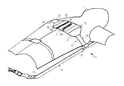
Figure 1 shows the chest compression belt fitted on a patient.
Figure 2 shows a bottom view of a chest compression device that uses
a belt to perform compressions.
Figure 3 shows a top (anterior) view of a belt cartridge used with a belt
drive platform.
3b
CA 02779585 2012-06-06
76452-64D
Figure 4 shows a bottom (posterior) view of a belt cartridge used with
the belt drive platform.
Figure 5 shows a superior view of a belt cartridge used with the belt
drive platform.
Figure 6 shows the belt used in the belt cartridge of Figures 3
through 5.
Figure 7 shows a close-up view of the cover plate used in the belt
catridge of Figures 3 through 5.
Figure 8 illustrates a method of attaching the compression belt to the
drive spool.
Figure 9 shows a close-up view of the spline, the belt and the drive
spool.
Figure 10 illustrates a method of attaching the belt catridge to the belt
drive platform.
Figure 11 illustrates a method of attaching a belt guard to a spindle of
the belt drive platform.
Figure 12 shows a close-up view of the compression belt cartridge.
Figure 13 shows a cross-section of the belt, liner socks and breakable
link.
Figure 14 shows the belt attached to the breakable link.
3c
CA 02779585 2012-06-06
4452-64
Figure 15 shows another cross-section of the breakable link.
Detailed Description of the Inventions
Figure 1 shows the chest compression belt fitted on a patient 1. A chest
compression device 2
applies compressions with the belt 3, which has a right belt portion 3R and a
left belt portion 3L. The
chest compression device 2 includes a belt drive platform 4 and a compression
belt cartridge 5 (which
includes the belt). The belt drive platform includes a housing 6 upon which
the patient rests, a means
for tightening the belt, a processor and a user interface disposed on the
housing. The means for
tightening the belt includes a motor, a drive train (clutch, brake and/or gear
box) and a drive spool
upon which the belt spools during use. Various other mechanisms may be used to
tighten the belt,
including the mechanisms shown in Lach et al., Resuscitation Method and
Apparatus, U.S. Patent
4,774,160 (Sep. 13, 1988) and in Kelly et al., Chest Compression Apparatus for
Cardiac Arrest, U.S.
Patent 5,738,637 (Apr. 14, 1998).
In use, the patient is placed on the housing and the belt is placed under the
patient's axilla
(armpits), wrapped around the patient's chest, and secured. The means for
tightening the belt then
tightens the belt repetitively to perform chest compressions.
The compression belt 3 shown in Figure 1 is provided with a structure that
aids in performing
compressions effectively and efficiently. Specifically, the belt is shaped
like a double-bladed oar.
The wider load distribution sections 16 and 17 of the belt are secured to each
other over the patient's
chest and apply the bulk of the compressive load during use. The narrow pull
straps 18 and 19 of the
belt are spooled onto the drive spool of the belt drive platform to tighten
the belt during use. The
trapezoid-shaped transition sections 20 and 21 reinforce the belt and transfer
force from the pull straps
to the load distribution sections evenly across the width of the load
distribution sections. The narrow
end of a trapezoid faces the pull strap and the wide end of a trapezoid faces
a corresponding load
distribution section.
The pull straps 18 and 19 of the belt are narrow so that the chest compression
device may
perform compressions more efficiently, thus saving battery power and
prolonging the ability of the
device to perform compressions. The narrow pull straps of the belt reduce the
mass of the belt and
reduce the torque necessary to tighten the belt around the patient's chest,
particularly when the means
for tightening the belt tightens the belt by spooling it around a drive spool.
In addition, by using
narrow pull straps, the belt may fit within a narrow channel beam in the belt
drive platform. This
reduces the weight and size of the belt drive platform and increases the
strength of the platform by
allowing a narrower channel beam (see item 45 of Figure 2) to be used with the
platform.
The load distribution sections 16 and 17 of the belt are wider than the pull
straps to allow the
chest compression device to perform compressions more effectively and more
safely. The wider
portions of the belt compress more of the chest, increasing blood flow and
thus performing
4
CA 02779585 2012-06-06
WO 2005/037178 PCT/US2004/033952
compressions more effectively. In addition, the wider portions of the belt
allow more force to be
applied to the patient by evenly distributing pressure on the patient's chest,
thus increasing blood flow
while making chest compressions safer for the patient.
The transition sections 20 and 21 of the belt transfer the tension from the
pull straps to the
load distribution sections and reinforce the belt. Thus, the transition
sections narrow along the lateral
portion of the belt.
The right load distribution section 16 and left load distribution section 17
of the belt are
provided with hook and loop fasteners so that the belt may be secured to the
patient's chest.
(Securing the right and left load distribution sections to each other secures
the belt around the
patient's chest.) Preferably, the hook side of the hook and loop fastener is
located on the anterior load
distribution section of the belt (in this illustration, the left side is
anterior to and superficial to the right
load distribution section) so that the hooks do not contact carpet or other
materials when the belt is
open and splayed on the ground, though the hook and loop fasteners may be
located anywhere on the
load distribution sections of the belt. A handle 32 (more clearly shown in
Figure 2) is provided on the
left end of the belt to aid in placing and removing the belt. The handle and
user interface are located
on the same side of the belt drive platform to make applying and removing the
belt an ergonomic
motion.
An eyelet 33 is provided in the left load distribution section of the belt and
a corresponding
registration peg 34 is provided in the right load distribution section of the
belt. (The peg, eyelet and
hook and loop fasteners may be disposed on either load distribution section.)
To secure the belt to the
patient, the left load distribution section is laid over the right load
distribution section and the eyelet is
aligned with the peg. (The peg fits within the eyelet.) The eyelet and peg
assist the rescuer to
properly register the load distribution sections with respect to each other
and the patient, and thereby
properly position the belt on the patient. The eyelet and peg are also long
relative to the
superior/inferior direction of the patient and are located in the center of
the assembled load
distribution sections. Thus, the eyelet and peg help the rescuer place the
center of the load
distribution sections over the center of the patient's sternum. In addition,
since the right and left load
distribution sections tend to pull away from each other when the belt is
tensioned, the peg and eyelet
further secure the load distribution sections of the belt to each other by
resisting shear forces that tend
to pull the sections apart.
In addition, the peg and eyelet enable the rescuer to repeatably release the
belt and then
secure the belt around the patient such that the belt has the same length each
time the belt is secured
around the patient. (During use the rescuer may need to release the belt and
re-secure the belt around
the patient without replacing the cartridge.) Since the belt maintains the
same length, the chest
5
CA 02779585 2012-06-06
WO 2005/037178 PCT/US200.4/033952
compression device is much more likely to achieve the same depth of chest
compressions after the
belt has been re-secured as compared to before the belt has been re-secured.
The combination of hook and loop fasteners and the eyelet/peg fastener
provides for a means
for securing the belt around the patient. The same combination allows a
rescuer to rapidly and easily
release the belt. The rescuer may release the belt, even during compressions,
by grasping the left end
of the belt and lifting the left load distribution section from the right load
distribution section. Thus,
the securing mechanism is also an emergency release mechanism. To further
enhance safety, the
eyelet may be provided with an electrical contact switch, optical sensor or
other electrical or
mechanical means for determining whether the peg is inserted into the eyelet.
Thus, a chest
compression device with the appropriate software or hardware can sense whether
the peg is fully
inserted into the eyelet. If the peg is not in the eyelet, then the chest
compression device will not
perform compressions. The system will alert the operator if proper
registration is not detected so that
the operator may re-fit the belt.
Figure 2 shows a bottom view of the belt drive platform 4 and shows the
housing 6, a belt
cartridge 5 attached to the housing and a means for tightening the belt
disposed within the belt drive
platform. The means for tightening the belt may comprise a drive spool 42
attached to the belt and to
a motor. The drive spool is shown in phantom to indicate its position beneath
the cover plate. The
motor and associated components are located within the belt drive platform.
The belt drive platform is provided with a control system that controls how
the belt is
wrapped around the drive spool. For example, the drive spool is controlled so
that some of the belt is
left wrapped around the drive spool between compressions. When the means for
tightening has
loosened the belt around the patient, just before beginning the next
compression, a length of the belt
corresponding to one revolution of the drive spool is left wrapped around the
drive spool. Thus, the
belt will maintain its curled shape, reducing the chance of causing folds in
the belt during
compressions and increasing the efficiency of spooling the belt around the
drive spool.
The housing serves as a support for the patient. Handles 43 provide for easy
transport of the
housing and of the patient while on the housing. The belt cartridge has a
cover plate 44 that fits
within a channel beam 45 in the belt drive platform, thus securing the belt
cartridge 41 to the belt
drive platform 4. Labels 46 are placed on the housing and cover plate to
indicate the proper
alignment of the cover plate. The cover plate is secured to and aligned within
the channel beam by
the use of retainer clips or snap latches 47, 48, 49 and 50 which fit between
corresponding paired
bosses or detents in the housing. Tabs integrally formed with the snap latches
extend into slots
disposed in the housing of the belt drive platform. The cover plate is also
aligned and secured within
the channel beam by the use of hooks 51, 52, 53 and 54 which fit into
corresponding apertures in the
6
CA 02779585 2012-06-06
WO 200;/037178 PCT/US2004/033952
housing. In addition, the cover plate is also provided with additional
labeling 55 to provide warnings,
manufacturer information, trademarks or advertising.
Figures 3, 4 and 5 show the belt cartridge 41. The belt cartridge is
disposable so that there is
no need to clean the belt, or other elements of the cartridge, after use.
Thus, the belt cartridge reduces
the exposure of subsequent patients and users to bodily fluids or other
contaminants. If necessary, the
cartridge may be replaced while the patient is still on the belt drive
platform. In addition, since the
belt cartridge is disposable the belt may be made of materials that readily
conform to the shape of an
individual patient, but have a shorter service life.
The cartridge includes a belt 3, a compression pad 65 attached to the belt, a
belt clip, key or
spline 66 for attaching the belt to a drive spool, a cover plate 44 and belt
guards 67 and 68 rotatably
attached to the cover plate via hinges 69 and 70. The belt guards are
removably secured over spindles
that are attached to the belt drive platform. A liner, sleeve or sock is
disposed over the belt, as shown
in Figure 5. The belt is threaded through slots 71 and 72 disposed in the belt
guards 67 and 68. With
regard to the belt 3, the right portion 3R and the left portion 3L of the belt
share pull straps 18 and 19
and each have a load distribution section 16 and 17 and a transition section
20 and 21. Each load
distribution section of the belt is provided with hook and loop fasteners so
that the belt may be
secured around the patient's chest. Additionally, as described above, an
eyelet 33 is provided in the
left load distribution section and a corresponding peg 34 is provided in the
right load distribution
section (see Figure 5). Preferably, the pull strap sections comprise a single
strap.
The pull straps of the belt are secured to the drive spool of the belt drive
platform with the
spline 66, which is attached to the pull straps of the belt. The spline fits
within a slot provided in the
drive spool. When the drive spool rotates, the pull straps spool around the
drive spool. The
compression belt then tightens and is pulled onto the patient's chest, thereby
accomplishing
compressions.
The pull straps 18 and 19 of the belt are threaded through the belt guards 67
and 68 which are
rotatably attached to the cover plate 44. The belt guards and cover plate are
fashioned from a
lightweight but strong plastic. The cover plate and belt guards are designed
to allow the belt cartridge
to be removably attached to the belt drive platform and to protect the belt
during use. Specifically,
the cover plate is provided with snap latches 47, 48, 49 and 50 that fit
between corresponding paired
bosses or detents on the housing. Integral tabs extend from the snap latches
and fit into corresponding
slots in the housing. The cover plate is also provided with hooks 51, 52, 53
and 54 that fit into
corresponding apertures in the housing of the belt drive platform. The snap
latches and hooks are
designed so that the cover plate is removably attached to the belt drive
platform without the use of
tools. The snap latches and hooks may have a variety of shapes and forms. The
snap latches and
hooks may also be asymmetrical with respect to the cover plate, thus making it
possible to fit the
7
CA 02779585 2012-06-06
452-64
cover plate on the belt drive platform in only one orientation. To increase
the ease of use of the
cartridge, the cover plate is provided with labels 46 to indicate the desired
orientation of the cover
plate with respect to the belt drive platform.
Below the load distribution sections of the belt is a compression pad 65 that
affects the
distribution of compression force and assists in performing chest
comtressions. An example of a
chest compression pad may be found in our US Patent No. 6,939,314 (Sep. 6,
2005). In one
embodiment the compression pad is a three-sectioned bladder filled with foam.
The compression pad
is located on the belt so that it is centered over the patient's chest when
the belt is in use. The
compression pad is disposed below the load distribution sections of the belt
and is removably attached
to the belt with double-stick tape, hook and loop fasteners or comparable
fastening means. The
compression pad is also disposed inside the liner sock.
Additional safety features may be provided with the compression belt cartridge
41. For
example, spreader bars or reinforcing plates 87 may be attached to the
transition sections of the belt
with stitches 88. (The reinforcing plates may be attached to the transition
sections of the belt by any
suitable method.) The reinforcing plates reinforce the transition sections of
the belt and help prevent
the transition and load distribution sections from twisting, bending, folding
or otherwise deforming
with respect to the pull straps, except in regard to the ability of the belt
to wrap around the patient's
chest. The reinforcing plates are made of a hard plastic or other non-
resilient, though flexible
material.
The belt also may be provided with one or more breakable couplings or
breakable links 89 on
one or both sides of the load distribution or belt transition sections. The
breakable link 89 or links are
interposed between sequential portions of the belt such that the belt
separates if a link breaks. The
link is designed to break at a predetermined tension. If the belt experiences
an unsafe amount of
tension, then a link breaks, the belt separates and the patient is thereby
protected from excessive
forces. What constitutes an unsafe amount of tension or excessive force
varies, depending on the
patient and the device and belt used, but is in the range of about 200 pounds
to about 500 pounds as
measured in the area of the belt to the side of the patient. Preferably, the
link is designed to break
under about 300 pounds of tension as measured in the area of the belt to the
side of the patient. In
addition, the link may be designed to reattach to itself or to a clip or other
mating fastener after
failure. Thus, in the event of link failure, the belt may be re-attached
quickly and compressions may
be restarted with minimal delay.
To prevent the load distribution sections from twisting relative to the other
sections of the
belt, the links may be designed to also serve as swivel joints, or the belt
may be provided with
additional swivel joints along the belt. The swivel joints connect the pull
straps to the belt transition
S
CA 02779585 2012-06-06
WO 2005/037178 PCT/US2004/033952
sections. The swivel joints allow the load distribution sections to twist
relative to the pull straps,
about the longitudinal axis of the belt, without twisting the pull straps
themselves.
Another safety feature is a liner sock 90 for the belt (see Figure 5). The
liner sock surrounds
the portions of the pull straps, as well as the compression pad, that contact
the patient thereby
protecting the patient from friction as the belt moves during compressions.
The liner socks are
attached to the belt guards around the belt guard slots so that hair, other
body parts or other foreign
objects cannot become caught in the belt guard slots. On the other end, the
socks are disposed around
and are attached to the load distribution sections of the belt.
In use, the belt spline is inserted into the drive spool of the belt drive
platform. The cover
plate of the cartridge is then inserted into the channel beam of the belt
drive platform and fixed into
place via the hooks and snap latches. The belt is wrapped around the patient,
with the load
distribution sections secured over the patient's chest. Thus, the chest
compression device performs
compressions by repetitively tightening the belt.
Figure 6 shows the belt 3 used in the belt cartridge of Figures 3 through 5.
When laid out, the
belt has the shape of a double-sided oar or paddle. As described above in
reference to Figures 3
through 5, the right portion 3R and the left portion 3L of the belt each have
a load distribution section
16 and 17, a transition section 20 and 21 and pull straps 18 and 19. The pull
straps are narrow with
respect to the load distribution sections. The load distribution sections are
disposed opposite each
other, and each load distribution section of the belt is provided with hook
and loop fasteners 96 so that
the belt may be secured to the patient's chest. An eyelet 33 is provided in
the left load distribution
section and a corresponding peg 34 is provided in the right load distribution
section to further secure
the belt around the patient. (The peg and eyelet may comprise a variety of
shapes and sizes; for
example, the peg may be a post and the eyelet a round grommet.) In addition, a
spline 66 is attached
to the belt by any suitable manner. The spline fits within a slot provided in
the drive spool of the belt
drive platform. Thus, when the drive spool rotates, the pull straps will spool
around the drive spool.
The transition sections 20 and 21 of the belt are disposed opposite each other
and are
provided with corresponding thin (1/16 inch) reinforcing plates 97 and 98 of
flexible plastic that
reinforce the belt. (The plates may comprise different materials and may be
thicker or thinner, or
even of varying thickness, depending on the material used and the desired
stiffness of the transition
sections; however, plates with a thickness of about 1/4 inch or less are
preferred.) The reinforcing
plates mitigate the effects of stress concentrations in the belt, stress voids
in the belt, belt creasing,
belt wadding and other problems caused by using a compression belt that has a
non-uniform width.
The reinforcing plates are attached to the transition sections of the belt and
the shape of the
reinforcing plates conforms to the shape of the transition sections of the
belt. (The reinforcing plates
may be attached to the transition sections by any suitable means and may be
located above, below or
9
CA 02779585 2012-06-06
WO 2005/037178 PCT/US200-l/033952
within the transition sections.) The reinforcing plates also bend to conform
to the shape of the
patient's torso during compressions. As the plates bend around the patient,
the bending stiffness of
the plates along the other axes of the plates increases. To provide smooth
compressions along the
patient's chest, one or more edges of the reinforcing plates may be bent
outwards and away from the
patient (like ski tips).
The belt material of the pull straps, the load distribution sections and the
transition sections
has a constant thickness of about 0.010 inches and is made of a custom, fiber-
reinforced material that
can be manufactured by a number of belt manufacturers. Our belt is a material
made from
unidirectional layers of high-strength fibers held together with a resin. (The
fibers are Spectra 2000
fibers available from Allied Signall, Inc., but may also be carbon, Kevlar''"'
and other fibers.) Our
custom belts do not stretch or break under heavy loads, and are resistant to
bodily fluids, aging,
humidity and temperature.
The belt may also be made of a flat metal or rounded metallic cable, nylon,
sail cloth or other
strong and flexible materials. The belt material may also include layers of
additional materials such
as TyvekT"' (high-density, spun bonded polyethylene) or Teflon TM
(polytetrafluoroethylene) directly
bonded to the primary belt material.
The custom belts used with the belt cartridge have 4 laminated layers of
fibers oriented at 0,
90, 6 and -6 degree angles with respect to the long axis of the belt. Placing
at least some of the layers
obliquely with respect to the long axis of the belt improves belt performance
and longevity. The resin
holding the fibers together is about 60% to 70% of the volume of the material.
An additional layer is
laminated on the outside of the belt to improve water resistance and lessen
friction during use. A belt
designed with laminated fibers at different orientations with respect to the
long axis of the belt is less
likely to stretch during compressions. The above belt has an average stiffness
of about 77,000 pounds
per inch per one-inch length of belt, as measured along the longitudinal axis
of the belt, and thus does
not stretch during compressions.
The belt (or cable) may be pre-conditioned before distribution or sale. The
cartridge and belt
may be disposed on a test platform and the cartridge and belt tested before
being sold. This process
pre-conditions the belt. Pre-conditioning the belt deforms the belt to the
shape of the spool shaft,
which allows for more efficient spooling of the belt during compressions.
Preconditioning also helps
prevent the belt from deforming during use. Thus, preconditioned belts will
perform consistently
during use. In addition, the belt is at least partially spooled around the
drive spool during storage so
that the pull straps are set to the shape of the drive spool prior to use.
The overall belt and belt cartridge are sized and dimensioned to be used with
95% of all body
sizes. (Only extremely small or large patients may have difficulty benefiting
from a device that
includes the compression belt cartridge.) The pull straps are about 2 inches
wide (along the superior-
CA 02779585 2012-06-06
WO 2005/037178 PCT/US2004/033952
inferior dimension of the patient, as indicated by the direction of arrows 99)
and about 40 inches long
(along the medial-lateral dimension of the patient, as indicated by the
direction of arrows 100). The
load distribution sections of the belt are about 8 inches wide and about 12
inches long. The transition
sections of the belt are about 6 inches long and taper gradually between the
pull straps and a load
distribution section; thus, the transition sections have a trapezoidal shape.
All sections of the belt
material have a constant thickness of about 0.010 inches, with a tolerance of
0.001 inches. The belt
may be thinner to reduce the weight of the cartridge and the overall device,
though the belt may be as
thick as 0.25 inches.
Because the belt is thin, the overall weight of a compression device is kept
to a minimum.
Using a thin belt also spools less material onto a drive spool during use.
This reduces the overall
diameter of the drive spool plus belt material, thereby reducing the amount of
torque necessary to
operate the chest compression device. Thus, using a thin belt also saves
energy, thereby increasing
the life of a battery used to power a chest compression device.
Figure 7 shows a close-up view of the cover plate 44 used in the belt
cartridge of Figures 3
through 5. As already described, the cover plate is designed to allow the belt
cartridge to be
removably attached to the belt drive platform and to protect the belt during
use. Specifically, the
cover plate is provided with hooks 51 and 52 that fit within apertures
provided in the housing. The
cover plate is also provided with snap latches 47 and 48 which fit securely
between corresponding
paired bosses or detents that extend from slots disposed in the housing. Tabs
integrally formed with
the snap latches extend into the slots when the cover plate is secured to the
housing.
To reduce weight, the cover plate is fashioned from a thin plate of plastic.
To increase
strength, the cover plate is provided with intersecting reinforcing ribs 106
(also shown in Figure 3)
that reinforce the cover plate and help the cover plate to resist the force of
compressions. Additional
aluminum reinforcement braces 107 (also shown in Figure 3) are provided to
further reinforce the
cover plate. The reinforcement braces span the height of the cover plate to
provide the cover plate
with additional strength. The reinforcement braces also brace the channel
beam, thereby protecting
the belt drive platform from deforming under high forces.
The cover plate is provided with opposing curved extensions 108 and 109 so
that the cover
plate fits precisely within the belt drive platform. The curved extensions, as
well as the overall size
and dimensions of the cover plate, prevent the belt cartridge from being used
with devices not
designed to receive the belt cartridge. Thus, the cover plate also helps
ensure that the cartridge will
be used safely.
Rotatably attached to the curved extensions of the cover plate are belt guards
67 and 68 that
protect the user, belt drive platform and belt when the chest compression
device is in use. The belt
guards are removably secured around the spindles during use. The belt guards
are wider than the belt,
11
CA 02779585 2012-06-06
WO 2005/037178 PCT/US2004/033952
and the pull straps are threaded through slots 71 and 72 disposed in the belt
guards. Thus, during use,
the belt slides within the belt guards and over the spindles. The spindles, in
turn, rotate within the belt
drive platform. The spindles also rotate underneath the belt guards, sliding
against the belt guards
where the belt guards are disposed against the spindles.
On each end of the cover plate, fingers or pawls 110 and 111 hook around
corresponding
catches or ratchets 112 and 113. The ratchets are attached to corresponding
hinges 69 and 70, though
may be attached to the corresponding belt guards. The pawls are attached to
the cover plate and
prevent the belt guards from curling away from the cover plate. However, a
user may (preferably
without tools) apply a force sufficient to pull the ratchets away from the
pawls as the hinges rotate,
thereby allowing belt guards more freedom to rotate outwardly, away from the
cover plate. The user
may also re-engage the pawl and ratchet so that the belt guards are once again
prevented from curling
outwardly.
The various components of the belt cartridge may be differently oriented with
respect to each
other. For example, the compression pad may be disposed beneath the liner sock
instead of inside the
liner sock. In other embodiments, if the geometry of the belt drive platform
changes, then the
compression belt cartridge may be changed accordingly. For example, if the
drive spool is located to
one side of the belt drive platform, then the spline would be located outside
the belt guards (instead of
between them) and the rest of the cartridge would be adjusted to fit to the
housing and belt drive
platform. The belt may have other shapes; for example, the belt may have more
than one narrow
region. (If the belt drive platform uses more than one drive spool then the
belt may have more than
one set of pull straps.) In addition, other means for tightening the belt may
be used, such as multiple
motors and drive spools, pistons, scissors mechanisms or other mechanical
actuators.
Figures 8 through 11 illustrate devices and methods for operably inserting the
belt cartridge
into the housing of the belt drive platform. Figure 8 illustrates a user 124
inserting the belt spline 66
into the slot 125 in the drive spool 42. The user sets aside the cover plate
44 and inserts the front end
127 of the spline into the drive spool slot 125 in the direction indicated by
arrow 128. The user then
fits the back end 129 of the spline into a guide slot 130 disposed in a guide
plate 131, which serves to
further secure the spline in place, and secures the back end of the spline
into the drive spool slot. The
user then secures the cover plate over the channel beam 45. After securing the
cover plate in the
channel beam, the belt guards 67 and 68 attach to opposing rods, rollers or
spindles 132 fixed to the
sides of the belt drive platform. The spindles decrease friction as the belt
travels along the spindles.
Figure 9 shows a close-up view of the spline 66, the guide plate 131 and the
drive spool slot
125. The spline is provided with a particular shape so that the spline will
fit more securely within the
drive spool slot. The shape of the spline also discourages the use of splines
not designed by the
12
CA 02779585 2012-06-06
WO 2005/037178 PCT/US2004/033952
manufacturer and discourages placement of the spline in an incorrect
orientation. Thus, the spline is
keyed to the drive spool slot.
Specifically, the spline 66 is provided in the form of a rectangular rod or
bar made of a hard
plastic or a metal. The front end 127 of the spline is provided with a
protruding foot, boss or catch
143 shaped to fit into the front end 144 of the drive spool slot. Likewise,
the back end 129 of the
spline is provided with a second protruding foot, boss or catch 145 shaped to
fit into the back end 146
of the drive spool slot. (The spline may have other shapes to accommodate
differently shaped slots in
the drive spool.)
The drive spool slot is provided with corresponding recesses 147 and 148 to
accommodate
the front and back catches on the spline respectively. Thus, the spline
resembles a key and can
function in a similar manner with respect to the use of the chest compression
device. In addition to the
catches, slots and recesses shown, the spline is further held in place with
one or more detents in the
belt drive platform that engage the front or back catches on the spline. The
detents also serve as
catches inside the belt drive platform that prevent the drive spool from
rotating when the spline is not
inserted in the drive spool slot. Thus, the device will not operate unless the
spline is correctly inserted
into the drive spool slot. In addition, the front end of the spline engages an
electromechanical switch
when inserted into the slot. When the spline engages the switch, a signal is
generated (or interrupted)
that informs the control system that the clip is present and properly engaged.
Additionally, the belt
drive platform may be provided with hardware or software that detects whether
the spline is correctly
inserted and informs the user of incorrect insertion and prompts the user to
re-insert the spline if the
spline is not correctly inserted.
The spline, cover plate or belt drive platform may be provided with a means
for ensuring that
a particular compression belt cartridge will only be used once (that is, used
on only one patient during
one rescue attempt). For example, the spline may be provided with a breakaway
or deformable tab
that, on insertion into the drive spool slot, renders the spline unusable
after the spline has been
removed from the spool shaft slot. Additionally, the spline may have a means
for identifying whether
the spline was produced by an approved manufacturer or whether the spline
previously had been
attached to the drive spool slot of a belt drive platform. For example, an RF
identification tag or other
wireless communication mechanism could be attached to the spline, wherein the
RF tag transmits data
corresponding to a unique identifying number. A magnetic strip may also be
attached to the spline
that stores a unique identifying number. A given belt drive platform will
operate only if the
identifying number corresponds to a number provided to the platform by the
manufacturer and only if
that number has not been used with the belt drive platform in the past. If the
belt drive platform is
connected to a network, then any belt drive platform connected to the network
may be programmed to
recognize when a particular belt cartridge has been used with any other belt
drive platform.
13
CA 02779585 2012-06-06
WO 2005/037178 PCT/US200-t/033952
Moreover, the belt drive platform may be programmed to alter the identifying
number on the spline,
thereby rendering the cartridge unusable with any other belt drive platform.
If this feature is
implemented, the belt drive platform may be accompanied by an over-ride
feature that allows a used
cartridge to be used again. Thus, in the unusual situation where multiple
heart attack victims are
encountered or where a used cartridge is the only available cartridge, the
cartridge may be used again.
To further secure the spline within the drive spool slot, a collar or guide
plate 131 is provided
around one or both ends of the drive spool 42. The guide plate is provided
with a guide plate slot 130
through which the back end of the spline is inserted. After the spline is
inserted, the guide plate is
adjustable to firmly secure the spline within the drive spool slot. A user may
manually move the
guide plate sufficiently to insert the spline into and remove the spline from
the slot.
The guide plate may be spring loaded and pushed into the wall of the channel
beam to make
room for inserting the spline, or the guide plate may be rotated (or rotated
and pushed) to secure the
back end of the spline within the drive spool slot. If the guide plate is
spring loaded, the spring
comprises a means for providing a biasing force to the guide plate; however,
other means for biasing
the guide plate may be used, such as a flexible tab. In any case, the guide
plate may be disposed in
relation to the drive spool such that the spline may not be inserted into or
removed from the drive
spool slot unless the guide plate or the drive spool is moved. This ensures
that the spline will remain
secured to the drive spool during use and during storage (while the drive
spool is rotating and while
the drive spool is stationary).
In use, the spline is inserted into the drive spool slot as shown by arrows
149 and 150. When
the drive spool rotates, the belt 3 wraps or spools around the drive spool,
thereby tightening the belt.
As the belt is tightened the patient's chest is compressed. The patient's
chest is decompressed as the
drive spool rotates in the opposite direction, thereby allowing the belt to
unwind and relax. After use,
the process of inserting the belt may be reversed to detach the belt cartridge
from the belt drive
platform. Thus, the belt cartridge may be replaced after each use of the belt
drive platform.
Preferably, all of the attachment mechanisms are releasable, as described
above, so that the operator
can replace the belt without the use of special tools.
Figure 10 illustrates a method of attaching the belt cartridge to the housing
of the belt drive
platform. The belt cartridge cover plate 44 is attached to the channel
(established by beam 45) in the
belt drive platform. Labels 46 allow the user to easily align the cover plate
within the channel beam.
Hooks 53 on the cover plate fit into corresponding apertures 158 in the belt
drive platform. Belt
guards 67 are removably disposed around spindles 132. (The spindle is shown in
phantom to indicate
its position underneath the belt guard and within the belt drive platform). In
addition, snap latches 47
fit within paired detents that extend from the edges of slots 159 in the belt
drive platform. Tabs
extending from the snap latches fit within the slots themselves.
14
CA 02779585 2012-06-06
WO 2005/037178 PCT/US2004/033952
The labels include an arrow 160 disposed in a recess 161 in the belt drive
platform and an
arrow 162 disposed in a recess 163 on the cover plate 44. The cover plate is
correctly aligned within
the channel beam when the arrow on the belt drive platform is pointing at the
arrow on the cover
plate. The hooks and snap latches on the cover plate then fit within
corresponding apertures and slots
within the belt drive platform.
The snap latches are designed so that an audible click is heard when a snap
latch is fully
inserted into a corresponding slot. The snap latches may be designed so that
they bend as they fit
between the detents. When fully inserted, a flange on the end of the snap
latch slips with respect to
the detents, making an audible click when the flange strikes the edge of the
slot. In addition, the
hooks and snap latches may be aligned so that the belt cartridge only fits in
one orientation with
respect to the belt drive platform. For example, the snap latches or hooks may
be spaced
asymmetrically with respect to cover plate so that if the cover plate is
incorrectly oriented the cover
plate will not fit into the channel beam.
Figure I1 shows a method of attaching a belt guard 68 to a spindle 132 of the
belt drive
platform 4. The cover plate 44 has already been secured to the belt drive
platform, though the hinges
70 allow the belt guard to rotate with respect to the belt drive platform and
cover plate. The belt
guards are provided with a hook-shape so that they securely attach around the
spindles 132 fixed to
the belt drive platform. The user may secure the belt guards around the
spindles, as indicated by
arrow 173.
In use, the belt guards protect the patient, rescuer, belt, belt cartridge and
belt drive platform.
The belt guards prevent foreign objects from entering the belt drive platform
and becoming caught in
the channel beam. Thus, a user's fingers or clothes, patient's clothes or body
parts, or debris located
near the site of emergency cannot enter the belt drive platform and damage the
patient, the rescuer or
the various parts of either the belt drive platform or the belt cartridge.
Figure 12 shows a close-up view of the compression belt cartridge 41.
Instructions 174 on
how to deploy the compression belt cartridge or the belt drive platform are
printed on the outer
surface of the belt 3, belt liner, cover plate, compression pad or any other
component of the
compression belt cartridge. Specifically, indicia including pictorial
instructions and written
instructions (including Braille) show the rescuer how to correctly secure the
compression belt around
the patient.
Markings 175 on the outside of the belt liner indicate when the belt straps
have been twisted.
The markings may be lines that are oblique or skew to the longitudinal axis of
the belt or belt liner,
but may also be areas of solid colors on one side of the belt or belt liner.
Preferably, less than the
entire surface of one side of the belt liner is painted or marked. (Excessive
ink, dye, transfer or
adhesive elements, such as stickers, cause the liner to become too stiff,
thereby significantly
CA 02779585 2012-06-06
WO 2005/037178 PCT/US200-t/033952
increasing the chances that the belt liner will wear prematurely.) The
markings 175 may also serve as
a means for identifying the manufacturer; for example, the markings may show
the manufacturer
name or other advertising information.
In addition, markings are provided to show a rescuer how to correctly align
the compression
belt and the belt drive platform with the patient. A yellow or other brightly
colored orientation line is
disposed along the superior edge of the load distribution sections of
compression belt, parallel to the
longitudinal axis of the compression belt. When the compression belt is
correctly placed on the
patient the yellow line will line up with the patient's axilla (armpits).
Furthermore, the yellow line
also lines up with a corresponding yellow strip disposed on the housing of the
belt drive platform.
Thus, a rescuer can easily visualize when the belt and belt drive platform are
correctly oriented with
respect to the patient and to each other. (Other marking schemes may also be
used in relation to other
anatomical landmarks such that the placement of the orientation lines may be
varied.)
Similarly, the alignment peg on the load distribution section indicates that
the patient should
be aligned on the center of the belt drive platform and that the load
distribution sections should be
aligned on the center of the patient's chest. Thus, when the belt is placed
correctly, the peg lies over
the center of the patient's sternum. Preferably, the peg is long relative to
the superior-inferior
direction such that the longitudinal axis of the peg lies directly over and
parallel to a superior-inferior
line in the center of the patient's sternum.
The instructions, alignment arrows and cartridge components are color coded
(or otherwise
uniquely marked) to be easier to read and understand, or to indicate the
purpose of the instructions.
For example, the eyelet 33 and peg 34 are colored yellow (or otherwise
uniquely colored or marked)
to indicate that they mate. The belt cartridge also may be provided with
colored warning or
instruction labels 176 (multiple colors and color schemes may be used).
Examples of warning or
instruction labels include: "Align the armpits onto the yellow line,"
"LifeBand straps 90 degrees to
platform," "Do not cut," "Do not twist" or "Single patient use do not reuse."
Each warning may be
assigned a different color, such as red, blue, black and gray.
The devices and methods shown above in reference to the figures may be
modified. For
example, the spline may be a hemisphere and attach to a corresponding
hemisphere on the drive
spool. The slot in the drive spool may extend through the drive spool and the
belt threaded through
the slot. The spline may also be provided with arms that clip around the drive
spool and thereby
secure the spline to the drive spool. The spline may be provided with magnets,
a collar, detents or
other latching features to ensure that the spline remains attached to the
drive spool during use. In the
case of a magnet, the wrapped portion of the belt around the drive spool holds
the belt in place when
the load becomes large.
16
CA 02779585 2012-06-06
WO 2005/037178 PCT/US2004/033952
The hook and loop fasteners may be replaced with buckles. The cartridge may be
provided
with a processor and a speaker, with the processor programmed to give audio
instructions to the user.
In addition, other means for tightening the belt may be used, such as multiple
motors and drive
spools, pistons, scissors mechanisms or other mechanical actuators.
Similarly, the drive spool or drive spools may have different shapes. If so,
then the
connection between the pull straps and the drive spool may have to be altered
to accommodate the
new drive spool shape. For example, a drive spool may have a conical shape and
the pull straps
replaced with pull cables or with pull straps made of a material without
resin. In this case, the belt or
cables may be fixedly attached to the drive spool.
Figures 13 through 15 show close-up views of the belt 3, the breakable link 89
and the liner
socks 182 and 183 surrounding the portions 3R and 3L of the belt that contact
the patient and also
shows the breakable link 89. (The peg 34, eyelet 33, spline 66 and various
sections of the belt 16, 17,
18, 19, 20 and 21 are shown for reference. The compression pad and cover plate
are not shown in
order to more clearly show the belt liner.) The loosely fitted liner socks
protect the patient from
friction. The belt generates friction along the surface of the patient as the
belt repetitively compresses
the patient's chest. Without some means for reducing the friction, the belt
would likely cause injury
during compressions, such as abrasions, contusions or other compression-
related injuries. In addition,
friction increases the energy required to operate the compression device and
thereby reduces battery
life. The liner socks protect the patient and increase energy efficiency by
allowing the belt to easily
slide along the liner, with the liner only moving slightly against the
patient's chest. (Some bunching
of the liner socks may occur during compressions.)
The liner socks are tubes of TyvekTM (high-density, spun bonded polyethylene)
that are
attached to the belt cartridge to form socks around the right 73 and left 3L
portions of the belt. (The
liner socks may comprise other materials that are water resistant and have a
similar coefficient of
friction to TyvekT"1, TeflonTM, or like substances. The liner socks may also
have multiple layers of
material; that is, socks within socks.) The left sock 182 is attached to the
left belt guard 68 at one end
and to the left load distribution section 17 of the belt at the other end. A
hole in the left sock allows
the peg 34 to be inserted into the eyelet 33. The left sock is attached to the
belt at any point near the
free end of the load distribution section. The right sock 183 is attached to
the right belt guard 67 at
one end and to the right load distribution section 16 of the belt at the other
end. The right sock is
attached to the belt at any point near the free end of the right load
distribution section. The right sock
wraps around the compression pad 65 and surrounds the breakable link.
The breakable link 89 is a cylinder made of aluminum or other suitable
material. The central
portion 190 of the cylinder has a smaller diameter than the end portions 191
and 192 of the cylinder.
Since the link will break at the thinnest portion of the cylinder, the amount
of force required to break
17
CA 02779585 2012-06-06
WO 2005/037178 PCT/US2004/033952
the link is precisely controlled by setting the radius of the central portion
190 of the cylinder. If the
link 89 breaks under tension then the two remaining ends of the link remain
within the sock. The
liner sock thus reduces the chance that a broken link will lash out and cause
injury to the patient or
bystanders. In addition, a separate bag or sleeve 184 may be attached to the
belt near either end of the
link. The bag surrounds the breakable link and contains the link in the event
that the link breaks.
The link or links attached to the belt may be provided with additional
features. For example,
a link may be additionally designed to serve as a swivel joint. The swivel
joint link connects the pull
straps to the belt transition sections of the belt. The swivel joint link
allows the load distribution
sections to twist relative to the pull straps, about the longitudinal axis of
the belt, without twisting the
pull straps themselves. (The pull straps are sufficiently stiff that they do
not twist during use.) The
swivel joint link helps prevent the device from malfunctioning as a result of
the pull straps becoming
twisted and helps prevent the link from breaking due to shear forces or
twisting forces. In other
devices, separate swivel joints are provided and attached to the belt as
described above. For these
devices the swivel joint and the link may be connected to each other, but may
also be disposed at
separate locations on the belt.
In addition, a link or swivel link may be designed to be re-engaged (or to be
re-attached to the
belt) if one or more links do separate. For example, the link or swivel link
may be attached to the belt
with a clip that fails at a pre-determined force, but that can be re-attached
to the belt. Similarly, the
swivel link may be provided in two pieces joined by a joint that separates at
a pre-determined force,
but that can be re-attached to each other. (Other re-attachable links or
swivel link designs may also be
used.) Thus, in the event of a link failure during chest compressions, the
entire belt cartridge need not
be replaced. Instead, the problem that caused the failure can be addressed,
the failed link or links
quickly re-engaged or re-attached and chest compressions then resumed. The re-
attached link will fail
at the same force as the force required to cause the link to originally fail.
The detachable link may comprise a detachable device operably connected to a
force sensor,
pressure sensor or strain gauge. The detachable device is highly resistant to
breaking under force, but
the detachable device will separate when the force sensor, pressure sensor or
strain gauge measures an
excessive force. Such a detachable device may be designed so that a user may
reattach the link to
itself or to the belt, thereby allowing the user to restart compressions
quickly.
Figure 14 shows the belt 3 attached to the breakable link 89. The breakable
link is located on
the belt in a place where the belt tension most closely corresponds to the
actual load on the patient.
Thus, the breakable link 89 is located between the pull straps and the
transition-section of the belt.
The breakable link may be located elsewhere on the belt, though the link would
have to be adjusted to
break at a different amount of belt tension since the tension and sheer forces
on the link would be
18
CA 02779585 2012-06-06
WO 2005/037178 PCT/US2004/033952
different, Multiple links may be provided on either side of the belt.
Preferably, one link is provided
on each side of the belt relative to the patient.
The link is designed to break in the presence of excessive tension (over about
200 pounds to
about 500 pounds on one side of the patient, and preferably at about 300
pounds). The breakable link
breaks cleanly under excessive tension and experiences little plastic
deformation before breaking.
Thus, if the belt experiences excessive tension, the link will break, the belt
will separate and the
patient will be protected from excessive forces.
To attach the link to the belt, the belt is separated into two sections and
corresponding flaps
185 and 186 near opposing ends of each section are folded over themselves to
form pockets in each
belt section. The pockets are held in place by stitches 187. A pin 188 is
disposed within each pocket
and held in place by the stitches. The pins are exposed in the area of holes
189 that are provided in a
corresponding end of each pocket. The holes provide space to receive the ends
of the link and allow
the pins to be threaded through apertures provided in the link. (The unexposed
portions of the pins
are shown in phantom to indicate their position inside the pockets and inside
the link.) Thus, a pin
connects a section of the belt to the link and the belt sections are thereby
connected to each other via
the link. The link is designed so that the center of the link will break,
thereby separating the belt,
before the pins or any other part of the link will break.
Figure 15 shows another cross-section of the breakable link. The breakable
link 89 is an
aluminum cylinder. The central portion 190 of the cylinder has a smaller
diameter than the end
portions 191 and 192 of the cylinder. Since the link will break at the
thinnest portion of the cylinder,
the amount of force required to break the link is precisely controlled by
setting the cross-sectional
area of the smallest part of the central portion 190 of the cylinder. The
material used to make the link
also controls the force required to break the link. Different materials will
break at different levels of
force depending on a number of factors, including the cross sectional area of
the link, the type of alloy
used, whether the link is heat treated, the type of surface finish provided
and the like.
Each end portion of the cylinder is provided with a hole 193 to accommodate
the pins. The
holes are drilled from either side of the cylinder with a conical drill. The
conical drill creates
opposing ridges 194 in the center of each hole. A pin contacts the link in the
area of the ridges so that
the pin is loaded at a point. This orientation prevents excessive forces from
developing in directions
other than in the direction the link is intended to break. The combination of
the conical holes and the
pins permit the link to bend or break only in the direction the link is
intended to break. To further
reduce bending or shear forces, the pins and/or the link are coated with
Teflon T11
(polytetrafluoroethylene) so that the pins may wobble with minimal friction
within the link holes.
The breakable link has a length of 0.942 inches, has a radius of 0.310 inches
at the end
portions and a radius of 0.088 inches at the thinnest central portion. The end
portions of the link are
19
CA 02779585 2012-06-06
WO 2005/037178 PCT/US2004/033952
0.310 inches long each and the central portion of the link is 0.322 inches
long. The thinnest central
portion of the link is 0.042 inches long (and is part of the overall 0.322
inch length of the central
section). An aluminum link of these dimensions will break when about 300
pounds of force is
applied along the long axis 195 of the link. The dimensions of the link may be
varied to vary the
force required to break the link, preferably about 300 pounds for the
detachable device and belt
cartridge shown in Figures 3 through 5. In addition to aluminum, the link may
be made of a variety
of materials, including other metals (such as steel or magnesium), polymers,
composites or fibers.
However, the link must predictably break when exposed to a given force applied
in a given direction.
Other devices and methods may also be used to increase the safety of using a
belt to perform
chest compressions. For example, other forms of reducing the coefficient of
friction of the belt may
be used. The liner, belt or patient may be provided with a layer of friction-
reducing material. For
example, a layer of TeflonT"' may be placed between the belt and the liner
sock, between the belt and
the compression pad or between the belt and the patient. (The layer of
friction-reducing material
decreases the chance that the patient will be injured during chest
compressions and increases the
energy efficiency of chest compressions.) Thus, one or more liner sheets can
replace or be used in
addition to the liner socks to prevent injury to the patient. The coefficient
of friction of the belt may
also be reduced by super-cooling the belt. A lubricating substance, such as
talc powder or a liquid
may placed between the patient and the belt, but means for preventing the
lubricant from entering the
belt drive platform should also be provided.
Additionally, the belt and belt cartridge may be provided in different sizes
to accommodate
differently sized patients. The belt and belt cartridge described herein is
sized to accommodate about
95% of the population. Thus, if one smaller belt size and one larger belt size
are available, then the
three belt sizes will accommodate the vast majority of all patient sizes
(though a range of belt sizes is
possible). Another design scheme uses one size of belt and cartridge and
provides detachable belt
extensions to increase the size of the belt. A belt extension is a length of
belt having similar
properties to the belt on the cartridge. A suitable fastener, such as a hook
and loop fastener or a
detachable link, connects the belt extension to the belt on the cartridge.
When multiple belt sizes are available the belt may be provided with markings
that allow the
rescuer to measure the length of the belt with respect to the patient. The
user then manually enters the
size of the belt into the belt drive platform through a user interface in the
belt drive platform. To
accommodate the new belt size the device's software alters how the device
performs chest
compressions. Thus, the device will perform chest compressions consistent with
medical guidelines,
regardless of the size of the belt or the size of the patient (to the design
limits of the device).
In other devices, the belt cartridge is provided with an identifying code,
pinout or other
identifier that automatically inputs the size of the belt into the belt drive
platform. The device
CA 02779585 2012-06-06
.452-64
changes how it performs chest compressions (in terms of how much belt slack is
taken up by the
means for tightening) based on the size of the belt. In the case of belt
extensions, the new belt length
is manually entered into the processor, though the belt extension may be
provided with a switch or
other identifying mechanism that automatically inputs the new overall belt
length into the processor.
Again, the belt drive platform's software accordingly alters how the device
performs chest
compressions.
In addition, other means for tightening the belt may be used to drive the
belt, such as multiple
motors and drive spools, pistons, scissors mechanisms or other mechanical
actuators. Moreover, the
belt drive platforms or housings containing such means may have a variety of
shapes and sizes, so
Iona as the belt and belt cartridge are designed to attach to a particular
belt drive platform and to
means for tightening the belt.
While the preferred embodiments of the devices and methods have been described
in
reference to the environment in which they were developed, they are merely
illustrative of the
principles of the inventions. Other embodiments and configurations may be
devised without
departing from the scope of the appended claims.
21