Note: Descriptions are shown in the official language in which they were submitted.
CA 02779605 2012-05-01
WO 2010/065912 PCT/US2009/066849
METHOD AND APPARATUS FOR MINIMALLY INVASIVE
HEART VALVE PROCEDURES
CROSS-REFERENCE TO RELATED APPLICATIONS
[0001] This application is being filed on 04 December 2009, as a PCT
International Patent application in the name of Georgia Tech Research
Corporation,
a U.S. national corporation, applicant for the designation of all countries
except the
U.S., and Ajit P. Yoganathan, a citizen of the U.S., and Sai Muralidhar
Padala, a
citizen of India, applicants for the designation of the U.S. only, and claims
priority
to U.S. Provisional Patent Application Serial No. 61/119,869 filed on 04
December
2008.
FIELD OF INVENTION
[0002] This invention relates to devices and methods for repair and
replacement of atrioventricular heart valves using minimally invasive
techniques.
The devices and methods described in the present invention provide effective
ways
to deliver an annuloplasty ring to the site of implantation with guidance from
medical imaging modalities, methods to insert medical devices into a body
cavity by
reducing blood loss, techniques to anchor the annuloplasty ring to the tissue
at the
desired site and in the desired orientation, and finally deploy secondary
devices such
as artificial heart valves onto the annuloplasty ring.
BACKGROUND OF THE INVENTION
[0003] The heart is a hollow muscular organ with four pumping chambers:
the left and right atria and the left and right ventricles. One-way valves
between
each of the chambers control the flow of blood in and out of the heart. The
valves
that control the blood flow between the atria and the ventricle are termed as
Atrio-
Ventricular Valves while the valves between the Ventricles and the outflow
tracts
are Outflow Tract/ Semi-lunar Valves. The left atrio-ventricular valve is
called the
Mitral Valve, while the left ventricular outflow tract valve is called the
Aortic Valve.
Similarly, the right atrio-ventricular valve is called the Tricuspid Valve,
while the
right ventricular outflow tract valve is called the Pulmonary Valve. The
atrioventricular valves, which are the mitral and tricuspid valves have four
main
components - the annulus which is a fibro-muscular ring, the leaflets which
are
1
CA 02779605 2012-05-01
WO 2010/065912 PCT/US2009/066849
planar collagenous tissues (2 in mitral, and 3 in tricuspid valves), several
chordae
tendineae that connect the leaflets to the papillary muscles. The mitral valve
regulates blood flow between the left atrium and the left ventricle, while the
tricuspid valve regulates flow between the right atrium and the right
ventricle. The
mitral valve consists of a D-shaped annulus with two leaflets emerging from it
that
extend into the left ventricle. Both the leaflets are connected via
collagenous chordae
tendineae to the tips of the anterolateral and posteromedial papillary
muscles.
[0004] Similar to the mitral valve, the tricuspid valve, illustrated in Figure
1,
has an ovoid annular shape and regulates the flow of blood between the right
atrium
and the right ventricle. The tricuspid valve 10 has three main components- the
tricuspid annulus 12, the three leaflets 14, 16, 18 and the three papillary
muscles (not
shown). The annulus 12 of the valve is a fibro-muscular ring from which the
three
leaflets 14, 16, 18 (anterior, septal and posterior) originate and regulate
the flow
through the valve orifice. The leaflets 14, 16, 18 extend inward into the
valve or
flow orifice defined by the annulus 12. There are three commissures between
the
three leaflets, which include an anteroseptal commissure 22, a posteroseptal
commissure 24 and an anteroposterior commissure 26. Fibrous chordae tendineae
extend from the three leaflets 14, 16, 18 and insert into the three papillary
muscles
extending from the heart muscle. The papillary muscles located in the right
ventricle
hold the leaflets and restrict them from collapsing into the right atrium. The
tricuspid
annulus 12 is an ovoid-shaped fibrous ring, which is not very prominent and is
larger in the circumferential area and different in shape than the mitral
valve.
[0005] Heart failure related to heart valve dysfunction is a widespread
condition in which one or more of the heart valves fail to function properly.
The
dysfunction of the valves is mainly divided into two types: a) Valve Stenosis -
wherein the effective flow orifice area of the valve is decreased due to
various
reasons and there is significant obstruction to the forward flow through the
valve and
b) Valve Incompetence - wherein the valves do not close properly and there is
excessive retrograde leakage of blood when the valve is closed. Both types of
these
diseases have a debilitating effect on the performance of the heart and could
also
lead to congestive heart failure.
[0006] Surgery to repair damaged valves is the method of choice over valve
replacement in the current surgical era. Surgical repair techniques involve
reconstruction or controlled alteration of the geometry of the native valve
using
2
CA 02779605 2012-05-01
WO 2010/065912 PCT/US2009/066849
implantable devices. One of the most common repair technique used today by the
surgeons to repair atrio-ventricular valve regurgitation is annuloplasty, in
which, as
illustrated in Figure 2, the valve annulus 12 is geometrically stabilized or
reduced in
size by suturing onto the annulus 12 a prosthetic annuloplasty implant device,
such
as annuloplasty implant ring 30. As illustrated in Figure 2, annuloplasty
rings 12 are
designed to roughly conform to the shape of the annulus 12 and maintain ample
leaflet coaptation and allow good forward flow. There are also specific
annuloplasty
rings that have a non-physiological shape and upon implantation conform to the
shape of the atrioventricular valve annulus to their non-physiological shape.
These
annuloplasty rings are generally made in different shapes, sizes and
mechanical
properties. D-shaped annuloplasty ring is the most common among the shapes
with
two important sub-categories being the full ring and a partial ring. The rings
are also
made rigid, semi-flexible and flexible that claim to allow the restoration of
the
native valve kinematics.
[0007] Implantation of these rings requires surgical intervention with an
open-chest and the patient on cardiopulmonary bypass for a significant period.
Surgical skill is of utmost importance in creating the sterna incision or
thoracotomy
and in opening the atrial wall to provide exposure of the valve. Due to its
invasiveness and time on cardiopulmonary bypass, surgical repair of heart
valves is
a risky procedure and requires careful patient monitoring after the procedure.
Thus,
development of minimally invasive procedures to perform annuloplasty or to
implant annuloplasty rings at the location of interest may decrease post-
operative
risk and reduce the patient mortality.
[0008] Present invention has particular relevance to the repair of
dysfunctional atrioventricular valves using devices that enable minimally
invasive
implantation of annuloplasty rings and other devices thereof. The devices and
techniques proposed in this application are intended to enable performing
mitral
annuloplasty through small incisions either in the right or left atria under
image
guidance either through ultrasound, fluoroscopy, magnetic resonance imaging or
computer tomography. The technology allows for implantation of generic
annuloplasty rings onto a multi-lumen catheter system for introduction and
optimal
alignment with the heart valve annulus, after which it is anchored to the
surrounding
tissue via needles, nitinol clips or sutures using a system of micro-electro-
mechanical motors that can be operated from outside the patient's body.
3
CA 02779605 2012-05-01
WO 2010/065912 PCT/US2009/066849
SUMMARY OF THE INVENTION
[0009] A method and an apparatus for implantation of an annuloplasty
implants into the heart of a patient, the apparatus comprises at least a
unitary tube,
an annuloplasty implant guide assembly and a guide assembly controller. The
annuloplasty implant guide assembly is attached to the distal end of the
unitary tube.
The unitary tube comprises a proximal tube portion, a distal tube portion and
a
transition region disposed there between. The unitary tube further comprises
an
exterior surface defining an outside diameter and an interior surface defining
an
inside diameter of the unitary tube. The proximal tube portion of the unitary
tube
includes the guide assembly controller which is operatively connected to the
annuloplasty implant guide assembly by a control mechanism that extends from
the
guide assembly controller through the interior of the unitary tube to the
annuloplasty
implant guide assembly which includes an automatic suturing sub-assembly
system
configured to deploy a plurality of suture hooks or similar clips that connect
the
annuloplasty implant to tissue within the heart. The distal end of the unitary
tube
includes an orientation member configured to facilitate orientation adjustment
or
collapsing of the annuloplasty implant guide assembly and the annuloplasty
implant
in response to manipulation of the guide assembly controller in order to
facilitate
passing the annuloplasty implant through an incision having a size smaller
than
necessary when the implant guide assembly and the annuloplasty implant are not
rotated or collapsed. After the implant guide assembly and the annuloplasty
implant
have passed through the incision, the controller is used to readjust the
orientation of
the implant guide and the implant so that it may be positioned and sutured to
a heart
valve annulus upon initiation of automatic suturing sub-assembly system.
BRIEF DESCRIPTION OF THE DRAWINGS
[0010] Non-limiting and non-exhaustive embodiments are described with
reference to the following figures, wherein like reference numerals refer to
like parts
throughout the various views unless otherwise specified.
[0011] Figure 1 is a plan view of a heart valve and surrounding anatomy;
[0012] Figure 2 is plan view of a heart valve including an annuloplasty
implant ring;
4
CA 02779605 2012-05-01
WO 2010/065912 PCT/US2009/066849
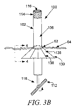
[0013] Figure 3A perspective view an embodiment of an apparatus for
implantation of an annuloplasty implant into the heart of a patient, of the
present
invention;
[0014] Figure 3B side view an embodiment of an apparatus for implantation
of an annuloplasty implant into the heart of a patient including an incision
cover, of
the present invention;
[0015] Figure 3C side view an embodiment of an apparatus for implantation
of an annuloplasty implant into the heart of a patient including an incision
cover, of
the present invention;
[0016] Figure 4 is section view of Figure 3B, illustrating the incision cover;
[0017] Figure 5A is a partial side view of an alternative embodiment of an
apparatus for implantation of an annuloplasty implant into the heart of a
patient
illustrating the assembly arms of a modified annuloplasty implant guide
assembly of
the present invention;
[0018] Figure 5B is a partial side view of an alternative embodiment of an
apparatus for implantation of an annuloplasty implant into the heart of a
patient
illustrating the assembly arms of a modified annuloplasty implant guide
assembly of
the present invention;
[0019] Figure 5C is a partial side view of an alternative embodiment of an
apparatus for implantation of an annuloplasty implant into the heart of a
patient
illustrating the assembly arms of a modified annuloplasty implant guide
assembly of
the present invention;
[0020] Figure 6A is a partial side view of another alternative embodiment of
an apparatus for implantation of an annuloplasty implant into the heart of a
patient
illustrating two piece assembly arms of a modified annuloplasty implant guide
assembly of the present invention;
[0021] Figure 6B is a partial side view of another alternative embodiment of
an apparatus for implantation of an annuloplasty implant into the heart of a
patient
illustrating two piece assembly arms of a modified annuloplasty implant guide
assembly;
[0022] Figure 6C is a partial side view of another alternative embodiment of
an apparatus for implantation of an annuloplasty implant into the heart of a
patient
illustrating two piece assembly arms of a modified annuloplasty implant guide
assembly of the present invention;
5
CA 02779605 2012-05-01
WO 2010/065912 PCT/US2009/066849
[0023] Figure 7 is a side view of another alternative embodiment of a
modified annuloplasty implant guide assembly of the present invention;
[0024] Figure 8 is a partial side view of a portion of the embodiment of the
annuloplasty implant guide assembly of illustrated in Figure 7;
[0025] Figure 9 is an illustration of the components of the MEMS motor
assembly utilized in the annuloplasty implant guide assembly illustrated in
Figure 7;
[0026] Figure 10 is a sectional view of a portion of the hook sutures of the
present invention;
[0027] Figure 11 A illustrates the interaction of an annuloplasty implant
guide assembly hook suture with an annuloplasty implant ring prior to
deployment
of the hook suture in accordance with the present invention;
[0028] Figure 11 B illustrates the interaction of an annuloplasty implant
guide assembly hook suture with an annuloplasty implant ring during deployment
of
the hook suture in accordance with the present invention;
[0029] Figure 11 C illustrates the interaction of an annuloplasty implant
guide assembly hook suture with an annuloplasty implant ring after deployment
of
the hook suture;
[0030] Figure 12 is a perspective view of another alternative embodiment of
an apparatus for implantation of an annuloplasty implant into the heart of a
patient
illustrating a modified annuloplasty implant guide assembly;
[0031] Figure 13 is a block diagram of the components driving the clamping
system of the present invention; and
[0032] Figure 14A is a clamping assembly of the present invention;
[0033] Figure 14B is a bottom view of the clamping assembly illustrated in
Figure 14A;
[0034] Figure 14C is a sectional view of a portion of the clamping assembly
illustrated in 14A;
[0035] Figure 14D is an illustration of the top clamping plate of the
clamping assembly illustrated in Figure 14A;
[0036] Figure 14E is a cross sectional view of the piston assembly of the top
clamping plate of Figure 14D;
[0037] Figure 15A is perspective view of a suturing sub assembly of the
present invention;
6
CA 02779605 2012-05-01
WO 2010/065912 PCT/US2009/066849
[0038] Figure 15B is a sectional view of the suturing sub assembly
illustrated in Figure 15A; and
[0039] Figure 15C is a sectional view of the suturing sub assembly
illustrated in Figure 15A;
GENERAL DESCRIPTION OF THE INVENTION
[0040] Various embodiments are described more fully below with reference
to the accompanying drawings, which form a part hereof, and which show
specific
embodiments of the invention. However, embodiments may be many different
forms and should not be construed as limited to the embodiments set forth
herein;
rather, these embodiments are provided so that this disclosure will be
thorough and
complete, and will fully convey the scope of the invention to those skilled in
the art.
Accordingly, the following detailed description is, therefore, not to be taken
in a
limiting sense.
[0041] The present invention describes a system and method for
implantation of generic annuloplasty rings and other surgical devices, onto a
heart
valve annulus or other anatomic orifices through minimally invasive
procedures.
More specifically, the present invention comprises an annuloplasty system and
method to repair of dysfunctional heart valve. Current standards of care for
treatment of patients with heart valve disorders require an open-heart
operation in
which the patient is put on cardiopulmonary bypass. The procedure involves
risk to
the patient's health and is associated with increased mortality. The present
invention
discloses a system and method to perform heart valve repair through a small
incision
through which an annuloplasty implant guide assembly is utilized to deliver
and
implant an annuloplasty implant within a beating heart. The annuloplasty
implant
guide assembly of the present invention discloses four sub-systems that are
configured for use in minimally invasive surgical procedures, including: (1)
an
external shape adjustment system; (2) an annuloplasty ring delivery system;
(3)
automated suturing and anchoring system; and (4) temporary adjustable annulus
system.
[0042] The external shape adjustment system is comprised of a set of trocar
devices that are used to reduce the shape of the valve annulus by applying
pressure
to the external circumference of the annular region of the heart between the
atrium
and ventricle. Upon reducing the annulus to a significantly smaller size, an
7
CA 02779605 2012-05-01
WO 2010/065912 PCT/US2009/066849
embodiment of an annuloplasty implant delivery system is used to deliver an
annuloplasty implant through a small incision and the implant is positioned
onto the
valve annulus through image guidance from a biomedical imaging modality.
[0043] The annuloplasty implant delivery system is comprised of a hollow
unitary tube, an annuloplasty implant guide assembly and a guide assembly
controller. The annuloplasty implant guide assembly, which includes a suturing
sub-assembly system is configured with a self-deployment mechanism to
facilitate
deployment of a plurality of suture hooks that connect the annuloplasty
implant to
the heart, is attached to the distal end of the unitary tube which is
comprised of a
proximal tube portion, a distal tube portion and a transition region disposed
there
between. The proximal tube portion of the unitary tube shall be configured to
include the guide assembly control mechanism which in one embodiment comprises
a pulley system having a control wire extending through the interior of the
unitary
tube and connecting to the annuloplasty implant guide assembly. The
orientation of
the annuloplasty implant guide assembly may be manipulated by the control wire
through rotation of the guide assembly control plate that is integrated into
the
annuloplasty implant guide assembly as a portion of the proximal tube portion
of the
unitary tube.
[0044] In one embodiment of the invention, the distal end of the unitary tube
includes an orientation member configured to facilitate rotation of the
annuloplasty
implant guide assembly in a manner such that its longest side is perpendicular
with
the plane of the body into which an incision has been made. This causes the
annuloplasty ring which is removably attached to the annuloplasty implant
guide
assembly to be delivered in a side-on orientation, thereby minimizing the
cross-
sectional size of the annuloplasty ring. In this embodiment, the annuloplasty
implant guide assembly has an annular shape and contains a suturing sub-
assembly
that includes a plurality of suture hooks configured to detach from the
suturing sub-
assembly and connect the annuloplasty implant ring to the annulus of a heart
valve.
In another embodiment, the annuloplasty implant guide assembly includes an
implant delivery member comprised of a plurality of arms each of which are
attached to the annuloplasty implant being delivered to the heart. The implant
delivery member is configured to facilitate folding of a flexible annuloplasty
implant
in order to facilitate passing the annuloplasty implant through an incision
having a
size smaller than necessary when the annuloplasty implant is not folded.
8
CA 02779605 2012-05-01
WO 2010/065912 PCT/US2009/066849
[00451 The attachment system of the annuloplasty implant guide assembly is
comprised of a suturing sub-assembly system including a deployment head and a
plurality of suture hooks configured to detach from the deployment head and
connect the annuloplasty implant to the heart. The attachment system also
includes
a deployment mechanism extending through the interior surface of the unitary
tube,
wherein the deployment mechanism includes at least a string that engages each
of
the plurality of suture hooks thereby hooking the annuloplasty implant
directly to
tissue within the heart through the suture hooks upon pulling the string out
through
the interior of the unitary tube. In another embodiment, the deployment
mechanism
may be automatic and contained within the implant delivery member. In one
embodiment, the plurality of suture hooks are releasably attached to the
deployment
mechanism and comprised of a first hook arm and a second hook arm, wherein the
first and second hook arms are both pivotally connected at a first end by a
pivot pin,
and the second ends of the first and second hook arms are configured to
facilitate
easy extension through tissue of an annulus wall within a heart valve and easy
extension through an annuloplasty implant thereby connecting the annuloplasty
implant to the annulus of a valve. The second ends of the first and second
hook
arms also structured to facilitate a latching connection that causes the
second ends of
the first and second hook arms to create a substantially continuous closed
loop upon
connecting the second ends of the first and second hook arms. It is
contemplated
that the annuloplasty implant guide assembly may include an adjustable
mounting
system onto which annuloplasty rings of a plurality of different shapes and
sizes
may be mounted for delivery during a minimally invasive surgical procedure.
[00461 In another embodiment, the suturing sub-assembly of the
annuloplasty implant guide assembly includes a plurality of pumps, wherein the
pumps may be microfluidic, microelectromechanical or some other pumping
configuration that facilitates pumping action at the micro level. In this
embodiment,
each of the plurality of pumps is operatively connected to at least one of the
plurality
of suture hooks and control deployment of the suture hooks which causes a
connection of the annuloplasty implant to the inner tissue of the heart cavity
into
which the annuloplasty implant is being inserted.
[0047] A plurality of microfluidic pumps position, wherein each of the
plurality of microfluidic pumps is connected to at least one of the plurality
of a
9
CA 02779605 2012-05-01
WO 2010/065912 PCT/US2009/066849
suture hooks. The microfluidic pumps control deployment and locking of the
suture
hooks onto the annuloplasty implant into position within the patient heart.
[0048] In another embodiment, the annuloplasty implant guide assembly is
configured to include an incision cover assembly. The incision cover assembly
is
attached to the exterior surface of the unitary tube and comprises umbrella
skeleton,
covered by an incision cover material, which is connected to the exterior
surface of
the unitary tube. The umbrella skeleton comprises at least a deployment ring
and
deployment arms attached thereto. Sliding the ring up and down the exterior
surface
of the unitary tube facilitates opening and closing of the incision cover.
[0049] It is contemplated that a three dimensional echocardiogram may be
used to assist a surgeon, following insertion of the delivery system through a
small
incision, in positioning an annuloplasty implant over a valve annulus during a
minimally invasive operation. Thus allowing the device to be implanted without
opening the patient's chest. Upon delivering an annuloplasty ring to the
correct
position, an automated suturing/anchoring system within the annuloplasty
implant
guide assembly is used to place permanent sutures/anchors (hooks) at multiple
locations along the circumference of the annulus, whereby hooks are deployed
directly though the ring and tissue. In one embodiment, the hooks are
comprised of
NiTinol or stainless steel. It is contemplated that the hooks may be comprised
of
any material durable enough to create hooks that hooks are deployed directly
though
the ring and tissue.
[0050] In another embodiment, the annuloplasty implant guide assembly
further is configured to include a clamping assembly that facilitates resizing
of a
valve annulus. The clamping assembly comprising a top clamp plate and a bottom
clamp plate, and a clamping assembly extending between the top clamp plate and
the bottom clamp plate that facilitates reduction of spacing between the top
clamp
plate and the bottom clamp plate.
[0051] The method of using the annuloplasty implant guide assembly to
install an annuloplasty implant involves providing an annuloplasty implant
guide
assembly configured with at least one annuloplasty implant connector to which
the
annuloplasty ring is connected. Using the guide assembly controller, the
orientation
of the implant guide assembly is adjusted, which causes adjustment of the
orientation of the annuloplasty implant in order to facilitate passing of the
annuloplasty implant through an incision on a patient's body that has a size
smaller
CA 02779605 2012-05-01
WO 2010/065912 PCT/US2009/066849
than the size required when the annuloplasty implant orientation is not
adjusted.
After extending the orientation adjusted guide assembly and the annuloplasty
ring
through the incision, the orientation of the guide assembly and thereby the
orientation of the annuloplasty ring is readjusted and the annuloplasty ring
is
positioned within a heart valve annulus. Next, an automatic suture procedure
is
initiated, wherein at least one of a plurality of suture connection hooks are
engaged
causing an end of the suture connection hook to pass through tissue of the
heart
valve annulus and the annuloplasty ring and thereby connect the annuloplasty
ring to
the heart valve annulus.
[0052] In one embodiment of this system and method, an adjustable
annuloplasty system is first temporarily implanted onto the valve annulus that
is
used to tether the annular sutures/anchors towards the anchoring hooks placed
on the
annuloplasty ring. Finally, after the valve annulus is hooked onto the
annuloplasty
rings the internal and external delivery systems are retracted out of the
patient's
body and a simple plug closure system is left in the incision to allow air
bubbles to
escape, and a zipper system is used to close the incision.
[0053] The embodiments of the present invention as shown in the
accompanying figures and described herein are particularly designed for or
relate to
the repair and replacement of atrioventricular heart valves using minimally
invasive
techniques. However, the present invention is not limited for application to
the
repair and replacement of atrioventricular heart valves, and it is
contemplated that
variations of the embodiments may apply to other heart valves and other
minimally
invasive surgical techniques.
DETAILED DESCRIPTION OF EMBODIMENTS OF THE INVENTION
[0054] Referring now to Figure 3A, 3B and 3C, the invention illustrated
comprises an adjustable apparatus 100 for implantation of an annuloplasty
implant.
The apparatus 100 is comprised of a unitary tube 102, an annuloplasty guide
assembly 112, a guide assembly controller 114 and an orientation member 118.
The
annuloplasty implant guide assembly 112 is attached to the distal end of the
unitary
tube 102 by the orientation member 118. The unitary tube 102 is comprised of a
proximal tube portion 104, a transition region 106 and a distal tube portion
108. The
unitary tube 102 is configured with an exterior surface 110 defining an
outside
11
CA 02779605 2012-05-01
WO 2010/065912 PCT/US2009/066849
diameter and an interior surface 116 defining an inside diameter of the
unitary tube
102. The proximal tube portion 104 of the unitary tube 102 includes the guide
assembly controller 114 which is operatively connected to the annuloplasty
implant
guide assembly 112 by a control mechanism that extends from the guide assembly
controller through the interior of the unitary tube 102 to the annuloplasty
implant
guide assembly 112 which includes an automatic suturing sub-assembly system
configured to deploy a plurality of suture hooks that connect the annuloplasty
implant to tissue within the heart.
[0055] Orientation member 118 which is configured to facilitate orientation
adjustment or steering of the annuloplasty implant guide assembly 112 and
thereby
orientation adjustment of an attached annuloplasty implant. The adjustment of
the
orientation or steering of annuloplasty implant guide assembly 112, as
illustrated in
Figures 3A, 3B, and 3C, occurs in response to manipulation of the guide
assembly
controller 114 and is done in order to facilitate passing the annuloplasty
implant
guide assembly 112 and the attached annuloplasty implant through an incision
62 on
a body 64 that has a size that is smaller than necessary when the implant
guide
assembly is not rotated. In situations where a straight incision has been
made,
annuloplasty implant guide assembly 112 is rotated so that it has a side-on
orientation which minimizes its cross-sectional size. After the implant guide
assembly and the annuloplasty implant have passed through the incision, the
guide
assembly controller 114 is used to readjust the orientation of the
annuloplasty
implant guide assembly 112 and the attached annuloplasty implant so that the
implant may be positioned and sutured to a heart valve annulus upon initiation
of
automatic suturing sub-assembly system.
[0056] It is contemplated that unitary tube 102 of the present invention may
comprise a unique configuration in order to perform certain aspects of the
embodiments described herein. However, some embodiments, such as the
embodiment illustrated in Figure 3A, unitary tube 102 may be a multiple lumen
catheter. As the embodiment illustrates in Figure 3A, unitary tube 102
includes an
inner cylinder 131, which in some embodiments may also be a catheter. Unitary
tube 102 also includes an incision cover assembly 130. In the embodiment of
the
apparatus 100 illustrated in Figure 3A, the inner cylinder 131 is a
translatable and
rotatable arm, one end of which is connected to the guide assembly controller
114
and the other end is connected to an umbrella skeleton deployment ring 133,
which
12
CA 02779605 2012-05-01
WO 2010/065912 PCT/US2009/066849
is connected to a frame of spars 135 within and extending through the unitary
tube
102 to connect to the umbrella skeleton 130.
[0057] Another embodiment of the incision cover assembly 130 is illustrated
in Figures 3B, 3C and 4. In this embodiment, the incision cover assembly 130
is
attached to the exterior surface of the unitary tube 102 and comprises an
umbrella
skeleton 136, covered by a biocompatible incision cover material 138. The
umbrella
skeleton 136 comprises at least a stabilizing ring 46, a deployment ring 48
and
deployment arms 50 and 52. The deployment ring 48 is configured to slide up
and
down the exterior surface of the unitary tube 20 and thereby facilitate
opening and
closing of the incision cover 30.
[0058] Referring back to Figure 3A, the proximal end 119 of the unitary tube
102 includes an opening on its distal end and allows for introduction of other
surgical implant devices through the unitary tube 102 into the body cavity.
The
distal end of the unitary tube 102 is attached to the annuloplasty implant
guide
assembly frame 120 by an orientation member 118, which provides a link between
the guide assembly controller 114 and the annuloplasty implant guide assembly
112
and includes at least a orientation bearing system 122 centrally located on
the
annuloplasty implant guide assembly frame 120 to which an annuloplasty implant
device, such as an annuloplasty ring would be attached. The annuloplasty
implant
guide assembly frame 120 is also configured with a grooved area 124 along its
circumference that facilitates positioning of an annuloplasty implant on the
guide
assembly frame 120.
[0059] The functional capabilities of apparatus 100 facilitates the process of
making a real-time incision on the outer surface of the body cavity,
introduction of a
portion of apparatus 100 into the incision 62, as illustrated in Figures 3B
and 3C,
with the assistance of sharp incision ends 126 mounted on the annuloplasty
implant
guide assembly frame 120 having a medical implant device, such as an
annuloplasty
ring mounted thereon. The incision ends 126 may be mounted on a specific
location
of the annuloplasty implant guide assembly frame 120 in order to facilitate
making
an incision of a particular dimension on the body cavity to insert the
apparatus 100.
The annuloplasty implant guide assembly 112 is rotatable by way of the
orientation
bearing system 122 which facilitates rotation of the annuloplasty implant
guide
assembly 112 and the attached annuloplasty implant in 360 degree planes with
infinite degrees of freedom as illustrated in Figure 3A, 3B, and 3C, in
response to
13
CA 02779605 2012-05-01
WO 2010/065912 PCT/US2009/066849
manipulation of the guide assembly controller 114. The ability to rotate the
annuloplasty implant guide assembly 112 and the attached annuloplasty implant
in
infinite degrees of freedom allows the user to determine the most optimal way
of
inserting the annuloplasty implant guide assembly 112 and the attached
annuloplasty
implant into the body through the smallest incision possible. Rotation can be
performed before or after insertion of the annuloplasty implant guide assembly
112
into the body cavity. Rotation of the annuloplasty implant guide assembly 112
may
be done before insertion of the annuloplasty implant guide assembly 112 into
the
body in order to reduce the size of the incision required for the annuloplasty
implant
guide assembly 112 to pass through the body. Generally, rotation of the
annuloplasty implant guide assembly 112 would be such that so that its longest
side
is perpendicular with the plane of the body into which an incision has been
made.
Figure 3C illustrates such a rotation of the annuloplasty implant guide
assembly 112.
[00601 Upon creating an incision and inserting a portion of the apparatus 100
into the body 64, the incision cover assembly 130 in deployed in order to
prevent the
loss of blood through the incision 62. Figure 3B illustrates the incision
cover
assembly 130 partially deployed. Figure 3C illustrates the incision cover
assembly
130 fully deployed. As illustrated, when the incision cover assembly 130 is
fully
deployed, it covers the incision 62 from the inside the cavity, thereby
preventing
blood loss.
[0061] The annuloplasty implant guide assembly frame 120 includes a
plurality of suture hook openings 128 around its perimeter, facilitating
deployment
of a plurality of hooks, needles or nitonol screws by a suturing sub-assembly
system
through suture hook openings 128 and thereby mounting an annuloplasty implant
ring to tissue within the heart. It is also contemplated that the annuloplasty
implant
guide-assembly frame 120 may be configured in a manner that facilitates
mounting
sutures, clips and needles directly onto the edge of the annuloplasty implant
guide
assembly frame 120. Annuloplasty implant guide assembly frame 120 is also
configured with a plurality of orifices 121 which may be used to introduce
other
sheaths, catheters, or balloon catheters into the body cavity following
introduction of
the other implantable devices through unitary tube 102. The annuloplasty
implant
guide assembly frame 120 may be of a plurality of shapes. The annuloplasty
implant guide assembly 112 may be locked into or dislodged from the unitary
tube
14
CA 02779605 2012-05-01
WO 2010/065912 PCT/US2009/066849
102 and interchanged as per the shape of the desired implant device to be
delivered
into the body cavity.
[0062] The embodiment illustrated in Figures 3A, 3B, and 3C is generally
used to insert rigid annuloplasty rings. However, because annuloplasty rings
come
in a variety forms ranging for extremely rigid to extremely flexible, an
embodiment
specifically configured for use with flexible rings was also created and is
illustrated
in Figures 5A, 5B and 5C. As illustrated in the embodiment shown in Figures
5A,
5B and 5C, the distal portion 108 of the unitary tube 102 is configured with a
modified annuloplasty implant guide assembly 140, comprised of a plurality of
assembly arms 142 each having a connector 144 that attaches to an annuloplasty
ring. The embodiment of the annuloplasty implant guide assembly 140
illustrated in
Figures 5A, 5B and 5C facilitates implantation of an annuloplasty ring through
a
much smaller incision than the incision needed when implantation is performed
by
the embodiment of the annuloplasty implant guide assembly 112 illustrated in
Figures 3A, 3B and 3C because, when the annuloplasty ring is flexible,
referring to
Figures 5A, 5B and 5C it may mounted onto connectors 144 on the distal ends of
the
plurality of assembly arms 142 and folded inward. After the annuloplasty
implant
guide assembly 140 and the distal portion 108 of the unitary tube 102 is
inserted into
the body, the guide assembly controller 114 may be manipulated and or turned,
causing the plurality of assembly arms 142 to open up in the manner
illustrated in
Figures 5B and 5C and extend to the desired position.
[0063] Another embodiment of the invention which may be used for the
insertion of flexible annuloplasty rings is illustrated in Figures 6A, 6B and
6C. In
this embodiment, the annuloplasty implant guide assembly 150 is comprised of a
plurality of assembly arms, each 152 of which comprises a top arm portion 154
and
a bottom arm portion 156 connected by a hinge pin 158 which facilitates a
hinge like
collapse or folding of each assembly arm 152 as illustrate in Figures 6A, 6B
and 6C.
As illustrated in Figures 6a, the bottom arm portion 156 may be completely
collapsed onto the top arm portion 154, or partially collapsed as illustrated
in Figure
6B, or fully extended as illustrated in Figure 6C. This configuration allows
for the
annuloplasty implant guide assembly 150 to fold an annuloplasty implant to a
size
smaller than that which may be performed by the annuloplasty implant guide
assembly 140 illustrated in Figures 5A, 5B and 5C. When implantation is
performed
by the embodiment of the apparatus illustrated in Figures 6A, 6B and 6C which
CA 02779605 2012-05-01
WO 2010/065912 PCT/US2009/066849
includes an annuloplasty implant guide assembly 150, it may mounted onto the
distal ends of each 152 of the plurality of assembly arms by connectors 160
and
folded inward. After the annuloplasty implant guide assembly 150 and the
distal
portion 108 of the unitary tube 102 is inserted into the body, the guide
assembly
controller 114 may be manipulated and or turned, causing each 152 of the
plurality
of assembly arms to open up in the manner illustrated in Figures 6B and 6C and
extend each 152 of the plurality of assembly arms to the desired position.
[0064] Figure 7 illustrates another embodiment of an annuloplasty implant
guide assembly 212, attached to the distal portion 208 of a unitary tube 202,
which
includes an orientation bearing system 222 that facilitates rotation of the
embodiment of the annuloplasty implant guide assembly 212 and the attached
annuloplasty implant ring 210 in 360 degree planes with infinite degrees of
freedom,
similar to the freedom of the annuloplasty implant guide 112 illustrated in
Figure
3A, 3B, and 3C. Annuloplasty implant guide assembly 212 rotation also occurs
in
response to manipulation of a guide assembly controller configured on the end
of the
apparatus unitary tube 202. The annuloplasty implant guide assembly 212 is
further
comprised of an annuloplasty implant guide assembly frame 220, a MEMS motor
230 attached to a motor stabilizing ring 226 by a motor stabilizing arm 234.
In this
embodiment, annuloplasty implant guide assembly frame 220 is rigid and holds
the
annuloplasty implant ring 210 in position. The motor 230 is also attached to a
suture
hook deployment arm 232 which facilitates deployment of a plurality of suture
hooks or needles, each of which is connected to a suture hook deployment arm
232
and aligned with one of a plurality of suture hook openings 224 and extends
partially
into the annuloplasty implant 210. Deploying a suture hook through one of the
plurality of suture hook openings 224 configured into the annuloplasty implant
guide assembly frame 220, causes the suture hook to also extend through the
annuloplasty implant ring 210, into tissue within the heart and then back into
the
annuloplasty implant ring 210. Deployment of a suture hook is performed by
releasing a spring temporarily attached to a portion of a suture hook.
Following
deployment of the plurality of suture hooks, the annuloplasty implant guide
assembly 212 may be removed from the incision following the release of the
annuloplasty implant ring 210 which is attached to tissue within the heart.
[0065] Figure 8 illustrates a cross sectional view of a portion of the
annuloplasty implant guide assembly 212, illustrating a suture hook deployment
arm
16
CA 02779605 2012-05-01
WO 2010/065912 PCT/US2009/066849
232, a MEMS motor 230, a motor stabilizing arm 234, a suture hook 238 and the
annuloplasty implant ring 210 which the suture hook 238 extends through. As
illustrated, the annuloplasty implant ring 210 is positioned on the guide
assembly
frame 220 and the suture hook 238 is spring loaded, wherein spring 246 has a
first
end attached 242 to a movable linear body 240 which moves linearly along
suture
hook connection arm 236. The second end of spring 246 is attached to a
connector
244 positioned on the suture hook 238. Movable linear body 240 moves linearly
along the axis of the motor as a result of the motor turning the suture hook
connection arm 236, which is screw threaded. The interior of movable linear
body
240 is also screw threaded and matingly engages the screw threads of the
suture
hook connection arm 236, thereby resulting in linear movement of the moveable
linear body 242 along the axis of the motor 230. This linear movement of the
moveable linear body 242 determines the tension in the spring 246 and thereby
the
position and turning angle of the suture hook 238. Figure 9 is an illustration
of the
MEMS motor 270 used in the embodiment illustrated in Figures 7 and 8, wherein
a
power supply 276 supplies power to the MEMS motor 270 which causes the
turnable screw threaded shaft 272 to turn, thereby initiating linear movement
of the
linear movable body based on the direction that the screw threaded shaft 272
is
turning.
[0066] Referring to Figure 10, the suture hook 238 is connected to the suture
hook connection arm 236 by a shaft 248, which slides downward instead of
linearly
through a pin opening, causing the suture hook to slide off of shaft 248,
thereby
causing automatic detachment of the suture hook and thereby completing
automatic
deployment of a plurality of suture hooks 238. The shaft 248 slides downward
following deployment of the suture hook 238, to facilitate automatic
detachment of
the suture hook 238 from the suture hook connection arm 236 and thereby
automatic
detachment of the suture hook 238 from the suturing sub-assembly system of the
apparatus 100.
[0067] Figure 11 A, 11 B, 11 C illustrates deployment of the suture hook 23 8
through the annuloplasty implant ring 210 and tissue as the suture hook 238
connects the annuloplasty implant ring 210 to tissue within the heart. Figure
11A
illustrates positioning of the suture hook 238 when the spring 246 is under
tension,
causing the suture hook 238 not to deploy. Upon the release of some of the
tension,
as illustrated in Figure 11 B, when the motor stabilizing arm 234 moves
linearly
17
CA 02779605 2012-05-01
WO 2010/065912 PCT/US2009/066849
towards the annuloplasty implant guide assembly frame 220, tension in the
spring is
released, causing the suture hook 238 to deploy through the annuloplasty
implant
ring 210 and tissue and back through the annuloplasty implant ring as a result
of the
shape of the suture hook 238 and the manner in which it pivots around the
shaft 248.
Figure 11 C illustrates full deployment of the suture hook 238 into the
annuloplasty
implant 210 following detachment of the suture hook 238 from the suture hook
connection arm 236. In the embodiment illustrated, the curvature of suture
hook 238
is such that suture hook 238 cannot go backwards and thereby hold the tissue
and the
annuloplasty implant ring 210 together.
[0068] Figure 12 is an illustration of another embodiment of the invention
which is configured in a manner to facilitate delivery of other surgical
implant
devices to a heart valve 292 following the implantation of an annuloplasty
implant
ring 290 into to a heart valve annulus by suture hooks 294. As illustrated,
other
surgical devices, such as a heart valve 286, may be delivered to the heart
valve in
need of repair through the unitary tube 280, which in other embodiments may be
a
catheter, and then connected to the annuloplasty implant ring 290. As
illustrated,
the annuloplasty implant guide assembly frame 296 remains in position
following
deployment of the suture hooks 294 connecting the annuloplasty implant ring
290
into to a heart valve annulus. The partially extended heart valve 286 is being
delivered through the unitary tube 280 of the apparatus by a partially
extended guide
wire 288 which pushes the partially extended heart valve 286 down through the
unitary tube 280, and then down into the body cavity and into the heart valve
292
where the annuloplasty implant ring 290 is implanted. Next a balloon catheter
could
be used to move the heart valve 286 into position and expand the valve 286 and
connect it with its valve arms to the annuloplasty implant ring 290 which was
previously implanted. The previously implanted the annuloplasty implant ring
290
serves as a platform that can support implantation of the secondary devices,
such as
heart valve 286, within the heart valve annulus.
[00691 As illustrated in Figure 3A, the annuloplasty implant guide assembly
frame is composed of an annular shaped tapered device. In an alternative
embodiment, the annuloplasty implant guide assembly frame may contain an
annulus clamping and suturing sub-assemblies. As was the case with the
apparatus
illustrate in Figure 3A, wherein the unitary tube 202 could be substituted for
a
catheter, the embodiments of the annuloplasty implant guide assembly frame
18
CA 02779605 2012-05-01
WO 2010/065912 PCT/US2009/066849
containing an annulus clamping and suturing sub-assemblies shall be used in
conjunction with an endoscopic catheter, currently available on the market, in
combination with a peristaltic pump system that sends pressure pulses that
manipulate the device's functions.
[0070] Referring to Figure 13, the peristaltic pump 302 will produce a
pressure that will be utilized to manipulate the mechanical parts in the
device.
Depending on the action, both negative and positive pressures will be required
to
manipulate the suturing and the clamping of the annulus. As illustrated in
Figure 13,
tubing 304 which extends through the catheter 306 will transmit pressure to
the
clamping device 310. The clamping device 310, composed of multiple pressure
channels, responds to pressure variations by miniature solenoid hydraulic
pistons
within the device. The pistons need to resist the high pressures. Tygon 2275,
manufactured by Saint-GobainTM Corporation or, preferably, silicone tubules
would
withstand the pressures transmitted to the device, and are also manufactured
for
sterility purposes. The tubing 304can be cleaned by radiation, chemicals like
ethylene oxide, or by steam, which are common methods of ensuring
sterilization for
surgical instruments.
[0071] The clamping mechanism, shown in Figures 14A, 14B and 14C, is
made up of two subassemblies: one subassembly for the top clamp 402 and a
second
subassembly for the bottom clamp 404. Clamping is used to "pinch" the native
annulus of the patient so that the suturing device is stable during suturing.
More
importantly, clamping guides the surgeon, using the echocardiogram to position
the
device properly and safely inside the heart. It is the only "visual" guide,
since the
device's dense material properties compared and the annulus- which is made of
dense fibers can be observed though imaging. A perspective view of the
clamping
mechanism 400 is shown in Figure 14A. A bottom view of the clamping
mechanism 400 is shown in Figure 14B.
[0072] The top clamping subassembly 402, as illustrated in Figure 14D
includes a mushroom like plate with rounded edges 410, a piston assembly 412,
which in this embodiment includes a piston 408 that is about 4 mm long, a
spring
418 and washer 420 attached to the piston 408. As illustrated in Figure 14E,
the
piston 408 is comprised of two parts, a top piston portion 414 and a bottom
piston
portion 416. The bottom piston portion 416 has a larger circular bottom and
begins
19
CA 02779605 2012-05-01
WO 2010/065912 PCT/US2009/066849
about at 3.5 mm from the top of the piston 408. Referring to Figure 14D, the
piston
assembly 412 is shown in a clamped down position.
[0073] As illustrated in Figure 14E, the clamping mechanism works when
fluid pressure in piston cavity 422 changes. Increased pressure from reservoir
424
causes water to flow into the piston cavity 422 through a cavity inlet 426,
which in
the present embodiment is a 0.5 mm hole on the cylindrical surface 430 of the
reservoir 424. Increased cavity pressure forces the piston 408 down, resulting
in a 3
mm displacement of the top clamp plate 410 to within 1 mm distance from the
suturing subassembly at the curved and rounded ends. The washer 420 is
permanently attached to the piston 408 to prevent the piston 408 from ejecting
off
under pressure.
[0074] Conversely, when fluid pressure in reservoir 424 is decreased, fluid
rushes off from the cavity 422, resulting in relaxation of the torsion spring
418 and
subsequent rise of the top clamp plate 410, or unclamped position of the
clamping
mechanism 400. The piston cavity 422 has a capacity of 32 mm3 when the torsion
spring 418 is stretched to maximum 3.5 height of the piston cavity 422 barrel
and a
minimum capacity of about 12.00 mm3 when piston 408 is pulled up by the
torsion
spring 418 when the torsion spring 418 is relaxed. The torsion spring 418 is
displaced by 3mm. The properties of the torsion spring were determined by the
Equation
F
where f is the flexibility of the torsion spring 418, given by displacement-
force
ratio. A torsion spring 418 of with k value of 34.0 K/m is required for the
top clamp
plate 410 of the present embodiment.
[0075] Unlike the top clamping assembly 402, the bottom clamping
assembly 404 illustrated in the present embodiment is made up of six similar
subassemblies 430, each one 3 mm below the suturing subassemblies. Because of
the general tapered shape of the inside of a right atrium within a heart, it
was
determined that the most effective way to secure the annulus in a proper
suturing
position was to stabilize the bottom of the entire device 400 by horizontally
pressing
the bottom clamps 404 to the walls of the heart just below the native annulus.
This
avoids tearing parts of the tricuspid leaflet by any actuation from the device
400. For
CA 02779605 2012-05-01
WO 2010/065912 PCT/US2009/066849
a patient with prolapsing leaflets, chances of bruising the leaflets are even
higher as
it protrudes into the atrium. The bottom clamps 404 are moved horizontally
like a
solenoid from inside of the device 400. To unclamp, the bottom clamps 404 are
retracted into the device 400.
[0076] As illustrated in Figure 14B, the larger tissue-clamping end of each of
the clamps is 6.5 mm wide, and they are all arranged in an oval shape,
mimicking
the general shape of the device and heart. The clamps extend by 3.7 mm, which
results in the expansion of the bottom part of the device by about 7 mm
diameter
(both short and long diameters). This extension, which is triggered after the
device
400 has been positioned causes stabilization of the device 400 inside the
atrium and
also aids is exposing the native annulus into the suturing subassembly.
[0077] In the embodiment illustrated, in Figure 14B, clamps 440 that are L-
shaped, are wider 442 on the outside (6.5 mm) and narrower 444 on the inside
(2.5
mm). The narrow section 444 is the piston part of the clamps that is pressed
by
increased fluid pressure from reservoir 424. The clamps 440 are spring loaded.
Increased fluid in the reservoir 424 enters the cavities that hold the clamps,
causing
extension of the clamps 440. The spring's 418 purpose is to maintain smooth
clamp
extension, and more importantly, ensure retraction of the clamp.
[0078] Referring to Figure 15A, 15B, and 15C, a suturing sub-assembly 460
is illustrated, which includes a needle 462, a silicon bed 464, and a fluid
channel 466
connected to the fluid reservoir 422 and a main reservoir 484. During
operation of
the suturing sub-assembly 460, fluid from a pump enters the suturing sub-
assembly
460 by a tubule 470 into a main reservoir 468. Increased pump reassure within
the
main reservoir 468 transmits hydrostatic pressure through fluid channel 466.
The
needle 462, which has a configuration of a C is pressed to curve around
through the
annulus into the silicone bed 464. At the silicone bed 464, the needle goes
through a
slip knot before it gets stuck. The device 400 is then unclamped and removed.
[0079] The suturing mechanism shall be comprised of a plurality of needles.
One embodiment shall be comprised of twelve needles in six subassemblies. The
geometric design of the needle 462 is configured to ensure that the needle 462
does
not curve and get driven into the adjacent subassembly. In alternative
embodiments,
individual needles may be provided per suturing subassembly.
[0080] In one embodiment, the main reservoir 468 shall include an estimated
volume of 531.06 mm3 and be connected with one inlet having a 1.5 mm diameter
21
CA 02779605 2012-05-01
WO 2010/065912 PCT/US2009/066849
tubule 470 connected to an external pump and six 0.5mm diameter channels
connected to each of the suturing units. In the suturing units, the channels
are further
subdivided into two for each, making 12 end channels, each with 0.5mm
diameter.
[0081] In one embodiment, knotted sutures are used to attach annuloplasty
implant ring to the annulus. The suture points would be the points on the
native
annulus where the needle-suture sub-assembly will act on to stitch the
artificial ring
to. To help understand the general principle behind the knotting technique
used in
the needle-suture sub-assembly a real world example will be considered. The
way
the knotting mechanism works is similar to the means by which a snare
operates. A
snare is comprised of a single piece of rope, wherein one end is looped using
a
simple slip knot. As the desired object trips the snare, the loop closes
around the
object, by drawing the rope in one direction effectively closing the loop
around the
object. The knotting mechanism operates under the same principle, wherein the
object being caught is the other end of the rope, where the needle will be
attached.
The most crucial aspect of this design is that, first the needle goes through
the loop,
and second the loop must be a sufficient size as to close in time with when
the
needle is stopped from moving in its previous direction. This is accomplished
by
making the length of the circumference of the loop the exact length the needle
shall
move from its starting position to its final destination, the silicon bed for
the
purposes of this design.
[0082] A slip knot was used to accomplish the predefined task. For the
purposes of the design the exact material considered for the suture is silk,
as it is the
most common type of suture used to perform the current surgery. The silk wire
is
approximately 0.35 mm in diameter. The needle attached to the end is slightly
curved, with a radius of curvature of 3.43mm; this specific curvature was
considered
as it allows for the needle to pass through the annulus, when the mechanism is
implemented, more easily. In addition to allowing for the needle curvature of
the
needle to help maintain the desired curved path to the final destination of
the needle.
The needle is attached to the silk wire by means of a manufacturing process
wherein
the needle is formed around, or pressed onto the silk wire effectively
affixing itself
to it. This provides for the needle not coming undone from the silk wire in
use and
the ability to apply a relatively high stress at the end of the needle without
detaching
the silk wire from the needle. The details of the construction of the needle
to the silk,
or how the silk is formed or twisted into the wire maybe found through the
22
CA 02779605 2012-05-01
WO 2010/065912 PCT/US2009/066849
manufacturer, in this case Ethicon, a division of Johnson and Johnson. Note is
it
imperative that the material chosen for the design is one that is bio-
compatible,
otherwise the body would instantly reject the material, or the probability of
infection
greatly increases.
[0083] Excess suture ends will need to be cut off from the device. While
conclusions on this will depend largely on the suture pulling mechanism, a
preliminary sliding plate has been chosen. The plate, will consist of a
sliding plate
with holes in it. Suture ends will come out of the holes. The sliding plate's
holes will
have sharp edges that would cut off the suture once slid against the
stationary plate.
Since this procedure will be performed after unclamping the device, the same
hydraulic actuator as illustrated in Figure 15 A, that is used to clamp would
be used
to create pressure that is required to slide the moveable plate.
[0084] Reference may be made throughout this specification to "one
embodiment," "an embodiment," "embodiments," "an aspect," or "aspects" meaning
that a particular described feature, structure, or characteristic may be
included in at
least one embodiment of the present invention. Thus, usage of such phrases may
refer to more than just one embodiment or aspect. In addition, the described
features, structures, or characteristics may be combined in any suitable
manner in
one or more embodiments or aspects. Furthermore, reference to a single item
may
mean a single item or a plurality of items, just as reference to a plurality
of items
may mean a single item. Moreover, use of the term "and" when incorporated into
a
list is intended to imply that all the elements of the list, a single item of
the list, or
any combination of items in the list has been contemplated.
[0085] One skilled in the relevant art may recognize, however, that the
invention may be practiced without one or more of the specific details, or
with other
methods, resources, materials, etc. In other instances, well known structures,
resources, or operations have not been shown or described in detail merely to
avoid
obscuring aspects of the invention.
[0086] While example embodiments and applications of the present
invention have been illustrated and described, it is to be understood that the
invention is not limited to the precise configuration and resources described
above.
Various modifications, changes, and variations apparent to those skilled in
the art
may be made in the arrangement, operation, and details of the methods and
systems
23
CA 02779605 2012-05-01
WO 2010/065912 PCT/US2009/066849
of the present invention disclosed herein without departing from the scope of
the
claimed invention.
[00881 The above specification, examples and data provide a description of
the manufacture and use of the invention. Since many embodiments of the
invention
can be made without departing from the spirit and scope of the invention, the
invention resides in the claims hereinafter appended.
24