Note: Descriptions are shown in the official language in which they were submitted.
CA 02779675 2016-12-21
WO 2011/054058 PCT/A U2010/001486
- 1 -
OPHTHALMIC LENS ELEMENT
This application claims priority from Australian Provisional Patent
Application
No. 2009905468 filed on 9 November 2009,
FIELD OF INVENTION
The present invention relates to ophthalmic lens elements for retarding or
arresting progression of myopia.
BACKGROUND OF THE INVENTION
To provide focussed vision, an eye must be capable of focusing light on the
retina. An eye's ability to focus light on the retina depends, to a large
extent, on the
shape of the eyeball. If an eyeball is "too long" relative to its "on-axis"
focal length
(meaning, the focal length along the optical axis of the eye), or if the
outside surface
(that is, the cornea) of the eye is too curved, the eye will be unable to
properly focus
distant objects on the retina. Similarly, an eyeball that is "too short"
relative to its on-
axis focal length, or that has an outside surface which is too flat, will be
unable to
properly focus near objects on the retina.
An eye that focuses distant objects in front of the retina is referred to as a
myopic eye. The resultant condition is referred to as myopia, and is usually
correctable
with appropriate single-vision lenses. When fitted to a wearer, conventional
single-
vision lenses correct myopia associated with central vision. Meaning that,
conventional
single-vision lenses correct myopia associated with vision that uses the fovea
and
parafovea. Central vision is often referred to as fovea' vision.
Although conventional single-vision lenses may correct myopia associated with
central vision, it is known that off-axis focal length properties of the eye
often differ from
the axial and paraxial focal lengths (Ferree et al. 1931, Arch. Ophth. 5, 717
¨ 731;
Hoogerheide et al. 1971, Ophthalmologica 163, 209 ¨ 215; Millodot 1981, Am. J.
Optom. Physiol. Opt. 58, 691 - 695). In particular, myopic eyes tend to
display less
myopia in the retina's peripheral region as compared with its foveal region.
This is often
referred to as a peripheral hyperopic shift of the image. This difference may
be due to a
myopic eye having a prolate vitreous chamber shape.
Indeed, a United States study (Mutti et al. 2000, Invest. Ophthalmol. Vis.
Sci.,
41: 1022 ¨ 1030) observed that the mean ( standard deviation) relative
peripheral
CA 02779675 2012-05-02
WO 2011/054058 PCT/AU2010/001486
- 2 -
refractions at 300 field angle in myopic eyes of children produced +0.80
1.29 D of
spherical equivalent.
Interestingly, studies with monkeys have indicated that a defocus in
peripheral
retina alone, with the fovea staying clear, can cause an elongation of the
fovea! region
(Smith et al. 2005, Invest. Ophthalmol. Vis. Sci. 46: 3965 ¨ 3972; Smith et
al. 2007,
Invest. Ophthalmol. Vis. Sci. 48, 3914 ¨ 3922) and the consequent myopia.
On the other hand, epidemiological studies have shown the presence of
correlation between myopia and near work. It is well known that the prevalence
of
myopia in the well educated population is considerably higher than that for
unskilled
labourers. Prolonged reading has been suspected of causing a hyperopic foveal
blur
due to insufficient accommodation. This has led many eye care professionals to
prescribing progressive addition or bi-focal lenses for juveniles manifesting
progression
of myopia. Special progressive lenses have been designed for use by children
(US
6,343,861). The therapeutic benefit of these lenses in clinical trials has
been shown to
be statistically significant in retarding progression of myopia but clinical
significance
appears to be limited (e.g. Hasebe et al. 2008, Invest. Ophthalmol. Vis. Sci.
49(7),
2781-2789; Yang et al. 2009, Ophthalmic Physiol. Opt. 29(1), 41-48; and
Gwiazda et
al., 2003, Invest. Ophthalmol. Vis. Sci., Vol.44, pp.1492 ¨ 1500). However,
Walker
and Mutti (2002), Optom. Vis. Sci., Vol. 79, pp.424 ¨ 430, have found that
accommodation also increases the relative peripheral refractive error,
possibly due to
the increased choroidal tension during accommodation pulling the peripheral
retina
inward.
It is believed that one trigger for myopia progression involves an eye growth
signal which compensates for hyperopic defocusing on the peripheral retina,
even in
circumstances where foveal vision is well corrected.
To correct for both foveal and peripheral vision errors at least two zones of
different lens powers are required on the same lens, namely, a central zone or
aperture
of constant minus power to correct foveal vision, and a peripheral zone of
relatively
plus power which surrounds the central zone to correct peripheral vision
errors. The
size of the central zone, the start of the peripheral zone, and the transition
between the
central zone and the peripheral zone may be varied. For example, the size of
the
central zone may be adapted according to the typical extent of habitual eye
rotation.
This may mean, for example, that the central zone may need to have a diameter
of
between about 10 mm and 20 mm on the lens surface. Typically, 0.5 D to 2.0 D
of
relatively plus power may be provided in the peripheral zone.
CA 02779675 2012-05-02
WO 2011/054058 PCT/AU2010/001486
- 3 -
One approach for providing a "power transition" between the central zone of
constant minus power and the peripheral zone of relatively plus power involves
providing an "instant" transition of the type described in international
patent publication
W02007041796. However, such a transition may present undesirable "double
vision"
type effects to a moving eye.
An alternative approach for providing a power transition between the central
zone of constant minus power and the peripheral zone of relatively plus power
involves
providing a "smooth" aspheric design which introduces a transition or
progressive
power zone between the central zone and the peripheral zone, as opposed to
providing
an "instant" power transition. For example, it is known to provide a
rotationally
symmetric transition zone. However, providing a rotationally symmetric
transition zone
may introduce a considerable amount of astigmatism which may cause undesirable
astigmatic blur on the peripheral retina.
The aspheric single vision lens described in W02007041796 corrects
peripheral hyperopic shift for both distance and near vision. However,
hyperopic blur
for distance vision typically extends over the entire width of the lens
aperture. On the
other hand, the hyperopic blur for near vision often extends over a smaller
aperture
corresponding to the angular size of the near object being viewed, such as a
book.
Also many near vision tasks, such as reading, demand a far smaller extent of
eye
rotations than those for many distance vision tasks. Therefore, one would
expect that
lenses for correcting peripheral hyperopic shift for distance vision would
have different
requirements than those for correcting peripheral hyperopic shift for near
vision, in
terms of the size of the central zone and the location and extent of the
peripheral zone.
One way of addressing the differing requirements is to provide two pairs of
lenses, one
for the distance vision requirements, the other for near vision requirements.
However
providing two pairs of lenses is often impractical.
Another approach involves providing an adapted progressive addition lens. A
progressive addition lens provides a relatively large upper viewing zone for
distance
vision tasks, a relatively narrower lower viewing zone having a different
surface power
from the upper viewing zone to achieve a refracting power corresponding to
near
vision, and an intermediate zone (or corridor) which extends between the upper
viewing zone and the lower viewing zone and provides a power progression there
between. In this respect, US 6,343,861 discloses a progressive addition lens
having a
very short power progression and a relatively large upper and lower viewing
zones for
viewing distant and near objects respectively.
CA 02779675 2012-05-02
WO 2011/054058 PCT/AU2010/001486
- 4 -
International patent publication W02008031166 discloses a progressive
addition lens having a relatively plus power in the periphery of the lens
which
corresponds with the addition power of the lower viewing zone. The lens
disclosed in
W02008031166 may introduce a myopic shift on the peripheral retina during
distance
vision tasks. However, it will not provide effective control of the location
of the
peripheral image during near vision tasks since the peripheral area of the
lower viewing
zone, at least in the immediate vicinity of the lower viewing zone, has a
lower mean
refracting power compared to the central portion of the lower viewing zone and
thus
does not provide the required relative plus power.
A recent study (Rose et al. 2008, Ophthalmology, Vol.115, Issue 8, 1279 ¨
1285) suggests that juveniles spending more time outdoors, and who, if they
are
myopes, would mostly experience peripheral hyperopic shift in an
unaccommodated
eye, show a relatively low tendency of myopia progression. It has been
suggested that
hyperopic defocus in the periphery of the retina in the presence of positive
spherical
aberration characterising a normal relaxed eye may not lead to a significant
reduction
in contrast to trigger the eye growth mechanism. Indeed, measurements and
simulations of contrast for different values and signs of defocus for a
relaxed eye by
Guo et al. (2008), Vision Res. 48, 1 804-1 81 1 show the positive (myopic)
defocus to be
more damaging to contrast on the retina than the hyperopic defocus typically
experienced in the peripheral retina by a relaxed myopic eye. It is thought
that this is
the consequence of interaction between defocus and positive spherical
aberration of
the relaxed eye. It has been suggested that spherical aberration of the eye
may provide
a cue for detecting the sign of defocus (Wilson et al. 2002, J. Opt. Soc. Am.
A 19(5),
833 ¨ 839). It is also known that the spherical aberration of the accommodated
myopic
eye becomes negative (Collins et al. 1995, Vision Res. 35(9), 1157 ¨ 1163).
This would
lead to a very different effect of hyperopic defocus on the image contrast in
near vision
compared to distance vision.
In view of the above, existing ophthalmic spectacle lenses for correcting
myopia
which provide relatively large central zones of constant power, as proposed in
WO
2007041796, may thus fail to remove stimuli for myopia progression for near
vision
tasks. It would thus be desirable to provide a progressive addition lens which
compensates for the peripheral hyperopic shift during near vision tasks while
simultaneously providing clear distance vision over a relatively wide aperture
field.
The discussion of the background to the invention herein is included to
explain
the context of the invention. This is not to be taken as an admission that any
of the
CA 02779675 2012-05-02
WO 2011/054058 PCT/AU2010/001486
- 5 -
material referred to was published, known or part of the common general
knowledge as
at the priority date of any of the claims
SUMMARY OF THE INVENTION
The present invention provides an ophthalmic lens element including an upper
viewing zone providing a first refractive power for distance vision, a lower
viewing zone
providing an addition power relative to the first refractive power, and
peripheral regions
including a respective zone of relatively positive power compared to the
addition power.
The lower viewing zone and the peripheral regions are arranged so that the
lower
viewing zone interposes the zones of relatively positive power.
Preferably, the combined horizontal extent of the zones of relatively positive
power and the lower viewing zone corresponds to a typical horizontal angular
extent of
the object field for a near object, such as a book or a magazine.
In one aspect, the present invention provides a progressive ophthalmic lens
element including:
an upper viewing zone having a distance reference point and a fitting cross,
the
upper viewing zone providing a first refractive power for distance vision;
a lower viewing zone for near vision, the lower viewing zone providing an
addition power relative to the first refractive power;
a corridor connecting the upper and lower zones, the corridor having a
refractive power varying from that of the upper viewing zone to that of the
lower viewing
zone; and
a peripheral region disposed on each side of the lower viewing zone, each
peripheral region including a zone of positive power relative to the addition
power to
provide therein a positive refractive power relative to the refractive power
of the lower
viewing zone;
wherein the zones of relative positive power are disposed immediately adjacent
to the lower viewing zone such that the lower viewing zone interposes the
zones of
relative positive power.
Preferably, the lower viewing zone is a relatively narrow zone of low surface
astigmatism. In this respect, the lower viewing zone may be defined by 0.5 D
contours
of astigmatism disposed below a near reference point. In an embodiment, the
maximum horizontal extent of the lower viewing zone, and thus the maximum
distance
between the 0.5 D contours of astigmatism, is less than about 12 mm.
CA 02779675 2012-05-02
WO 2011/054058 PCT/AU2010/001486
- 6 -
The addition power (or "Add") will typically be expressed in terms of a
desired
mean addition value. A mean addition power in the range of 0.50 D to 3.00 D
may be
used.
The zones of relatively "positive power" in the peripheral regions each
provide a
relatively positive difference in refractive power relative to the first
refractive power.
The positive difference between the refractive power in the zones of
relatively "positive
power" in the peripheral regions relative to the first refractive power is
greater than the
addition power of the lower viewing zone and thus provides a "positive power"
relative
to the addition power. Accordingly, the zones of relatively positive power may
thus also
be considered as providing an addition power which is greater than the
addition power
of the lower viewing zone.
Providing a relatively narrow lower viewing zone allows each zone of relative
positive power to be positioned in relative close proximity to a centre line
extending
substantially vertically through the lower viewing zone, and thus provide a
relatively
narrow combined horizontal extent of the zones of relatively positive power
and the
lower viewing zone. Preferably, the maximum combined horizontal extent of the
zones
of relatively positive power and the lower viewing zone is less than about 30
mm.
Embodiments of the present invention may compensate for a peripheral
hyperopic shift during near vision tasks and thus may provide an optical
correction for
retarding or arresting myopia progression for a wearer during near viewing
activities.
In some embodiments the lower viewing zone may include a near reference
point. The location of the near reference point (NRP) may be indicated using a
marking on a surface of the lens element. However, it is not essential that
the lens
element include such a marking.
Embodiments of the present invention may provide a horizontal or lateral mean
addition power profile along a horizontal line disposed below the near
reference point,
said line extending across the lower viewing zone and the peripheral regions.
The
horizontal or lateral mean addition power profile may exhibit a respective
peak
magnitude in each peripheral region and a local minimum magnitude in the lower
viewing zone. Preferably, each local minimum magnitude is disposed at the
intersection of the horizontal line and a line fitted to a set of horizontal
mid-points
between nasal and temporal 0.5 D astigmatism contours adjacent to the lower
viewing
zone. Fitting the line to the horizontal mid-points may involve suitable
approximation
techniques, such as a least squares type approximation. Other suitable
techniques
would be well understood to a skilled reader. The fitted line may be a
substantially
vertical line or it may be tilted or inclined to align with the eye-path of
the wearer.
CA 02779675 2012-05-02
WO 2011/054058 PCT/AU2010/001486
- 7 -
The respective peak magnitudes of the mean addition power may be laterally
separated from the fitted line by between about 10 mm and about 15 mm.
The first refractive power is typically a prescribed power that corresponds
with
an optical correction for a wearer's distance vision requirements. Thus, for
the
remainder of the specification, references to a "distance viewing zone" are to
be
understood as a reference to the upper viewing zone. On the other hand, the
addition
power of the lower viewing zone may be selected to ease the accommodative
demand
and shift the image plane in the periphery closer to, or in front of, the
retina during near
vision tasks. Thus, for the remainder of the specification, references to a
"near viewing
zone" are to be understood as a reference to the lower viewing zone.
The lower viewing zone will be positioned in a region of the progressive
ophthalmic lens element that is likely to be used for near vision. The lower
viewing
zone may be inset towards a nasal side of the lens relative to the distance
viewing
zone.
A progressive ophthalmic lens element according to an embodiment of the
present invention may be specifically designed for juvenile use since
juveniles typically
do not have a need for near vision correction due to the availability of the
accommodation of the eye to view objects in the near field. For example, a
juvenile
may be able to use the distance viewing zone to view near objects with the
help of their
accommodation system. However, including the lower viewing zone of addition
power
may assist juvenile wearers in reducing their accommodative demand and thus
lower
the central blur on the fovea and parafovea during near viewing tasks due to
accommodative lag. The provision of the zones of relative positive or "plus"
power
adjacent to the lower viewing zone may also reduce hyperopic blur in the
immediate
peripheral vision during near viewing tasks, such as reading, where the near
object
occupies a relatively large horizontal angular extent of the wearer's visual
field, and is
thus extended in object space. By way of example, a mobile phone's screen, for
example, would typically not occupy a large horizontal angular extent of the
wearer's
visual field, and is thus not "extended in object space" when compared to, for
example,
a book or a magazine.
Therefore, embodiments of the present invention may be more effective in
retarding or even arresting progression of myopia, particularly in children,
than prior
myopia control lenses.
The distance viewing zone of the progressive ophthalmic lens element may be
designed to be used at relatively low to moderate minus prescribed powers. It
will be
appreciated that the refracting power of the distance viewing zone may vary
according
CA 02779675 2012-05-02
WO 2011/054058 PCT/AU2010/001486
- 8 -
to a wearer's requirements, and may be in the range of, for example, plano to -
6.00 D.
A wide range of base curves may be used for this purpose, including the
relatively flat
base curves typical for minus prescriptions but also some relatively steep
base curves
that reduce the minus lens induced hyperopic shift in peripheral vision. For
example, a
base curve in the range of 0.50 D to 9.00 D may be used.
The power distribution of the zones of relatively positive power in the
peripheral
regions may contribute to an optical correction for correcting peripheral
vision, when
the wearer is viewing objects through the lower viewing zone. In use, the
power
distribution may provide a stimulus for retarding or arresting myopia in the
form of a
"stop signal" to the undesirable growth of the eye that retards or arrests
myopia
progression.
Thus, one embodiment of the present invention provides a progressive
ophthalmic lens element that provides suitable optical corrections for a
wearer's on-
axis distance vision requirements over a wide range of eye rotations, and
which is also
capable of reducing accommodative demand for near vision tasks, whilst
simultaneously providing a stop signal for retarding or arresting myopia
progression
that may otherwise have resulted from an eye's constant exposure to hyperopic
blur in
the peripheral retina during near vision.
In an embodiment, the stop signal may compensate for a varying focal plane of
the wearer's eye to remove most of the hyperopic blur from the peripheral
region of the
retina for a primary near viewing eye position. Thus, it is expected that the
distribution
of the positive power through the zones of relatively positive power in the
peripheral
regions of a progressive ophthalmic lens element in accordance with an
embodiment of
the present invention will provide an optical correction that provides the
stop signal for
undesirable ocular growth, thus leading to retardation or arresting of myopia
in the
periphery of the retina.
A progressive ophthalmic lens element according to an embodiment of the
present invention includes a front surface and a back surface (that is, the
surface
nearest the eye). The front and back surfaces may be shaped to provide
suitable
contours of refracting power and astigmatism for the upper viewing zone, the
lower
viewing zone and the corridor.
The front surface and the back surface of the lens may have any suitable
shape. In an embodiment, the front surface is an aspherical surface and the
rear
surface is spherical or toric. In another embodiment, the front surface is a
spherical
surface and the rear surface is aspherical.
CA 02779675 2012-05-02
WO 2011/054058 PCT/AU2010/001486
- 9 -
In yet another embodiment, both the front and rear surfaces are aspherical. It
will be appreciated that an aspherical surface may include, for example, an
atoric
surface, a progressive surface, or combinations thereof.
The addition power of the lower viewing zone and the relatively positive power
in the peripheral regions will typically correspond with different optical
correction
requirements of the wearer. In particular, the addition power will be selected
to provide
a near power which corresponds with an on-axial, or paraxial, optical
correction
required to provide clear vision (that is, foveal vision) for a wearer's near
vision tasks
with the reduced accommodative demand, whereas the peripheral power may
provide
an off-axis optical correction when viewing near objects through the lower
viewing
zone.
The positive mean power of each peripheral region may be selected based on
optical correction requirements expressed in terms of clinical measurements
that
characterise the wearer's peripheral correction requirements, that is, the
optical
correction required to correct a wearer's peripheral vision. Any suitable
technique may
be used to obtain those requirements including, but not limited to, peripheral
Rx data or
ultrasound A-Scan data. Such data may be obtained through the use of devices
that
are known in the art, such as an open field auto-refractor (for example, a
Shin-Nippon
open field auto-refractor).
As explained above, each peripheral region includes a zone which provides a
positive power relative to the addition power of the lower viewing zone and
thus which
also provides a zone of increased refracting power relative to the refracting
power of
the lower viewing zone. Each zone thus provides a zone of relative positive
power
which provides "a plus power correction". The positive power, and thus the
"plus power
correction" may be in the range of about 0.50 D to 2.50 D relative to the
addition power
and thus relative to the refracting power of the lower viewing zone, which
will usually be
expressed in terms of the mean refracting power at a near reference point
(NRP) of the
lens element.
As explained above, the lower viewing zone is preferably a relatively narrow
zone. In an embodiment the lower viewing zone may have a shape and/or size for
providing a region of low surface astigmatism over a range of eye-rotations
for a
wearer's near vision tasks. In other words, the near or lower viewing zone may
be
shaped and/or sized to support a wearer's near vision requirements throughout
an
angular range of eye rotations.
The area of the distance viewing zone will typically be greater than the area
of
the lower viewing zone.
CA 02779675 2016-12-21
WO 2911/054058 PCT/A
U2010/1)01486
- 10 -
A progressive ophthalmic lens element according to an embodiment of the
present invention may be formulated from any suitable material. In one
embodiment a
polymeric material may be used. The polymeric material may be of any suitable
type,
for example, it may include a thermoplastic or thermoset material. A material
of the
diallyl glycol carbonate type, for example CR-39 (PPG Industries) may be used.
The polymeric article may be formed from cross-linkable polymeric casting
compositions. The polymeric material may include a dye, preferably a
photochromic
dye, which may, for example, be added to the monomer formulation used to
produce
the polymeric material.
A progressive ophthalmic lens element according to an embodiment of the
present invention may further include standard additional coatings to the
front or back
surface, including electrochromic coatings.
The front lens surface may include an anti-reflective (AR) coating, for
example
of the type described in U.S. Pat. No. 5,704,692.
The front lens surface may include an abrasion resistant coating, for example,
of the type described in U.S. Pat. No. 4,954,591.
The front and back surfaces may further include one or more additions
conventionally used in casting compositions such as inhibitors, dyes including
thermochromic and photochromic dyes, for example, as described above,
polarising
agents, UV stabilisers and materials capable of modifying refractive index.
A preferred embodiment of a lens element according to the invention provides
an ophthalmic lens element having peripheral regions which include zones of
positive
mean power (that is, "a plus power correction") relative to the refracting
power of the
lower viewing zone.
The level of the plus power correction required by wearer will vary, given the
large scatter in the myopic peripheral refractions found by Mutti et al.
(2000).
An ophthalmic lens element according of the present invention may
simultaneously and substantially correct both central and peripheral vision
during near
vision tasks. Correction of this type is expected to remove, or at least
delay, a
presumed trigger of myopia progression in myopes, particularly in myopic
juveniles.
Another aspect of the present invention provides a method for retardation of
myopia progression, including providing to a patient spectacles bearing a pair
of
progressive ophthalmic lens elements, each lens element including a surface
having:
CA 02779675 2012-05-02
WO 2011/054058 PCT/AU2010/001486
- 11 -
an upper viewing zone having a distance reference point and a fitting cross,
the
upper viewing zone providing a first refractive power for distance vision;
a lower viewing zone for near vision, the lower viewing zone providing an
addition power relative to the first refractive power;
a corridor connecting the upper and lower zones, the corridor having a
refractive power varying from that of the upper viewing zone to that of the
lower viewing
zone; and
a peripheral region disposed on each side of the lower viewing zone, each
peripheral region including a zone of positive power relative to the addition
power to
provide therein a positive refractive power relative to the refractive power
of the lower
viewing zone;
wherein the zones of relative positive power are disposed immediately adjacent
to the lower viewing zone such that the lower viewing zone interposes the
zones of
relative positive power.
BRIEF DESCRIPTION OF THE DRAWINGS
The present invention will now be described in relation to various examples
illustrated in the accompanying drawings. However, it must be appreciated that
the
following description is not to limit the generality of the above description.
In the drawings:
Fig. 1 is a simplified representation of an ophthalmic lens element according
to
an embodiment of the present invention;
Fig. 2 is a contour plot of surface astigmatism for an ophthalmic lens element
according to a first embodiment of the present invention;
Fig. 3 is a contour plot of mean surface addition power for the ophthalmic
lens
element of Fig. 2;
Fig. 4 is a plot of mean surface addition power for the ophthalmic lens
element
of Fig. 2 along an eye path shown in Fig. 2;
Fig. 5 shows plots of mean surface addition power for the ophthalmic lens
element of Fig. 2 along plural horizontal lines shown in Fig. 3;
Fig. 6 is a contour plot of surface astigmatism for an ophthalmic lens element
according to a second embodiment of the present invention.
Fig. 7 is a contour plot of mean surface addition power for the ophthalmic
lens
element of Fig. 6;
Fig. 8 is a plot of mean surface addition power for the ophthalmic lens
element
of Fig.6 along an eye path shown in Fig. 6;
CA 02779675 2012-05-02
WO 2011/054058 PCT/AU2010/001486
- 12 -
Fig. 9 shows plots of mean surface addition power for the ophthalmic lens
element of Fig.6 along plural horizontal lines shown in Fig. 7;
Fig. 10 is a contour plot of surface astigmatism for an ophthalmic lens
element
according to a third embodiment of the present invention;
Fig. 11 is a contour plot of mean surface addition power for the ophthalmic
lens
element of Fig. 10;
Fig. 12 is a plot of mean surface addition power for the ophthalmic lens
element
of Fig. 10 along an eye path shown in Fig. 10;
Fig. 13 shows plots of mean surface addition power for the ophthalmic lens
element of Fig. 10 along plural horizontal lines shown in Fig. 11.
Fig. 14 is a contour plot of surface astigmatism for an ophthalmic lens
element
according to a fourth embodiment of the present invention;
Fig. 15 is a contour plot of mean surface addition power for the ophthalmic
lens
element of Fig. 14;
Fig. 16 is a plot of mean surface addition power for the ophthalmic lens
element
of Fig. 14 along an eye path shown in Fig. 14;
Fig. 17 shows plots of mean surface addition power for the ophthalmic lens
element of Fig. 14 along plural horizontal lines shown in Fig. 15;
Fig. 18 is a contour plot of surface astigmatism for an ophthalmic lens
element
according to a fifth embodiment of the present invention;
Fig. 19 is a contour plot of mean surface addition (digression) power for the
ophthalmic lens element of Fig. 18;
Fig. 20 is a plot of mean surface addition (digression) power for the
ophthalmic
lens element of Fig. 18 along an eye path shown in Fig. 18; and
Fig. 21 shows plots of mean surface addition (digression) power for the
ophthalmic lens element of Fig. 18 along plural horizontal lines shown in Fig.
19.
DETAILED DESCRIPTION OF THE DRAWINGS
Before turning to a description of embodiments of the present invention, there
should be some explanation of some of the language used above and throughout
the
specification.
For example, the reference in this specification to the term "progressive
ophthalmic lens element" is a reference to all forms of individual refractive
optical
bodies employed in the ophthalmic arts, including, but not limited to lenses,
lens wafers
and semi-finished lens blanks requiring further finishing to a particular
patient's
prescription.
CA 02779675 2012-05-02
WO 2011/054058 PCT/AU2010/001486
- 13 -
Further, with respect to references to the term "surface astigmatism", such
references are to be understood as a reference to a measure of the degree to
which
the curvature of the lens varies among intersecting planes which are normal to
the
surface of the lens at a point on the surface. The surface astigmatism is
equal to the
difference between the minimum and maximum curvature of the lens surface in
any of
those intersecting planes multiplied by (n-1), where n is the reference index
of
refraction.
References to the term "fitting cross" are to be understood as a reference to
a
marking located at a point on a surface of a lens element or a semifinished
lens blank,
which is stipulated by the manufacturer as a reference point for positioning
the lens
element in front of the wearer's eye.
References to the term "distance reference point" (DRP) are to be understood
as a point on the front surface of the lens at which the refractive power for
distance
vision applies.
References to the term "near reference point" (NRP) are to be understood as a
reference to the "highest" point (that is, the point most vertically displaced
in the
direction of the geometric centre of the lens) along the eye path on the front
surface of
the progressive lens where the required mean addition power can be measured.
The
NRP may be marked or designated by a marking on the surface of the lens.
However,
it is not essential that such a marking or designation be provided.
References to the term "eye path" are to be understood as a reference to a
visual fixation locus which, when the lens element is correctly designed for
the wearer,
typically coincides with a locus of horizontal mid-points between nasal and
temporal 0.5
D astigmatism contours when the wearer adjusts their fixation from a distant
(far field)
object to a close (near field) object.
References to the term "lower viewing zone" are to be understood as a
reference to a zone of low astigmatism located below the near reference point.
Typically the lower viewing zone will be defined by 0.5 D contours of
astigmatism
disposed below the near reference point.
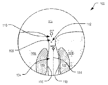
Fig. 1 depicts a simplified representation of an ophthalmic lens element 100
in
accordance with an embodiment of the present invention with the different
zones
identified for reference. Fig. 1 is simplified in as much as it is only
intended to generally
identify and represent the relative locations of the different zones of the
ophthalmic lens
element 100 using 0.5 D contours 116, 118 of astigmatism. It is to be
appreciated that
neither the shape of the different zones, nor their size or precise location,
need to be
restricted to those illustrated in Fig. 1.
CA 02779675 2012-05-02
WO 2011/054058 PCT/AU2010/001486
- 14 -
The ophthalmic lens element 100 shown in Fig. 1 includes a first or upper
viewing zone 102 having a first refractive power suitable for a wearer's
distance vision
tasks, and a second or lower viewing zone 104 providing an addition power to
the first
refractive power. A distance reference point (DRP) is provided in the upper
viewing
zone 102. A near reference point (NRP) is provided in the lower viewing zone
104.
The lens element also includes a fitting cross (FC) 110 and a geometric centre
(GC)
112.
A corridor 106 connects the upper 102 and lower 104 viewing zones. The
corridor 106 provides a zone of low surface astigmatism having a refractive
power
which varies from that of the distance viewing zone 102 to that of the lower
viewing
zone 104. In the present example the corridor extends between the distance
reference
point (DRP) and the near reference point (NRP). A line 114 (shown dashed)
extends
downwardly from the near reference point NRP. In the present case, the line
114 is a
fitted line which is fitted to horizontal mid-points between the 0.5 D nasal
and temporal
astigmatism contours 116, 118 adjacent to the lower viewing zone 104. In the
present
case the line 114 is shown as a vertical line. However, it will be appreciated
that the
line 114 may be tilted or inclined to align with the eye-path of the wearer.
The lower or near viewing zone 104 is positioned so as be suitable for a
wearer's near vision tasks. The addition power of the lower viewing zone 104
at the
near reference point (NRP) may provide a reduced accommodative demand when
viewing near objects through that zone 104. The lower viewing zone 104 may
thus
reduce accommodative demand for near vision tasks and provide an amount of
compensation for the relative hyperopic shift in the peripheral near vision.
In the illustrated embodiment, the lens element 100 also includes peripheral
regions 108 disposed on either side of the lower viewing zone 104 so as to be
located
immediately adjacent thereto. Each peripheral region 108 includes a respective
zone
120, 122 of positive power relative to the addition power of the lower viewing
zone 104.
The lower viewing zone 104 interposes the peripheral regions 108, and thus the
respective zones 120, 122 of relative positive power.
Each zone 120, 122 of relative positive power has a distribution of mean
addition power which provides an optical correction for retarding or arresting
myopia for
a wearer and which is suitable for a wearer's peripheral near vision
requirements.
Each zone 120, 122 of relative positive power will typically exhibit a low to
medium
range of positive power relative to the addition power of the lower viewing
zone 104.
Each zone of relative positive power 120,122 is disposed immediately adjacent
to lower
viewing zone 104.
CA 02779675 2012-05-02
WO 2011/054058 PCT/AU2010/001486
- 15 -
The upper viewing zone 102, the lower viewing zone 104, and the corridor 106
will typically have a relatively low surface astigmatism compared to the
surface
astigmatism of the peripheral regions 108.
The zones 120, 122 of relative positive power in the peripheral regions 108
provide a stimulus for retarding or arresting myopia associated with a
peripheral region
of the retina by providing an optical correction for the wearer's peripheral
vision. Such
an arrangement may be more effective in retarding or even arresting
progression of
myopia, particularly in children, than conventional myopia control lenses.
The positive mean power in the zones 120, 122 of relative positive power in
the
peripheral regions 108 may be selected based on optical correction
requirements
expressed in terms of clinical measurements that characterise the wearer's
peripheral
correction requirements, that is, the optical correction required to correct a
wearer's
peripheral vision. Any suitable technique may be used to obtain those
requirements
including, but not limited to, peripheral Rx data or ultrasound A-Scan data.
Such data
may be obtained through the use of devices that are known in the art, such as
an open
field auto-refractor (for example, a Shin-Nippon open field auto-refractor).
Example 1
Fig. 2 is a contour plot of surface astigmatism for the front surface (that
is, the
object side surface) of an ophthalmic lens element 200 according to an
embodiment.
Fig. 3 is a contour plot of mean surface addition power for the front surface
of the
ophthalmic lens element 200.
With reference to Fig. 2 and Fig. 3, the ophthalmic lens element 200 was
designed having a base curve of 2.75D in 1.530 index measured at the distance
reference point (DRP), shown here as located at the centre of part-circle 202.
The
geometric centre (GC) for lens element 200 is identified at point 214. The
fitting cross
(FC) is designated with a marking 206 (shown here as a cross). Semi-circle 208
is
centred on the near reference point (NRP).
The ophthalmic lens element 200 shown in Fig. 2 and Fig. 3 is a front surface
progressive addition lens having a distance reference point (DRP) located
about 8 mm
above the geometric centre (GC) 214, and a fitting cross (FC) 206 located at
about 4
mm above the geometric centre 214. The diameter of the contour plots is 60 mm
on
the lens front surface projected to a plane perpendicular to the lens front
surface
normal at the geometric centre 214.
As shown in Fig. 2, the 0.5 D astigmatic contours 210, 212 define a region of
low surface astigmatism including the upper or distance viewing zone 102, the
lower or
near viewing zone 104, and the corridor 106. The ophthalmic lens element 200
CA 02779675 2012-05-02
WO 2011/054058 PCT/AU2010/001486
- 16 -
provides a relatively wide upper viewing zone 102, and a relatively narrow
lower
viewing zone 104 positioned below the upper viewing zone 102 and connected
thereto
via the corridor 106. Peripheral regions 108 are disposed on each side of, and
immediately adjacent to, the lower viewing zone 104 so that the lower viewing
zone
104 interposes the zones of relative positive power. As will be explained
below, each
peripheral region 108 includes a zone of positive power relative to the
addition power.
The ophthalmic lens element 200 provides a nominal addition power of +1.00D
in the lower viewing zone 104 starting at a distance of about 9 mm below the
geometric
centre 214 (GC). The near reference point (NRP) is inset horizontally by about
2.1 mm
nasally relative to the geometric centre 214 (GC), the fitting cross (FC) and
the
distance reference point (DRP).
Fig. 4 is a plot of front surface addition mean power along an eye path marked
by the approximate vertical line 216 on the astigmatism contour plot shown in
Fig. 2.
In the present case, line 216 is a line fitted to horizontal mid-points
between the 0.5 D
astigmatic contours 210, 212 adjacent to the lower viewing zone 104. Note that
the
mean addition power above the distance reference point (DRP) and below the
near
reference point (NRP) is not constant so as to ensure stable optical through
power in
those zones for the prescription of -2.50 D with +1.00 D addition, the lens
back vertex
point being 27 mm from the centre of rotation of the eye and the lens
pantoscopic tilt
angle at the fitting cross being 7 relative to the vertical plane, while the
horizontal tilt
angle at the FC was equal to 00.
Fig. 5 shows the horizontal front surface mean addition power profiles for a
sequence of six straight horizontal lines 218-1, 218-2, 218-3, 218-4, 218-5,
218-6
shown (dashed) in Fig. 3 which extend 20 mm on either side of the section of
the line
216 which extends through the lower viewing zone 104, and which thus extend
across
the lower viewing zone 104 and the peripheral regions 108 of the lens element
200.
As shown in Fig. 5, along each line 218-1, 218-2, 218-3, 218-4, 218-5, 218-6
(ref. Fig. 5) the ophthalmic lens element 200 exhibits a respective mean
addition power
profile which includes a respective peak magnitude in each peripheral region
108 and a
local minimum magnitude which is disposed substantially on the line 216 (at
X=2.1
mm). Each mean addition power profile exhibits a monotonic increase in
magnitude
from the local minimum magnitude to the respective peak magnitudes.
Although in this example the sequence of straight horizontal lines 218-1, 218-
2,
218-3, 218-4, 218-5, 218-6 are located below the near reference point (NRP),
it is
possible that a similar mean addition power profile may be provided along a
horizontal
line intersecting the near reference point (NRP) and extending a predefined
distance
CA 02779675 2012-05-02
WO 2011/054058 PCT/AU2010/001486
- 17 -
across the lower viewing zone 104 and the peripheral regions 108, in which
case the
local minimum magnitude will be located at the near reference point (NRP).
The sequence of straight lines are placed vertically at 10 mm (218-1), 11 mm
(218-2), 12 mm (218-3), 13 mm (218-4), 14 mm (218-5) and 15 mm (218-6) below
the
geometric centre (GC), meaning that line 218-6 is thus located 23 mm below the
distance reference point (DRP) of the lens element 200.
As shown in Fig. 5, the respective horizontal mean addition power profiles
show
an increase in mean addition power both temporally and nasally at distances
(Y)
between -10 mm and -15 mm below the geometric centre (GC). It is also clear
from
Fig. 3 that this trend in peripheral mean power extends all the way to the
bottom of the
ophthalmic lens element 200.
At the higher end of this range (that is, Y = -10 mm, corresponding with line
218-1) the mean addition power increases by about 0.5 D (relative to the
corresponding power on the eye path represented by line 216) at the horizontal
distance of approximately 11 mm from the intersection of line 218-1 and the
fitted line
216 (ref. Fig. 2) representing the eye-path, while at the lower end of the
range (that is,
Y= -15 mm, corresponding to line 218-6) the mean addition power increases by
up to
1.25 D (relative to the corresponding power on the eye path represented by
line 216) at
the horizontal distance of approximately 14 mm from the intersection of the
line 218-6
and the fitted line 216 (ref. Fig. 2) representing the eye-path. In the
present example,
the respective peak magnitudes in mean addition power are laterally separated
by
between about 22 mm (line 218-1) and about 27 mm (line 218-6).
Example 2
Fig. 6 is a contour plot of surface astigmatism for the front surface (that
is, the
object side surface) of an ophthalmic lens element 300 according to a second
embodiment of the present invention. Fig. 7 is a contour plot of mean surface
addition
power for the front surface of the ophthalmic lens element 300 shown in Fig.
6.
The ophthalmic lens element 300 shown in Fig. 6 and Fig. 7 is also a front
surface progressive lens having the same location of the main reference points
(DRP,
FC and NRP) relative to geometric centre (GC) as the ophthalmic lens element
200 of
the above-described example.
The ophthalmic lens element 300 also has the same base curve of 2.75 D (in
1.530 index) at the distance reference point (DRP). Thus, with reference to
Fig. 6 and
Fig. 7 it is evident that the ophthalmic lens element 300 is generally similar
to the
ophthalmic lens 200 described with reference to Fig. 2 and Fig.3. For example,
the
ophthalmic lens element 200 and the ophthalmic lens element 300 each include a
CA 02779675 2012-05-02
WO 2011/054058 PCT/AU2010/001486
- 18 -
relatively short corridor 106, aspherisation of the upper 102 and lower 104
viewing
zones above the DRP 304 and below the NRP 306, and laterally increasing mean
surface power from a line 302 fitted to horizontal mid-points between the
nasal and
temporal 0.5 D astigmatism contours 21 0/21 2 adjacent to the lower viewing
zone 104.
In this example the addition power of the lower viewing zone 104 is also +1.00
D.
However, the lower viewing zone 104 of ophthalmic lens element 300 is narrower
than
the lower viewing zone 104 of ophthalmic lens element 200 with the horizontal
distance
between the peaks of relative positive or "plus" power along the line 308-6 in
Fig. 9
being around 22 mm.
Fig. 8 is a plot of front surface addition mean power along an eye path marked
by the approximate vertical line 302 on the astigmatism contour plot shown in
Fig. 6.
Fig. 9 shows the horizontal front surface mean addition power profiles for a
sequence of six straight horizontal lines 308-1, 308-2, 308-3, 308-4, 308-5,
308-6
shown (dashed) in Fig. 7 which extend 20 mm on either side of the section of
the line
302 which extends through the lower viewing zone 104, and which thus extend
across
the lower viewing zone 104 and the peripheral regions 108 of the lens element
300.
The sequence of straight lines are placed vertically at 10 mm (308-1), 11 mm
(308-2),
12 mm (308-3), 13 mm (308-4), 14 mm (308-5) and 15 mm (308-6) below the
geometric centre (GC), meaning that line 308-6 is thus located 23 mm below the
distance reference point (DRP) of the lens element 300.
Aside from the difference the width of the lower viewing zone, and with
reference now to Fig. 8 and Fig. 9, further differences from the earlier
described
example include the extent and magnitude of the relatively plus power
laterally from the
vertical mid-line 302 of the lower viewing zone 104. For example, as shown in
Fig. 9
at the height of Y = -10 mm (ref. Fig. 7, line 308-1), the maximum relative
plus power in
the peripheral regions 108 laterally occurs at around 9 mm from the eye path
represented by line 302 and with the magnitude of 0.5 D. At the lower end of
the
range at Y = -15 mm (ref. Fig. 7, line 308-6) the magnitude of the relative
positive
power is around +1.1D and occurs around 11 mm from the eye path.
The ophthalmic lens element 300 thus has the same addition power as the
previous example but includes a "tighter" zone over which peripheral near
vision has
compensation for the hyperopic shift. In other words, the lateral separation
between
the peak magnitudes in the addition power profile (ref. Fig. 9) in each
peripheral region
108 is reduced as compared with the lateral separation between the
corresponding
peak magnitudes in the addition power profile (ref. Fig. 5) for lens element
200. For
example, in lens element 300 at 15 mm (ref. Fig. 3, line 308-6) below the
geometric
CA 02779675 2012-05-02
WO 2011/054058 PCT/AU2010/001486
- 19 -
centre (GC) the lateral separation between the respective peak magnitudes in
mean
addition power is about 22 mm (ref. Fig 9, profile for line 308-6), whereas
the
corresponding respective peak magnitudes in mean addition power for lens
element
200 are laterally separated by about 27 mm (ref. Fig 5, profile 218-6). Both
ophthalmic
lens element 200 and ophthalmic lens element 300 are designed to provide the
nominal addition power in 1.6 index material.
Example 3
Fig. 10 is a contour plot of surface astigmatism for the front surface (that
is, the
object side surface) of an ophthalmic lens element 400 according to a third
embodiment of the present invention. Fig. 11 is a contour plot of mean surface
addition
power for the front surface of the ophthalmic lens element 400 shown in Fig.
6.
The ophthalmic lens element 400 shown in Fig. 10 and Fig. 11 is also a front
surface progressive lens having the same location of the main reference points
(DRP,
FC and NRP) relative to geometric centre (GC) as the ophthalmic lens element
200 of
the above-described example.
The ophthalmic lens element 400 also has the same base curve of 2.75 D (in
1.530 index) at the distance reference point 402 (DRP). Thus, with reference
to Fig. 10
and Fig. 11 it is evident that the ophthalmic lens element 400 is generally
similar to the
ophthalmic lens 200 described with reference to Fig. 2 and Fig. 3. For
example, the
ophthalmic lens element 200 and the ophthalmic lens element 400 each include a
relatively short corridor 106, aspherisation of the upper 102 and lower 104
viewing
zones above the DRP 402 and below the NRP 404, and laterally increasing mean
surface power from a line 406 fitted to horizontal mid-points between the
nasal and
temporal 0.5 D astigmatism contours 21 0/21 2 adjacent to the lower viewing
zone 104.
However, in this example the addition power of the lower viewing zone 104 is
approximately +1.50 D.
Fig. 12 is a plot of front surface addition mean power along an eye path
marked
by the approximate vertical line 406 on the astigmatism contour plot shown in
Fig.10.
Fig. 13 shows the horizontal front surface mean addition power profiles for a
sequence of six straight horizontal lines 408-1, 408-2, 408-3, 408-4, 408-5,
408-6
shown (dashed) in Fig.11 which extend 20 mm on either side of the section of
the line
406 which extends through the lower viewing zone 104, and which thus extend
across
the lower viewing zone 104 and the peripheral regions 108 of the lens element
400.
The sequence of straight lines are placed vertically at 10 mm (408-1), 11 mm
(408-2),
12 mm (408-3), 13 mm (408-4), 14 mm (408-5) and 15 mm (408-6) below the
CA 02779675 2012-05-02
WO 2011/054058 PCT/AU2010/001486
- 20 -
geometric centre (GC), meaning that line 408-6 is thus located 23 mm below the
distance reference point (DRP) of the lens element 400.
Aside from the difference in addition power, and with reference now to Fig. 12
and Fig. 13, further differences from the earlier described example include
the extent
and magnitude of the relatively plus power laterally from the vertical mid-
line 406 of the
lower viewing zone 104. For example, as shown in Fig. 9 at the height of Y = -
10 mm
(ref. Fig. 13, line 408-1), the maximum relative plus power in the peripheral
regions 108
laterally occurs at around 10 mm from the eye path and with the magnitude of
0.5 D.
At the lower end of the range at Y = -15 mm (ref. Fig. 13, line 408-2) the
magnitude of
the relative positive power is around +1.1D and occurs also around 10 mm from
the
eye path.
The ophthalmic lens element 400 thus has a relatively higher addition power
than the two earlier examples and a "tighter" zone over which peripheral near
vision
has compensation for the hyperopic shift compared to Example 1. In this
example, as
shown in Fig. 13, the lateral separation between the locations of the peak
relative
positive or "plus" power along the line 408-6 is about 21 mm compared to 27 mm
along
the corresponding line 218-6 (ref. Fig. 5) in Example 1. The addition power is
1.5 D
compared to 1.0 D in Example 1. Both ophthalmic lens element 200 and
ophthalmic
lens element 400 are designed to provide the nominal addition power in 1.6
index
material.
Example 4
Fig. 14 is a contour plot of surface astigmatism for the front surface (that
is, the
object side surface) of an ophthalmic lens element 500 according to a fourth
embodiment of the present invention. Fig. 15 is a contour plot of mean surface
addition
power for the front surface of the ophthalmic lens element 500 shown in Fig.
14.
The ophthalmic lens element 500 shown in Fig. 14 and Fig. 15 is a front
surface
progressive with a short corridor length (DRP to NRP of 17 mm, FC to NRP of 13
mm).
The ophthalmic lens element 500 has the same base curve of 2.75D in 1.530
index as
the earlier described examples. However, the ophthalmic lens element 500 shown
in
Fig. 14 and Fig. 15 provides an addition power of +2.0 D in the material index
of 1.6.
Fig. 16 is a plot of front surface addition mean power along an eye path
marked
by the approximate vertical line 506 on the astigmatism contour plot shown in
Fig.10.
Fig. 17 shows the horizontal front surface mean addition power profiles for a
sequence of six straight horizontal lines 508-1, 508-2, 508-3, 508-4, 508-5,
508-6
shown (dashed) in Fig. 15 which extend 20 mm on either side of the section of
the line
506 which extends through the lower viewing zone 104, and which thus extend
across
CA 02779675 2012-05-02
WO 2011/054058 PCT/AU2010/001486
- 21 -
the lower viewing zone 104 and the peripheral regions 108 of the lens element
500.
The sequence of straight lines are placed vertically at 10 mm (508-1), 11 mm
(508-2),
12 mm (508-3), 13 mm (508-4), 14 mm (508-5) and 15 mm (508-6) below the
geometric centre (GC), meaning that line 508-6 is thus located 23 mm below the
distance reference point (DRP) of the lens element 500.
As is shown in Fig. 17, the peak magnitude of the relatively positive power in
the peripheral regions 108, and thus the peripheral near vision plus power
compensation of this ophthalmic lens element 500, reaches up to approximately
+1.5D
on both nasal and temporal sides at Y = -15 mm (ref. Fig. 15, line 508-2) and
extends
out to around 13 mm to 14 mm on either side of the substantially vertical line
506 fitted
to horizontal mid-points between nasal and temporal 0.5 D astigmatism contours
adjacent to the lower viewing zone 104.
Example 5
The ophthalmic lens elements described in the above examples are progressive
addition lens elements having a complex surface, in the form of a progressive
power
surface, on the front (that is, the object side) of the lens elements and a
simple surface,
in the form of a spherical surface, on the rear (that is, the object side) of
the lens
element. However, it is also possible that other embodiments of the present
invention
may provide progressive addition lens elements having a progressive power
surface on
the back (that is, the eye side) of the lens element. Alternatively, optical
lens elements
according to other embodiments of the present invention may include
progressive
addition lens elements which provide a power progression split between the
front and
back surfaces with both surfaces contributing to the provision of addition
power.
Fig. 18 is a contour plot of surface astigmatism for the back surface (that
is, the
eye side surface) of an ophthalmic lens element 600 according to a fifth
embodiment of
the present invention.
Fig. 19 is a contour plot of mean surface addition power for the back surface
of
the ophthalmic lens element 600 shown in Fig. 18. In the lens element 600, the
progressive surface is disposed on the back (eye side) surface the lens
element 600,
while the front surface is spherical.
Fig. 20 is a plot of back surface addition (digression) mean power along an
eye
path marked by the approximate vertical line 606 on the astigmatism contour
plot
shown in Fig. 18.
Fig. 21 shows the horizontal back surface mean addition (digression) power
profiles for a sequence of six straight horizontal lines 608-1, 608-2, 608-3,
608-4, 608-
5, 608-6 shown (dashed) in Fig. 19 which extend 20 mm on either side of the
section of
CA 02779675 2012-05-02
WO 2011/054058 PCT/AU2010/001486
- 22 -
the line 606 which extends through the lower viewing zone 104, and which thus
extend
across the lower viewing zone 104 and the peripheral regions 108 of the lens
element
600. The sequence of straight lines are placed vertically at 10 mm (608-1), 11
mm
(608-2), 12 mm (608-3), 13 mm (608-4), 14 mm (608-5) and 15 mm (608-6) below
the
geometric centre (GC), meaning that line 608-6 is thus located 23 mm below the
distance reference point (DRP) of the lens element 600.
The lens element 600 is substantially similar to the lens element 300 (ref.
Fig.
6) described in relation to example 2, at least in terms of its optical
characteristics,
except that the location of the complex surface (that is, the progressive
surface) and
the simple surface (that is, the spherical surface) is reversed. Because the
optical
effect provided by the lens element 300 (ref. Fig. 6) and the lens element 600
is
substantially the same, in the as worn position lens element 600 and lens
element 300
may be virtually indistinguishable to the wearer and would each provide
substantially
the same addition power and relative peripheral plus power.
In this example, the ophthalmic lens element 600 has a back surface curve of
3.00 D (in 1.530 index) at the distance reference point 602 (DRP). As can be
seen in
Fig. 20, the lower viewing zone 104 of this ophthalmic lens has a power
digression on
the back (eye side) surface of the lens element 600. Such a power digression
provides
addition power when looking through the lens element 600 that has a spherical
front
surface and a complex digressive back surface.
As shown in Fig. 21, the addition power in the lower viewing zone 104 and the
relative positive or "plus" power in the peripheral regions 108 adjacent to
the lower
viewing zone 104 of this lens is substantially similar to that provided by the
lens
element 300 (ref. Fig. 6) but is achieved with a different surface
configuration. For
example, the peripheral regions 108 adjacent to the lower viewing zone 104 on
the
back surface show a relative minus surface on the back (eye side) surface of
the lens
element.
Embodiment of the present invention may provide a peripheral near vision plus
power compensation which corrects the peripheral hyperopic shift during near
vision
tasks and which thus reduces or prevents myopia progression.
Although the above embodiments have been described in terms of progressive
ophthalmic lens elements, it will be appreciated that the present invention
may also be
applicable to other forms of multi-focal lens elements, such as bifocal lens
elements.
Finally, it will be understood that there may be other variations and
modifications to the
configurations described herein that are also within the scope of the present
invention.