Note: Descriptions are shown in the official language in which they were submitted.
CA 02779864 2012-04-26
WO 2011/053879
PCT/US2010/054875
CATHETER HUB ASSEMBLY
FIELD OF THE INVENTION
100011 The invention generally relates to the field of catheters and more
particularly to a
catheter having a mechanism for retaining a distal end of the catheter in a
predetermined
configuration within a patient.
BACKGROUND OF THE INVENTION
100021 Drainage catheters may be used where fluid has collected in the body
and requires
removal. Examples include the drainage of a hematoma (collection of blood),
billoma
(collection of bile), or urinoma (collection of urine). Drainage catheters may
be used to
percutaneously drain an abscess or pocket of fluid in the body to the exterior
by means of
gravity or negative pressure. Typical abscess fluids include biliary,
nephrostomy, pleural,
urinary, and mediastinal collection.
100031 Catheterization can be used to drain the bladder after surgery or
when the
genitourinary system is plugged by an obstruction. Typically, drainage
catheters may lie in a
patient for a fairly long period of time. Accordingly, catheters have been
developed with
anchor structures to prevent inadvertent removal of the catheter from a
patient. A "pigtail
loop- as is disclosed in U.S. Patent No. 6,231,542, is one such anchor and is
formed by a
flexible tube portion at the distal end of the catheter. The pigtail loop may
be created in the
catheter by forming the flexible tube of the catheter of a memory material. A
stiff cannula or
similar implement may be inserted through the catheter lumen to straighten the
pigtail loop for
introduction into the patient. The distal end of the flexible tube returns to
the pigtail loop
configuration after the cannula is removed. Alternatively, the end of the
catheter can be
flexible and pulled into the pigtail or other anchoring configuration by
pulling a tension
member, e.g. a suture wire that extends from the distal end of the catheter to
and out of the
catheter near its proximal end. The suture wire can be attached to draw ports
located at two
separated positions along the distal portion of the catheter. Pulling the
suture juxtaposes the
draw ports and forms a pigtail loop at the distal end of the catheter. A
physician can secure the
pigtail loop by grasping and pulling on one or more suture threads that lead
distally from the
pigtail loop. When the suture thread is taut, it prevents the pigtail loop
from straightening by
holding the juxtaposed portions of the catheter together. The catheter tip can
be returned to its
straight configuration by releasing the tension of the suture at its proximal
end.
100041 With some catheters, tying or locking the suture thread prevents the
pigtail loop
1
CA 02779864 2012-04-26
WO 2011/053879
PCT/US2010/054875
from straightening. However, if the suture thread is loosened or becomes
unsecured, the pigtail
loop or other anchor at the distal end of the catheter may be released and the
catheter
inadvertently released and withdrawn from the patient.
SUMMARY OF THE INVENTION
[0005] In accordance with one embodiment provided herein, a catheter hub
assembly
comprises a hub knob and a hub body disposed within the hub knob. The hub knob
has an
exterior surface, a through lumen and a suture hole extending from the
exterior surface to the
inner lumen. The hub body has a proximal end, a distal end, and a shaft having
an exterior
surface with an inner through lumen extending between the proximal end and the
distal end. A
suture hole extending from the exterior surface of the hub body to the inner
lumen of the hub
body. The hub knob is displaceable relative to the hub body between a first
position in which
the suture holes of the hub knob and hub body are aligned and a second
position in which the
suture holes of the hub knob and hub body are offset from one another.
[0006] In accordance with another embodiment, the catheter hub assembly
includes a hub
cap that is fixed to the distal end of the hub body. The hub cap may include a
groove portion
defining first and second stops, and the hub knob may include a limit member
disposed in the
hub cap groove for engaging the hub cap first and second stops when the hub
knob is in the
first and second positions respectively.
[0007] In accordance with another embodiment, the hub body includes a
locking member
that cooperates with a locking element on the hub knob to locate the hub knob
in position
relative to the hub body.
[0008] In accordance with a further embodiment, when the hub knob is in a
first position
relative to the hub body such that the suture holes of the hub body and hub
knob are aligned,
the limit member of the hub knob engages the first stop of the hub cap to
limit displacement of
the hub knob relative to the hub body in one direction. And when the hub knob
is displaced in
the opposite direction to the second position in which the suture holes of the
hub knob and hub
body are offset, the limit member engages the second stop of the hub cap to
limit further
displacement of the hub knob relative to the hub body in one direction and the
locking member
of the hub knob engages the stop of the locking element of the hub body to
inhibit displacement
of the hub knob relative to the hub body in the opposite direction.
[0009] In accordance with another embodiment, the catheter hub assembly
includes a hub
cap that is fixed to the distal end of the hub body. The hub knob may include
a groove portion
2
CA 02779864 2013-11-26
50848-10
defining first and second stops, and the hub body may include a limit member
disposed in the
hub knob groove for engaging the hub knob first and second stops when the hub
knob is in the
first and second positions respectively.
[0010] In accordance with another embodiment, the hub knob includes a
locking
member that cooperates with a locking catch on the hub cap to locate the hub
knob in position
relative to the hub body.
[0011] In accordance with a further embodiment, when the hub knob is
in a first
position relative to the hub body such that the suture holes of the hub body
and hub knob are
aligned, the limit member of the hub body engages the first stop of the hub
knob to limit
displacement of the hub knob relative to the hub body in one direction. And
when the hub
knob is displaced in the opposite direction to the second position in which
the suture holes of
the hub knob and hub body are offset, the limit member engages the second stop
of the hub
knob to limit further displacement of the hub knob relative to the hub body in
one direction
and the locking member of the hub knob engages the locking catch of the hub
cap to inhibit
displacement of the hub knob relative to the hub body in the opposite
direction.
[0011a] In accordance with a still further embodiment, there is
provided a catheter hub
assembly comprising: a hub knob member having an outer surface, an inner
lumen, and a
suture hole extending from the outer surface of the hub knob to the inner
lumen of the hub
knob member; a hub body member disposed in the inner lumen of the hub knob
member and
including a exterior surface, an inner lumen, and a suture hole extending from
the exterior
surface of the hub body member to the inner lumen of the hub body member, the
hub knob
member being displaceable relative to the hub body member between a first
position in which
the suture holes of hub knob member and hub body member overlap and a second
position in
which the suture holes of the hub body member and hub knob member are offset
from one
another.
[0011b] In accordance with a still further embodiment, there is
provided a catheter hub
assembly comprising: a hub knob member having an outer surface, an inner
through lumen, a
suture hole extending from the outer surface of the hub knob to the inner
lumen of the hub
knob; and a locking member extending from the outer surface of the hub knob
member; a hub
3
CA 02779864 2013-11-26
50848-10
body member rotatably disposed in the inner lumen of the hub knob member and
including a
exterior surface, an inner through lumen, a suture hole extending from the
exterior surface of
the hub body member to the inner lumen of the hub body member and a locking
element
disposed on the exterior surface of the hub body member, the hub knob member
being
rotatable between a first position in which the suture holes of hub knob
member and hub body
member overlap and a second position in which the suture holes of the hub body
member and
hub knob member are offset from one another; and a hub cap member fixed to the
hub body
member, the hub cap member having an exterior surface and an inner through
lumen.
10011c] In accordance with a still further embodiment, there is
provided a catheter hub
assembly comprising: a hub knob member having an outer surface, an inner
through lumen, a
suture hole extending from the outer surface of the hub knob to the inner
lumen of the hub
knob; and a locking member extending from the inner surface of the hub knob
member; a hub
body member rotatably disposed in the inner lumen of the hub knob member and
including a
exterior surface, an inner through lumen, a suture hole extending from the
outer surface of the
hub body member to the inner lumen of the hub body member and the hub knob
member
being rotatable between a first position in which the suture holes of hub knob
member and
hub body member overlap and a second position in which the suture holes of the
hub body
member and hub knob member are offset from one another; and a hub cap member
fixed to
the hub body member, the hub cap member having an exterior surface and an
inner through
lumen, and a locking element disposed adjacent the proximal end of the hub
cap.
100121 Other systems, methods, features and advantages of the example
embodiments
will be or will become apparent to one with skill in the art upon examination
of the following
figures and detailed description.
BRIEF DESCRIPTION OF THE DRAWINGS
[0013] The details of the example embodiments, including fabrication,
structure and
operation, may be gleaned in part by study of the accompanying figures, in
which like
reference numerals refer to like parts. The components in the figures are not
necessarily to
scale, emphasis instead being placed upon illustrating the principles of the
invention.
3a
CA 02779864 2013-11-26
50848-10
Moreover, all illustrations are intended to convey concepts, where relative
sizes, shapes and
other detailed attributes may be illustrated schematically rather than
literally or precisely.
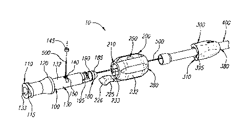
[0014] FIG. 1 is an exploded view of the catheter hub and catheter
assembly in
accordance with one embodiment;
[0015] FIG. 2 is an assembled view of the catheter hub shown in FIG. 1;
[0016] FIG. 3 is a schematic view of the hub knob and hub cap shown in
FIG. 1
assembled together;
[0017] FIG. 4 is a detailed partial exploded view of the hub body, hub
knob and hub
cap assembly shown in FIG. 1;
3b
CA 02779864 2012-04-26
WO 2011/053879
PCT/US2010/054875
[0018] FIG. 5 is an assembled view of the catheter hub assembly shown in
FIG. 1 with 0-
ring, suture wire, and catheter in the open position.
[0019] FIG. 6 is an assembled view of the catheter hub assembly shown in
FIG. 1 in the
closed position;
[0020] FIG. 7 is an exploded view of the catheter hub assembly in
accordance with another
embodiment;
[0021] FIG. 8 is a schematic of the hub body shown in FIG. 7;
[0022] FIG. 9 is a schematic view of the hub knob and hub body shown in
FIG. 7
assembled together;
[0023] FIG. 10 is a partial schematic view of the hub body shown in FIG. 7;
[0024] FIG. 11 is a schematic view of the proximal end of the hub knob
shown in FIG. 7;
[0025] FIG. 12 is a schematic view of the distal end of the hub knob shown
in FIG. 7;
[0026] FIG. 13 is a partial schematic view of the proximal end of the hub
cap shown in
FIG. 7;
[0027] FIG. 14 is an assembled view of the catheter hub and catheter
assembly shown in
FIG. 7 in a locked position.
[0028] It should be noted that elements of similar structures or functions
are generally
represented by like reference numerals for illustrative purpose throughout the
figures. It should
also be noted that the figures are only intended to facilitate the description
of the preferred
embodiments.
DETAILED DESCRIPTION
[0029] Referring to FIGS. 1-2, a catheter hub assembly 10 in accordance
with one
embodiment includes a hub body 100, a hub knob 200, and a hub cap 300. Hub
body 100 has a
proximal end 110 and a distal end 180, with a shaft 130 extending between the
proximal end
110 and the distal end 180. Shaft 130 has an exterior surface 132 and an inner
through lumen
133. The proximal end 110 of the hub body 100 may include a Luer lock 115 for
connection
with other apparatuses. The hub body 100 may include a collar 120 and a lock
element 125
located toward the proximal end 110 on the external surface 132 of the hub
body 100. In
accordance with one aspect of the invention, locking element 125 may comprise
a ramp portion
128 that increases in height along the exterior surface of the hub body 100 to
a stop portion
126.
[0030] The shaft 130 of the hub body 100 may include a recessed area 140
for receiving an
4
CA 02779864 2012-04-26
WO 2011/053879
PCT/US2010/054875
0-ring 145. A suture hole 150 is disposed in the recessed area 140 and passes
through to the
inner lumen to allow one or more suture wires 500 or tension members to pass
through. The
0-ring 145 seals the suture hole 150 to ensure that the catheter hub 10 does
not leak.
[00311 The hub body 100 may further include a flair element 185, a snap
ring 190, and an
alignment key 195 located adjacent the distal end 180 of the hub body 100. The
flair element
185 of the hub body 100 is adapted to mate with a catheter 400.
[00321 Still referring to FIGS. 1-2, the hub knob 200 has a proximal end
210, a distal end
280, an exterior surface 232 and an inner through lumen 233 into which is
received the shaft
130 of hub body 100 such that hub knob 200 is displaceable, e.g. rotatable
relative to hub body
100. Preferably, collar 120 fits over the peripheral edge of proximal end 210
of hub knob 200.
Hub knob 200 may also include a locking member 225 and a suture hole 250
extending from
the exterior surface 232 to the inner lumen 233. Preferably locking member 225
is a resilient
member that extends from the proximal end of hub knob 200 and is spring biased
toward the
exterior surface of hub shaft 130. It is also preferable that locking member
225 includes an
outwardly flared tip portion 226 that facilitates displacing the locking
member 225 in a
direction away from hub body 100. Hub knob 200 may also include a limit member
275
disposed at its distal end 280.
[00331 Referring to FIGS. 1-4, the hub cap 300 has a proximal end 310, a
distal end 380
and a through lumen 333. A groove 375 defining a first stop portion 376 and a
second stop
portion 377 may be disposed at the proximal end 310. Limit member 275 of the
hub knob 200
is received in groove 375. Hub cap 300 may also include a snap groove 390 and
an alignment
port 395. Snap ring 190 of the hub body 100 fits into a snap rut or groove 390
of the hub cap
300 to secure the hub body 100 to the hub cap 300. The distal end 380 of the
hub cap 300 is
adapted to capture the catheter 400 to be secured to the flair element 185 of
the hub body 100
when the catheter hub 10 is assembled. The exterior of the hub cap 300 can be
used to identify
the catheter French size with which it can be used. Preferably, in accordance
with one aspect
of the invention, alignment key 195 of hub body 100 is received within
alignment port 395 of
hub cap 300 to properly align hub body 100 with the hub cap 300.
[0034] Referring to FIG. 5, the catheter hub 10 is shown assembled and
attached to a
catheter 400 with the hub knob 200 being disposed in a first open position in
which the suture
holes 250 and 150 are aligned with one another. Preferably, locking member 225
is disposed in
a first position overlying ramp portion 128 and out of engagement with stop
portion 126. It is
CA 02779864 2012-04-26
WO 2011/053879
PCT/US2010/054875
also preferable that in this first open position, limit member 275 engages
stop 376 (see FIG. 3)
to prevent further rotation of hub knob in a counterclockwise direction. In
this open position,
suture wire 500 is freely moveable through the suture holes 250 and 150 and
can be readily
pulled out of hub knob 200 which effects the pulling of the flexible end 426
of catheter 400
into the pigtail configuration shown in FIG. 6. Further referring to FIG. 6
and FIG. 2, hub knob
200 may be rotated in a clockwise direction until locking member 225 traverses
ramp position
128 of locking element 125 and because of its spring bias snaps into
engagement with stop
portion 126 of locking element 125. Stop 126 limits counter-rotation of hub
knob 200 in the
clockwise direction.
100351 Referring to FIG. 6, this second position of hub knob 200 is a
locked position
because suture holes 250 and 150 are now offset relative to one another and
suture wire 500 is
trapped between the inside surface of hub knob 200 and the outside surface of
hub body 100.
This trapping or locking of suture wire 500, effectively keeps suture wire
stationary so as to
maintain the catheter end 426 in position, e.g., in the pigtail configuration
of FIG. 6.
Preferably, in this closed position, limit member 375 also engages stop 377 to
prevent further
rotation of hub knob 200 in a clockwise direction. To unlock the assembly, a
user can pull
back resilient locking member 225 to raise it over stop 126 so as to disengage
it from stop 126.
Hub knob 200 can then be rotated in a clockwise direction such that locking
member 225
engages the ramp portion of 128 locking element 125 to the open position where
suture holes
250 and 150 are again aligned and suture wire can be readily moved and the
catheter pigtail
configuration straightened out so that the catheter can be removed from the
patient.
[0036] Referring to FIGS. 7-8, a catheter hub assembly 1010 in accordance
with another
embodiment includes a hub body 1100, a hub knob 1200, and a hub cap 1300. Hub
body 1100
has a proximal end 1110 and a distal end 1180, with a shaft 1130 extending
between the
proximal end 1110 and the distal end 1180. Shaft 1130 has an exterior surface
1132 and an
inner through lumen 1133. The proximal end 1110 of the hub body 1100 may
include a Luer
lock 1115 for connection with other apparatuses. The hub body 1100 may include
a collar
1120.
[0037] The shaft 1130 of the hub body 1100 may include a recessed area 1140
for receiving
an 0-ring. A suture hole 1150 is disposed in the recessed area 1140 extending
to the inner
lumen 1133 to allow one or more suture wires to pass through. The 0-ring seals
the suture
hole 1150 to ensure that the catheter hub 1010 does not leak.
6
CA 02779864 2012-04-26
WO 2011/053879
PCT/US2010/054875
[0038] The hub body 1100 may further include a flair element 1185 and a
snap ring 1190
located adjacent the distal end 1180 of the hub body 1100, and an alignment
keyway 1195
extending from adjacent the distal end 1180 of the hub body 1100
longitudinally along the
outer surface 1132 of the hub body 1100 toward the proximal end 1110. The
flair element
1185 of the hub body 1100 is adapted to mate with a catheter. Opposing
recesses 1176 and
1177 are formed along the exterior surface 1132 of the hub body 1100
increasing in depth as
they extend toward the proximal end 1110 of the hub body 1100.
[00391 Referring to FIGS. 7-11, the hub knob 1200 has a proximal end 1210,
a distal end
1280, an exterior surface 1232 and an inner through lumen 1233 into which is
received the
shaft 1130 of hub body 1100 such that hub knob 1200 is displaceable, e.g.
rotatable relative to
hub body 1100. Preferably, collar 1120 fits within the proximal end 1210 of
the hub knob
abutting arcuate stop 1278 such that the proximal face of the collar 1120 is
flush with the
peripheral edge of proximal end 1210 of hub knob 1200. Hub knob 1200 may also
include a
suture hole 1250 extending from the exterior surface 1232 to inner lumen 1233.
A groove 1275
defining a first stop portion 1276 and a second stop portion 1277 may be
disposed internally
adjacent the proximal end 1210 of the hub knob 1200. Limit member 1125
extending from the
collar 1120 of the hub body 1100 is received in groove 1275 and engages stop
portions 1276 or
1277 to limit rotation of the hub knob 1200.
[0040] Referring to FIGS. 7-13, hub cap 1300 has a proximal end 1310, a
distal end 1380
and an inner through lumen 1333. Hub cap 1300 may also include a snap groove
along the
inner through lumen 1333 adjacent the distal end 1310 and an alignment key
1395 extending
along the inner through lumen 1333. Preferably, the alignment key 1395 of hub
cap 1300 is
received within alignment keyway 1195 of hub body 1100 to properly align the
hub body 1100
with hub cap 1300. Snap ring 1190 of the hub body 1100 fits into the snap
groove (see, e.g.,
390 in FIG. 4) of the hub cap 1300 to secure the hub body 1100 to the hub cap
1300. The distal
end 1380 of the hub cap 1300 is adapted to capture a catheter to be secured to
the flair element
1185 of the hub body 1100 when the catheter hub 1010 is assembled. The
exterior surface
1332 of the hub cap 1300 may have a depression 1302 that can be used to
identify the catheter
French size of the device.
100411 Preferably the proximal end 1310 of the hub cap 1300 is divided into
two opposing
resilient members 1360 and two opposing non-resilient members 1370 with
adjacent resilient
and non-resilient members 1360 and 1370 being in spaced relation with gaps
1372 extending
7
CA 02779864 2012-04-26
WO 2011/053879
PCT/US2010/054875
longitudinally between members 1360 and 1370. The resilient members 1360 are
outwardly
spring biased. Catch or locking members 1362 preferably extend proximally from
resilient
members 1360. The catch members 1362 have a first ramped or arcuate forward
surface 1363,
a second ramped or arcuate rear surface 1365 and a recessed catch 1364 formed
there between.
Catch tabs 1260 formed on the interior of the hub knob 1200 cooperate with the
catch members
1362 to positively position the hub knob 1200 in the locked and unlocked
positions. As the
hub knob 1200 is rotated toward the locked position, the catch tabs 1260
engage the ramped
surface 1363 of the catch members 1362 deflecting the resilient members 1360
inward toward
the hub shaft 1130. When the catch tabs 1260 reach the recessed catches 1364,
the resilient
members 1360 because of their spring bias spring outward toward the hub knob
1200 giving a
snap like feel to the positioning of the hub knob 1200 in the locked position.
Further rotation
of the hub knob 1200 is prevented by one of the stop portions 1276 or 1277
defined by the
groove 1275 in the hub knob 1200 and the limit member 1125 of the hub body
1100.
[0042] To release the hub knob 1200 and rotate it from a locked position to
an unlocked
position, buttons 1366 formed on the exterior of the resilient members 1360
are pressed to
deflect the resilient members 1360 inward and release the catch tabs 1260 from
the recessed
catches 1364. As the hub knob 1200 is rotated toward the unlocked position,
the catch tabs
1260 engage the second ramped surface 1365 of the catch members 1362
deflecting the
resilient members 1360 inward toward the hub shaft 1130. When the catch tabs
1260 reach the
recessed catches 1364, the resilient members 1360 move outward toward the hub
knob 1200 to
positively position the hub knob 1200 in the unlocked position. Further
rotation of the hub
knob 1200 is prevented by one of the stop portions 1276 or 1277 defined by the
groove 1275 in
the hub knob 1200 and the limit member 1125 of the hub body 1100.
[0043] Preferably, the recessed catch 1364 has a first surface 1367 that
acts as a stop to
prevent rotation of the hub knob 1200 from the locked to the unlocked position
without
deflecting the resilient members 1360 inward, and a ramped surface 1368 that
the catch tabs
1260 engage to deflect the resilient members 1360 inward to allow the hub knob
1200 to rotate
from the unlocked position to the locked position.
[0044] Referring to FIG. 14, the catheter hub assembly 1010 is shown with
the hub knob
1200 being disposed in a locked position in which the suture holes 1250 and
1150 offset from
one another. As a result, the suture wire 500 is locked in place between the
hub knob 1200 and
the hub body 1100 extending between suture holes 1250 and 1150 which effects
holding the
8
CA 02779864 2012-04-26
WO 2011/053879
PCT/US2010/054875
flexible end of catheter 1400 into a pigtail configuration.
[0045] It will be apparent to those skilled in the art that various
modifications and
variations can be made in the apparatus and method of the present invention
without departing
from the spirit or scope of the invention. Thus, it is intended that the
present invention cover
the modifications and variations of this invention provided they come within
the scope of the
appended claims and their equivalents.
9