Note: Descriptions are shown in the official language in which they were submitted.
CA 02779964 2012-05-03
OPEN-HOLE PACKER FOR ALTERNATE PATH GRAVEL PACKING,
AND METHOD FOR COMPLETING AN OPEN-HOLE WELLBORE
BACKGROUND OF THE INVENTION
=
[0002] This
section is intended to introduce various aspects of the art, which may
be associated with exemplary embodiments of the present disclosure. This
discussion is believed to assist in providing a framework to facilitate a
better
understanding of particular aspects of the present disclosure. Accordingly, it
should
be understood that this section should be read in this light, and not
necessarily as
admissions of prior art.
Field of the Invention
[0oo] The
present disclosure relates to the field of well completion. More
specifically, the preserit invention relates to the isolation of formations in
connections
with wellbores that have been completed using gravel-packing.
Discussion of Technology
[mu] In
the drilling of oil and gas wells, a wellbore is formed using a drill bit that
is urged downwardly at a lower end of a drill string. After drilling to a
predetermined
depth, the drill string and bit are removed and the wellbore is lined with a
string of
casing. An annular area is thus formed between the string of casing and the
formation. A cementing operation is typically conducted in order to fill or
"squeeze"
the annular area with cement. The combination of cement and casing strengthens
the wellbore and facilitates the isolation of certain areas of the formation
behind the
casing.
[0005] It is
common to place several strings of casing having progressively
smaller outer diameters into the wellbore. Thus, the process of drilling and
then
cementing progressively smaller strings of casing is repeated several times
until the
well has reached total depth. The final string of casing, referred to as a
production
casing, is cemented into place. In some instances, the final string of casing
is a
liner, that is, a string of casing that is not tied back to the surface.
- 1 -
CA 02779964 2012-05-03
WO 2011/062669 PCT/US2010/046329
[0006] As part of the completion process, a wellhead is installed at the
surface.
Fluid gathering and processing equipment such as pipes, valves and separators
are
also provided. Production operations may then commence.
[0007] In connection with the production of non-condensable
hydrocarbons, water
may sometimes invade the formation. This may be due to the presence of native
water zones, coning (rise of near-well hydrocarbon-water contact), high
permeability
streaks, natural fractures, and fingering from injection wells. Depending on
the
mechanism or cause of the water production, the water may be produced at
different
locations and times during a well's lifetime. In addition, undesirable
condensable
fluids such as hydrogen sulfide gas or acid gases may invade a formation.
[0oos] Many completed wells include multiple zones in one more intervals
that
may be of extended lengths. During operation of wells having multiple zones,
it is
desirable to control and manage fluids produced from different zones. For
example,
in production operations, proper control of the fluid production rates in
various zones
can delay water or gas coning, helping to maximize reserve recovery.
[0009] Various techniques are known to determine whether zonal isolation
will be
effective or desirable for preventing the production of water or unwanted gas,
and
where in a well to position the zonal isolation. Exemplary implementations of
zonal
isolations and inflow control devices installed in wells have been documented
in
various publications, including M.W. Helmy, et al., "Application of New
Technology in
the Completion of ERD Wells, Sakhalin-1 Development," SPE Paper No. 103587
(October 2006); and David C. Haeberle, et al., "Application of Flow-Control
Devices
for Water Injection in the Erha Field", SPE Paper No. 112726 (March 2008).
Careful
installation of zonal isolation in the initial completion allows an operator
to shut-off
the production from one or more zones during the well lifetime to limit the
production
of water or, in some instances, an undesirable condensable fluid such as
hydrogen
sulfide.
[0olo] Open-hole completions are oftentimes employed when multiple zones
are
sought to be produced. In open-hole completions, a production casing is not
extended through the producing zones and perforated; rather, the producing
zones
are left uncased, or "open." A production string or "tubing" is then
positioned inside
the wellbore extending down below the last string of casing and across the
formations of interest.
- 2 -
CA 02779964 2012-05-03
WO 2011/062669 PCT/US2010/046329
[0011] There are certain advantages to open-hole completions versus
cased hole
completions. First, because open-hole completions have no perforation tunnels,
formation fluids can converge on the wellbore radially 360 degrees. This has
the
benefit of eliminating the additional pressure drop associated with converging
radial
flow and then linear flow through particle-filled perforation tunnels. The
reduced
pressure drop associated with an open-hole sand control completion virtually
guarantees that it will be more productive than an unstimulated, cased hole in
the
same formation.
[0012] Second, open-hole gravel pack techniques are oftentimes less
expensive
than cased hole completions. For example, the use of gravel packs eliminates
the
need for cementing, perforating, and post-perforation clean-up operations. In
some
cases, the use of extended gravel packs avoids the need for an additional
casing
string or liner.
[0013] A common problem in open-hole completions is the immediate
exposure
of the wellbore to the surrounding formation. If the formation is
unconsolidated or
heavily sandy, the flow of production fluids into the wellbore may carry with
it
formation particles, e.g., sand and fines. Such particles can be erosive to
production
equipment downhole and to pipes, valves and separation equipment at the
surface.
[0014] To control the invasion of sand and other particles, sand control
devices
may be employed. Sand control devices are usually installed downhole across
formations to retain solid materials larger than a certain diameter while
allowing
fluids to be produced. The sand control device is typically an elongated
tubular
body, known as a base pipe, having numerous slotted openings. The base pipe is
typically wrapped with a filtration medium such as a screen or wire mesh.
[0015] To augment the sand control devices, particularly in open-hole
completions, it is common to install a gravel pack. Gravel packing a well
involves
placing gravel or other particulate matter around the sand control device
after the
sand control device is hung or otherwise placed in the wellbore. The gravel
not only
aids in particle filtration but also maintains formation integrity. Thus, in
such an
open-hole completion, the gravel is positioned between the wall of the
wellbore and
a sand screen that surrounds a perforated base pipe. Formation fluids flow
from the
subterranean formation into the production string through the gravel, the
screen, and
the inner base pipe.
- 3 -
CA 02779964 2012-05-03
[0016] In
connection with the installation of a gravel pack, a particulate material is
delivered downhole by means of a carrier fluid. The carrier fluid with the
gravel
together forms a gravel slurry. A problem historically encountered with gravel-
packing is that an inadvertent loss of carrier fluid from the slurry during
the delivery
process can result in sand or gravel bridges being formed at various locations
along
open-hole intervals. For example, in an inclined production interval or an
interval
having an enlarged or irregular borehole, a poor distribution of gravel may
occur due
to a premature loss of carrier fluid from the gravel slurry into the
formation. The fluid
loss may then cause voids to form in the gravel pack. Thus, a complete gravel-
pack
from bottom to top is not achieved.
[0017]
Relatively recently, this problem has been addressed through the use of
alternate path technology. Alternate path technology employs shunts that allow
the
gravel slurry to bypass selected areas along a wellbore. Such alternate path
technology is described at least in PCT Publication No. WO 2008/060479, and
M.D.
Barry, et al., "Open-hole Gravel Packing with Zonal Isolation," SPE Paper No.
110460
(November 2007).
[0018] Zonal
isolation in open-hole completions is desirable for establishing and
maintaining optimized long-term performance of both injection and production
wells.
This ideally involves the placement and setting of packers before gravel
packing
commences. The packers would allow the operator to seal off an interval from
either
production or injection, depending on well function. However, packers
historically
have not been installed when an open-hole gravel pack is utilized because it
is not
possible to form a complete gravel pack above and below the packer.
[0019] PCT Publication Nos. WO 2007/092082 and WO 2007/092083 disclose
apparatus' and methods for gravel-packing an open-hole wellbore after a packer
has
been set at a completion interval. These applications further disclose how
zonal
isolation in open-hole, gravel-packed completions may be provided by using a
conventional packer element and secondary (or "alternate") flow paths to
enable
both zonal isolation and alternate path gravel packing.
[0020]
Certain technical challenges exist with respect to the methods disclosed in
the incorporated PCT publications, particularly in connection with the packer.
The
- 4 -
CA 02779964 2012-05-03
WO 2011/062669 PCT/US2010/046329
applications state that the packer may be a hydraulically actuated inflatable
element.
Such an inflatable element may be fabricated from an elastomeric material or a
thermoplastic material. However, designing a packer element from such
materials
requires the packer element to meet a particularly high performance level. In
this
respect, the packer element needs to be able to maintain zonal isolation for a
period
of years in the presence of high pressures and/or high temperatures and/or
acidic
fluids. As an alternative, the applications state that the packer may be a
swelling
rubber element that expands in the presence of hydrocarbons, water, or other
stimulus. However, known swelling elastomers typically require about 30 days
or
longer to fully expand into sealed fluid engagement with the surrounding rock
formation.
[0021] Therefore, what is needed is an improved sand control system that
provides not only alternate flow path technology for the placement of gravel
around a
packer, but also an improved packer assembly for zonal isolation in an open-
hole
completion. Improved methods are also needed for isolating selected intervals
of a
subsurface formation in an open-hole wellbore.
SUMMARY OF THE INVENTION
[0022] A gravel pack zonal isolation apparatus for a wellbore is
provided herein.
The zonal isolation apparatus has utility in connection with the placement of
a gravel
pack within an open-hole portion of the wellbore. The open-hole portion
extends
through one, two, or more subsurface intervals.
[0023] In one embodiment, the zonal isolation apparatus includes an
elongated
base pipe. The base pipe defines a tubular member having an upper end and a
lower end. Preferably, the zonal isolation apparatus further comprises a
filter
medium surrounding the base pipe along a substantial portion of the base pipe.
Together, the base pipe and the filter medium form a sand screen.
[0024] The zonal isolation apparatus also includes at least one and,
more
preferably, at least two packer assemblies. Each packer assembly comprises at
least two mechanically set packer elements. These represent an upper packer
and
a lower packer. The upper and lower packers preferably comprise mechanically
set
packer elements that are about 6 inches to 24 inches in length.
[0025] Intermediate the at least two mechanically set packer elements is
at least
one swellable packer element. The swellable packer element is preferably about
3
feet to 40 feet in length. In one aspect, the swellable packer element is
fabricated
- 5 -
CA 02779964 2012-05-03
WO 2011/062669 PCT/US2010/046329
from an elastomeric material. The swellable packer element is actuated over
time in
the presence of a fluid such as water, gas, oil, or a chemical. Swelling may
take
place, for example, should one of the mechanically set packer elements fails.
Alternatively, swelling may take place over time as fluids in the formation
surrounding the swellable packer element contact the swellable packer element.
[0026] The swellable packer element preferably swells in the presence of
an
aqueous fluid. In one aspect, the swellable packer element may include an
elastomeric material that swells in the presence of hydrocarbon liquids or an
actuating chemical. This may be in lieu of or in addition to an elastomeric
material
that swells in the presence of an aqueous fluid.
[0027] In one aspect, the elongated base pipe comprises multiple joints
of pipe
connected end-to-end. The gravel pack zonal isolation apparatus may include an
upper packer assembly and a lower packer assembly placed along the joints of
pipe.
The upper packer assembly and the lower packer assembly can be spaced apart
along the joints of pipe so as to isolate a selected subsurface interval
within a
wellbore.
[0028] The zonal isolation apparatus also includes one or more alternate
flow
channels. The alternate flow channels are disposed outside of the base pipe
and
along the various packer elements within each packer assembly. The alternate
flow
channels serve to divert gravel pack slurry from an upper interval to one or
more
lower intervals during a gravel packing operation.
[0029] A method for completing an open-hole wellbore is also provided
herein. In
one aspect, the method includes running a gravel pack zonal isolation
apparatus into
the wellbore. The wellbore includes a lower portion completed as an open-hole.
The zonal isolation apparatus is in accordance with the zonal isolation
apparatus
described above.
[0030] Next, the zonal isolation apparatus is hung in the wellbore. The
apparatus
is positioned such that the at least one packer assembly is positioned
essentially
between production intervals of the open-hole portion of the wellbore. Then,
the
mechanically set packers in each of the at least one packer assembly are set.
[0031] The method also includes injecting a particulate slurry into an
annular
region formed between the sand screen and the surrounding subsurface
formation.
The particulate slurry is made up of a carrier fluid and sand (and/or other)
particles.
The one or more alternate flow channels of the zonal isolation apparatus allow
the
- 6 -
CA 02779964 2012-05-03
WO 2011/062669 PCT/US2010/046329
particulate slurry to travel through or around the mechanically set packer
elements
and the intermediate swellable packer element. In this way, the open-hole
portion of
the wellbore is gravel packed above and below (but not between) the
mechanically
set packer elements.
[0032] The method also includes producing production fluids from one or
more
production intervals along the open-hole portion of the wellbore, or injecting
injection
fluids into the open-hole portion of the wellbore. Production or injection
takes place
for a period of time. Over the period of time, the upper packer, the lower
packer, or
both, may fail, permitting the inflow of fluids into an intermediate portion
of the packer
along the swellable packer element. Alternatively, the intermediate swellable
packer
may swell due to contact with formation fluids or an actuating chemical.
Contact with
fluids will cause the swellable packer element to swell, thereby providing a
long term
seal beyond the life of the mechanically set packers.
BRIEF DESCRIPTION OF THE DRAWINGS
[0033] So that the manner in which the present inventions can be better
understood, certain illustrations, charts and/or flow charts are appended
hereto. It is
to be noted, however, that the drawings illustrate only selected embodiments
of the
inventions and are therefore not to be considered limiting of scope, for the
inventions
may admit to other equally effective embodiments and applications.
[0034] Figure 1 is a cross-sectional view of an illustrative wellbore. The
wellbore
has been drilled through three different subsurface intervals, each interval
being
under formation pressure and containing fluids.
[0035] Figure 2 is an enlarged cross-sectional view of an open-hole completion
of the
wellbore of Figure 1. The open-hole completion at the depth of the three
intervals is
more clearly seen.
[0036] Figures 3A to 3D present an illustrative packer assembly as may
be used
in the present inventions, in one embodiment. The packer assembly employs
individual shunt tubes to provide an alternative flowpath for a particulate
slurry.
[0037] Figures 4A to 4D provide an illustrative packer assembly as may
be used
in the zonal isolation apparatus and in the methods herein, in an alternate
embodiment.
[0038] Figures 5A through 5N present stages of a gravel packing
procedure using
one of the packer assemblies of the present invention, in one embodiment, and
- 7 -
CA 02779964 2012-05-03
WO 2011/062669 PCT/US2010/046329
using alternative flowpath channels through the packer elements of the packer
assembly and through the sand control devices.
[0039] Figure 50 shows a packer assembly and gravel pack having been set
in
an open hole wellbore following completion of the gravel packing procedure
from
Figures 5A through 5N.
[0040] Figure 6A is a cross-sectional view of a middle interval of the
open-hole
completion of Figure 2. Here, a straddle packer has been placed within a sand
control device across the middle interval to prevent the inflow of formation
fluids.
[0041] Figure 6B is a cross-sectional view of middle and lower intervals
of the
open-hole completion of Figure 2. Here, a plug has been placed within a packer
assembly between the middle and lower intervals to prevent the flow of
formation
fluids up the wellbore from the lower interval.
[0042] Figure 7 is a flowchart showing steps that may be performed in
connection
with a method for completing an open-hole wellbore.
DETAILED DESCRIPTION OF CERTAIN EMBODIMENTS
Defin itions
[0043] As used herein, the term "hydrocarbon" refers to an organic
compound
that includes primarily, if not exclusively, the elements hydrogen and carbon.
Hydrocarbons generally fall into two classes: aliphatic, or straight chain
hydrocarbons, and cyclic, or closed ring hydrocarbons, including cyclic
terpenes.
Examples of hydrocarbon-containing materials include any form of natural gas,
oil,
coal, and bitumen that can be used as a fuel or upgraded into a fuel.
[0044] As used herein, the term "hydrocarbon fluids" refers to a
hydrocarbon or
mixtures of hydrocarbons that are gases or liquids. For example, hydrocarbon
fluids
may include a hydrocarbon or mixtures of hydrocarbons that are gases or
liquids at
formation conditions, at processing conditions or at ambient conditions (15 C
and 1
atm pressure). Hydrocarbon fluids may include, for example, oil, natural gas,
coal
bed methane, shale oil, pyrolysis oil, pyrolysis gas, a pyrolysis product of
coal, and
other hydrocarbons that are in a gaseous or liquid state.
[0045] As used herein, the term "fluid" refers to gases, liquids, and
combinations
of gases and liquids, as well as to combinations of gases and solids, and
combinations of liquids and solids.
[0046] As used herein, the term "condensable hydrocarbons" means those
hydrocarbons that condense at about 15 C and one atmosphere absolute
pressure.
- 8 -
CA 02779964 2012-05-03
WO 2011/062669 PCT/US2010/046329
Condensable hydrocarbons may include, for example, a mixture of hydrocarbons
having carbon numbers greater than 4.
[0047] As used herein, the term "subsurface" refers to geologic strata
occurring
below the earth's surface.
[0048] The term "subsurface interval" refers to a formation or a portion
of a
formation wherein formation fluids may reside. The fluids may be, for example,
hydrocarbon liquids, hydrocarbon gases, aqueous fluids, or combinations
thereof.
[0049] As used herein, the term "wellbore" refers to a hole in the
subsurface
made by drilling or insertion of a conduit into the subsurface. A wellbore may
have a
substantially circular cross section, or other cross-sectional shape. As used
herein,
the term "well", when referring to an opening in the formation, may be used
interchangeably with the term "wellbore."
[0050] The term "tubular member" refers to any pipe, such as a joint of
casing, a
portion of a liner, or a pup joint.
[0051] The term "sand control device" means any elongated tubular body that
permits an inflow of fluid into an inner bore or a base pipe while filtering
out sand,
fines and granular particles from a surrounding formation.
[0052] The term "alternative flowpath channels" means any collection of
manifolds and/or jumper tubes that provide fluid communication through or
around a
packer to allow a gravel slurry to by-pass the packer in order to obtain full
gravel
packing of an annular region around a sand control device.
Description of Specific Embodiments
[0053] Figure 1 is a cross-sectional view of an illustrative wellbore
100. The
wellbore 100 defines a bore 105 that extends from a surface 101, and into the
earth's subsurface 110. The wellbore 100 is completed to have an open-hole
portion
120 at a lower end of the wellbore 100. The wellbore 100 has been formed for
the
purpose of producing hydrocarbons for commercial sale. A string of production
tubing 130 is provided in the bore 105 to transport production fluids from the
open-
hole portion 120 up to the surface 101.
[0054] The wellbore 100 includes a well tree, shown schematically at 124.
The
well tree 124 includes a shut-in valve 126. The shut-in valve 126 controls the
flow of
production fluids from the wellbore 100. In addition, a subsurface safety
valve 132 is
provided to block the flow of fluids from the production tubing 130 in the
event of a
rupture or break above the subsurface safety valve 132. The wellbore 100 may
- 9 -
CA 02779964 2012-05-03
WO 2011/062669 PCT/US2010/046329
optionally have a pump (not shown) within or just above the open-hole portion
120 to
artificially lift production fluids from the open-hole portion 120 up to the
well tree 124.
[0055] The wellbore 100 has been completed by setting a series of pipes
into the
subsurface 110. These pipes include a first string of casing 102, sometimes
known
as surface casing or a conductor. These pipes also include at least a second
104
and a third 106 string of casing. These casing strings 104, 106 are
intermediate
casing strings that provide support for walls of the wellbore 100.
Intermediate casing
strings 104, 106 may be hung from the surface, or they may be hung from a next
higher casing string using an expandable liner or a liner hanger. It is
understood that
a pipe string that does not extend back to the surface (such as casing string
106) is
normally referred to as a "liner."
[0056] In the illustrative arrangement of Figure 1, intermediate casing
string 104
is hung from the surface 101, while casing string 106 is hung from a lower end
of
casing string 104. Additional intermediate casing strings (not shown) may be
employed. The present inventions are not limited to the type of casing
arrangement
used.
[0057] Each string of casing 102, 104, 106 is set in place through
cement 108.
The cement 108 isolates the various formations of the subsurface 110 from the
wellbore 100 and each other. The cement 108 extends from the surface 101 to a
depth "L" at a lower end of the casing string 106.
[0058] In many wellbores, a final casing string known as production
casing is
cemented into place at a depth where subsurface production intervals reside.
However, the illustrative wellbore 100 is completed as an open-hole wellbore.
Accordingly, the wellbore 100 does not include a final casing string along the
open-
hole portion 120. The open-hole portion of the wellbore 100 is shown at
bracket 120.
[0059] In the illustrative wellbore 100, the open-hole portion 120
traverses three
different subsurface intervals. These are indicated as upper interval 112,
intermediate interval 114, and lower interval 116. Upper interval 112 and
lower
interval 116 may, for example, contain valuable oil deposits sought to be
produced,
while intermediate interval 114 may contain primarily water or other aqueous
fluid
within its pore volume. Alternatively, upper 112 and intermediate 114
intervals may
contain hydrocarbon fluids sought to be produced, processed and sold, while
lower
interval 116 may contain some oil along with ever-increasing amounts of water.
Alternatively still, upper 112 and lower 116 intervals may be producing
hydrocarbon
- 10 -
CA 02779964 2012-05-03
WO 2011/062669 PCT/US2010/046329
fluids from a sand or other permeable rock matrix, while intermediate interval
114
may represent a non-permeable shale or otherwise be substantially impermeable
to
fluids.
[0060] In any of these events, it is desirable for the operator to
isolate selected
intervals. In the first instance, the operator will want to isolate the
intermediate
interval 114 from the production string 130 and from the upper 112 and lower
116
intervals so that primarily hydrocarbon fluids may be produced through the
wellbore
100 and to the surface 101. In the second instance, the operator will
eventually want
to isolate the lower interval 116 from the production string 130 and the upper
112
and intermediate 114 intervals so that primarily hydrocarbon fluids may be
produced
through the wellbore 100 and to the surface 101. In the third instance, the
operator
will want to isolate the upper interval 112 from the lower interval 116, but
need not
isolate the intermediate interval 114. Solutions to these needs in the context
of an
open-hole completion are provided herein, and are demonstrated more fully in
connection with the proceeding drawings.
[0061] It is noted here that in connection with the production of
hydrocarbon fluids
from a wellbore having an open-hole completion, it is desirable to limit the
influx of
sand particles and other fines. In order to prevent the migration of formation
particles into the production string 130 during operation, various sand
control devices
200 have been run into the wellbore 100. These are described more fully below
in
connection with Figure 2 and with Figures 5A through 5N.
[0062] In one embodiment, the sand control devices 200 contain an
elongated
tubular body referred to as a base pipe 205. The base pipe 205 typically is
made up
of a plurality of pipe joints. The base pipe 205 (or each pipe joint making up
the
base pipe 205) typically has small perforations or slots to permit the inflow
of
production fluids. The sand control devices 200 typically also contain a
filter medium
207 radially around the base pipes 205. The filter medium 207 is preferably a
combination of wire-mesh screens or wire-wrapped screens fitted around the
base
pipe 205. The mesh or screens serve as filters 207 to prevent the inflow of
sand or
other particles into the production tubing 130.
[0063] Other embodiments of sand control devices may be used with the
apparatuses and methods herein. For example, the sand control devices 200 may
include stand-alone screens (SAS), pre-packed screens, or membrane screens.
- 11 -
CA 02779964 2012-05-03
WO 2011/062669 PCT/US2010/046329
[0064] In addition to the sand control devices 200, the wellbore 100
includes one
or more packer assemblies 210. In the illustrative arrangement of Figure 1,
the
wellbore 100 has an upper packer assembly 210' and a lower packer assembly
210". However, additional packer assemblies 210 or just one packer assembly
210
may be used. The packer assemblies 210', 210" are uniquely configured to seal
an
annular region (seen at 202 of Figure 2) between the various sand control
devices
200 and a surrounding wall 201 of the open-hole portion 120 of the wellbore
100.
[0065] Figure 2 is an enlarged cross-sectional view of the open-hole
portion 120
of the wellbore 100 of Figure 1. The open-hole portion 120 or completion and
the
three intervals 112, 114, 116 are more clearly seen. The upper 210' and lower
210"
packer assemblies are also more clearly visible proximate upper and lower
boundaries of the intermediate interval 114. Finally, the sand control devices
200
within each of the intervals 112, 114, 116 are shown.
[0066] Concerning the packer assemblies themselves, each packer assembly
210', 210" contains at least two packer elements. The packer elements or
packers
are preferably set hydraulically or hydrostatically, though some mechanical
manipulation may be required for actuation. The packer assemblies represent an
upper packer element 212 and a lower packer element 214. Each packer element
212, 214 defines an expandable portion fabricated from an elastomeric or a
thermoplastic material capable of providing at least a temporary fluid seal
against the
surrounding wellbore wall 201.
[0067] The upper 212 and lower 214 packer elements should be able to
withstand
the pressures and loads associated with a gravel packing process. Typically,
such
pressures are from about 2,000 psi to 3,000 psi. The sealing surface for the
mechanically set packers 212, 214 need only be on the order of inches. In one
aspect, the upper mechanically set packer element 212 and the lower
mechanically
set packer element 214 is each about 2 inches to about 36 inches in length;
more
preferably, the elements 212, 214 are about 6 inches to 24 inches in length.
[0068] The packer elements 212, 214 are preferably cup-type elements. .
The
cup-type elements need not be liquid tight, nor must they be rated to handle
multiple
pressure and temperature cycles. The cup-type elements need only be designed
for
one-time use, to wit, during the gravel packing process of an open-hole
wellbore
completion.
- 12 -
CA 02779964 2012-05-03
WO 2011/062669 PCT/US2010/046329
[0069]
It is preferred for the packer elements 212, 214 to be able to expand to at
least an 11-inch (about 28 cm) outer diameter surface, with no more than a 1.1
ovality ratio. The elements 212, 214 should preferably be able to handle
washouts in
an 8-1/2 inch (about 21.6 cm) or 9-7/8 inch (about 25.1 cm) open-hole section
120.
The preferred cup-type nature of the expandable portions of the packer
elements
212, 214 will assist in maintaining a seal against the wall 201 of the
intermediate
interval 114 (or other interval) as pressure increases during the gravel
packing
operation.
[0070]
The upper 212 and lower 214 packer elements are set during a gravel
pack installation process. The packer elements 212, 214 are preferably set by
shifting a sleeve (not shown) along a mandrel 215 supporting the packer
elements
212, 214. In one aspect, shifting the sleeve allows hydrostatic pressure to
expand
the expandable portion defining the packer elements 212, 214 against the
wellbore
wall 201. The expandable portions of the upper 212 and lower 214 packer
elements
are expanded into contact with the surrounding wall 201 so as to straddle the
annular region 202 (or annulus) along a selected interval in the subsurface
formation
110.
In the illustrative arrangement of Figure 1, the selected interval is the
intermediate interval 114. However, it is understood that a packer assembly
210
may be placed at any point within the open-hole completion 120.
[0071]
Cup-type elements are known for use in cased-hole completions.
However, they generally are not known for use in open-hole completions as they
are
not engineered to expand into engagement with an open hole diameter. Moreover,
such expandable cup-type elements may not maintain the required pressure
differential encountered during production operations, resulting in decreased
functionality. Applicants are familiar with various cup-type elements
available from
suppliers. However, there is concern that such a cup-type packer element may
fail
during expansion, not set completely, or partially fail during gravel pack
operations.
Therefore, as a "back-up" the packer assemblies 210', 210" also each include
an
intermediate packer element 216.
[0072]
The intermediate packer element 216 defines a swelling elastomeric
material fabricated from synthetic rubber compounds.
Suitable examples of
swellable materials may be found in Easy Well Solutions' CONSTRICTORTm or
SWELLPACKERTM, and Swellfix's E-ZIPTM. The swellable packer 216 may include a
swellable polymer or swellable polymer material, which is known by those
skilled in
- 13 -
CA 02779964 2012-05-03
WO 2011/062669 PCT/US2010/046329
the art and which may be set by one of a conditioned drilling fluid, a
completion fluid,
a production fluid, an injection fluid, a stimulation fluid, or any
combination thereof.
[0073] The swellable packer element 216 is preferably bonded to the
outer
surface of the mandrel 215. The swellable packer element 216 is allowed to
expand
over time when contacted by hydrocarbon fluids, formation water, or any
chemical
described above which may be used as an actuating fluid. As the packer element
216 expands, it forms a fluid seal with the surrounding zone, e.g., interval
114. In
one aspect, a sealing surface of the swellable packet element 216 is from
about 5
feet to 50 feet in length; and more preferably, about 3 feet to 40 feet in
length.
[0074] The thickness and length of the swellable packer element 216 must be
able to expand to the wellbore wall 201 and provide the required pressure
integrity at
that expansion ratio. Since swellable packers are typically set in a shale
section that
may not produce hydrocarbon fluids, it is preferable to have a swelling
elastomer or
other material that can swell in the presence of formation water or an aqueous-
based
fluid. Examples of materials that will swell in the presence of an aqueous-
based fluid
are bentonite clay and a nitrile-based polymer with incorporated water
absorbing
particles.
[0075] Alternatively, the swellable packer element 216 may be fabricated
from a
combination of materials that swell in the presence of water and oil,
respectively.
Stated another way, the swellable packer element 216 may include two types of
swelling elastomers -- one for water and one for oil. In this situation, the
water-
swellable element will swell when exposed to the water-based gravel pack fluid
or in
contact with formation water, and the oil-based element will expand when
exposed to
hydrocarbon production. An example of an elastomeric material that will swell
in the
presence of a hydrocarbon liquid is oleophillic polymer that absorbs
hydrocarbons
into its matrix. The swelling occurs from the absorption of the hydrocarbons
which
also lubricates and decreases the mechanical strength of the polymer chain as
it
expands. Ethylene propylene diene monomer (M-class) rubber, or EPDM, is one
example of such a material.
[0076] If only a hydrocarbon swelling elastomer is used, expansion of the
element
may not occur until after the failure of either of the mechanically set packer
elements
212, 214. In this respect, the mechanically set packer elements 212, 214 are
preferably set in a water-based gravel pack fluid that would be diverted
around the
swellable packer element 216.
- 14 -
CA 02779964 2012-05-03
WO 2011/062669 PCT/US2010/046329
[0077]
In order to bypass the placement of gravel around the packer assemblies
210, an alternate flowpath is provided. Figures 3A to 30 present an
illustrative
packer assembly 300 as may be used in the present inventions, in one
embodiment.
The packer assembly 300 employs individual shunt tubes (seen in phantom at
318)
to provide an alternative flowpath for a particulate slurry. More
specifically, the shunt
tubes 318 transport a carrier fluid along with gravel to different intervals
112, 114 and
116 of the open-hole portion 120 of the wellbore 100.
[0078]
Referring now to Figure 3A, Figure 3A is a side view of an illustrative
packer assembly 300, in one embodiment. The packer assembly 300 includes
various components that are utilized to isolate an interval, such as interval
114,
within the subsurface formation along the open-hole portion 120. The packer
assembly 300 first includes a main body section 302. The main body section 302
is
preferably fabricated from steel or steel alloys. The main body section 302 is
configured to be a specific length 316, such as about 40 feet. The main body
section
302 comprises individual pipe joints that will have a length that is between
about 10
feet and 50 feet. The pipe joints are typically threadedly connected to form
the main
body section 302 according to length 316.
[0079]
The packer assembly 300 also includes elastomeric, mechanically-set
expansion elements 304.
The elastomeric expansion elements 304 are in
accordance with mechanically-set packer elements 212 and 214 of Figure 2. The
elastomeric expansion elements 304 are preferably a cup-type element that is
less
than a foot in length.
pow
The packer assembly 300 also includes a swellable packer element 308.
The swellable packer element 308 is in accordance with swellable packer
element
216 of Figure 2. The swellable packer element 308 is preferably about 3 to 40
feet
in length. Together, the elastomeric expansion elements 304 and the swellable
packer element 308 surround the main body section 302.
[0081]
As noted, the packer assembly 300 further includes shunt tubes 318. The
shunt tubes 318 may also be referred to as transport or jumper tubes. The
shunt
tubes 318 are blank sections of pipe having a length that extends along the
length
316 of the elastomeric expansion elements 304 and the swellable packer element
308 together. The shunt tubes 318 on the packer assembly 300 are configured to
couple to and form a seal with shunt tubes on the sand control devices 200.
The
shunt tubes on the sand control devices 200 are seen in Figure 3B at 208a and
- 15 -
CA 02779964 2012-05-03
WO 2011/062669 PCT/US2010/046329
208b. In this way, gravel slurry may be transported around the packer elements
304, 308.
[0082] Figure 3B is another side view of the packer assembly 300 of
Figure 3A.
In this view, the packer assembly 300 is connected at opposing ends to sand
control
devices 200a, 200b. The shunt tubes 318 on the packer assembly 300 are seen
connected to the shunt tubes 208a, 208b on the sand control devices 200a,
200b.
The shunt tubes 208a, 208b preferably include a valve 320 to prevent fluids
from an
isolated interval from flowing through the shunt tubes 200a, 200b to another
interval.
[0083] As seen in Figures 3A and 3B, the packer assembly 300 also
includes a
neck section 306 and a notched section 310. The neck section 306 and notched
section 310 may be made of steel or steel alloys with each section configured
to be a
specific length 314, such as 4 inches to 4 feet (or other suitable distance).
The neck
section 306 and notched section 310 have specific internal and outer
diameters.
The neck section 306 may have external threads 308 and the notched section 310
may have internal threads 312. These threads 308 and 312 (seen in Figure 3A)
may be utilized to form a seal between the packer assembly 300 and the
opposing
sand control devices 200a, 200b or another pipe segment.
[0084] The configuration of the packer assembly 300 may be modified for
external shunt tubes or for internal shunt tubes. In Figures 3A and 3B, the
packer
assembly 300 is configured to have external shunt tubes 208a, 208b. However,
Figure 3C is offered to show the packer assembly 300 having internal shunt
tubes
352.
[0085] Figure 3C presents a side view of the packer assembly 300
connected at
opposing ends to sand control devices 350a, 350b. The sand control devices
350a,
350b are similar to sand control devices 200a, 200b of Figure 3B. However, in
Figure 3B, the sand control devices 350a, 350b utilize internal shunt tubes
352
disposed between base pipes 354a and 354b and filter mediums or sand screens
356a and 356b, respectively.
[0086] In each of Figures 3B and 3C, the neck section 306 and notched
section
310 of the packer assembly 300 is coupled with respective sections of the sand
control devices 200a, 200b or 350a, 350b. These sections may be coupled
together
by engaging the threads 308 and 312 to form a threaded connection. Further,
the
jumper tubes 318 of the packer assembly 300 may be coupled individually to the
shunt tubes 208a, 208b or 352. Because the jumper tubes 318 are configured to
- 16 -
CA 02779964 2012-05-03
WO 2011/062669 PCT/US2010/046329
pass through the mechanically-set expansion elements 304 and the swellable
expansion element 308, the shunt tubes 318 form a continuous flow path through
the
packer assembly 300 for the gravel slurry.
[0087]
A cross-sectional view of the various components of the packer assembly
300 is shown in Figure 30. Figure 30 is taken along the line 30-30 of Figure
3B.
In Figure 30, the swellable packer element 308 is seen circumferentially
disposed
around the base pipe 302. Various shunt tubes 318 are placed radially and
equidistantly around the base pipe 302. A central bore 305 is shown within the
base
pipe 302. The central bore 305 receives production fluids during production
operations and conveys them to the production tubing 130.
[0088]
Figures 4A to 40 present an illustrative packer assembly 400 as may be
used in the present inventions, in an alternate embodiment. The packer
assembly
400 employs individual shunt tubes to provide an alternative flowpath for a
particulate slurry.
In this instance, the packer assembly 400 is utilized with a
manifold or opening 420. The manifold 420 provides a fluid communication path
between multiple shunt tubes 352 in a sand control device 200. The manifold
420,
which may also be referred to as a manifold region or manifold connection, may
be
utilized to couple to external or internal shunt tubes of different geometries
without
the concerns of alignment that may be present in other configurations.
[0089] Referring now to Figure 4A, Figure 4A shows a side, cut-away view of
the
packer assembly 400. The packer assembly 400 includes various components that
are utilized to isolate a subsurface interval, such as interval 114 in open-
hole portion
120. The packer assembly 400 includes a main body section 402. The main body
section 402 is an elongated tubular body that extends the length of the packer
assembly 400.
[0090]
The packer assembly 400 also includes a sleeve section 418. The sleeve
section 418 is a second tubular body that surrounds the main body section 402.
The
sleeve section 418 creates the opening or manifold 420, which is essentially
an
annular region between the main body section 402 and the surrounding sleeve
section 418.
[0091]
The main body section 402 and the sleeve section 418 may be fabricated
from steel or steel alloys. The main body section 402 and the sleeve section
418
may are configured to be a specific length 416, such as between 6 inches and
up to
- 17 -
CA 02779964 2012-05-03
WO 2011/062669 PCT/US2010/046329
50 feet. Preferably, the main body section 402 and the sleeve section 418
together
are about 20 to 30 feet in length.
[0092] The sleeve section 418 may be configured to couple to and form a
seal
with shunt tubes, such as shunt tubes 208 on sand control devices 200. In the
arrangement of Figures 4A and 4B, shunt tubes 352 are provided.
[0093] The packer assembly 400 also includes elastomeric, mechanically-
set
expansion elements 404. Specifically, an upper mechanically set element and a
lower mechanically set element are provided. The elastomeric expansion
elements
404 are in accordance with mechanically-set packer elements 212 and 214 of
Figure
2. The elastomeric expansion elements 404 are preferably cup-type elements
that
are less than a foot in length.
[0094] The packer assembly 400 further includes a swellable packer
element
408. The swellable packer element 408 is in accordance with swellable packer
element 216 of Figure 2. The swellable packer element 408 is preferably about
3 to
40 feet in length, though other lengths may be employed. Together, the
elastomeric
expansion elements 404 and the swellable packer element 408 surround the main
body section 302.
[0095] The packer assembly 400 also includes support segments 422. The
support segments 422 are utilized to form the manifold 420. The support
segments
422 are placed between the main body section 402 and the sleeve section 418,
that
is, within the manifold 420. The support segments 422 provide support for the
elastomeric expansion element 404 and the swellable packer element 408 as well
as
the sleeve section 418.
[0096] In addition, the packer assembly 400 includes a neck section 406
and
notched section 410. The neck section 406 and notched section 410 may be made
of steel or steel alloys, with each section configured to be a specific length
414,
which may be similar to the length 314 discussed above. The neck section 406
and
notched section 410 have specific internal and outer diameters. The neck
section
406 may have external threads 408 while the notched section 410 may have
internal
threads 412. These threads 408 and 412 may be utilized to form a seal between
the
packer assembly 400 and a sand control device 200 or another pipe segment,
which
is shown in Figures 4B through 40.
[0097] It should also be noted that the coupling mechanism for the
packer
assemblies 300, 400 and the sand control devices 200 may include sealing
- 18 -
CA 02779964 2012-05-03
WO 2011/062669 PCT/US2010/046329
mechanisms. The sealing mechanism prevents leaking of the slurry that is in
the
alternate flowpath formed by the shunt tubes.
Examples of such sealing
mechanisms as described in U.S. Patent No. 6,464,261; Intl. Patent Application
No.
W02004/094769; Intl. Patent Application No. W02005/031105; U.S. Patent
Application Publ. No. 2004/0140089; U.S. Patent Application Publ. No.
2005/0028977; U.S. Patent Application Publ. No. 2005/0061501; and U.S. Patent
Application Publ. No. 2005/0082060.
[0098]
As with packer assembly 300, the packer assembly 400 may employ either
internal shunt tubes or external shunt tubes. A configuration of the packer
assembly
400 having internal shunt tubes 352 is shown in Figure 4B, while a
configuration of
the packer assembly 400 having external shunt tubes 208a, 208b is shown in
Figure
4C.
[0099]
Figure 4B is a side view of the packer assembly 400 of Figure 4A. In this
view, the packer assembly 400 is connected at opposing ends to sand control
devices 350a, 350b. The shunt tubes 352 preferably include a valve 358 to
prevent
fluids from an isolated interval from flowing through the shunt tubes 352 to
another
interval.
[moo]
Figure 4C is another side view of the packer assembly 400 of Figure 4A.
In this view, the packer assembly 400 is connected at opposing ends to sand
control
devices 200a, 200b. The shunt tubes 208a, 208b on the packer assembly 400 are
seen connected to the sand screens 356a, 356b on the sand control devices
200a,
200b. The shunt tubes 208a, 208b preferably include a valve 320 to prevent
fluids
from an isolated interval from flowing through the shunt tubes 200a, 200b to
another
interval. The shunt tubes 208a, 208b are external to the filter mediums or
sand
screens 356a and 356b.
[0101]
In Figures 4B and 4C, the neck section 406 and notched section 410 of
the packer assembly 400 are coupled with sections or joints of the sand
control
devices 350a, 350b or 200a, 200b. Individual joints may be coupled together by
engaging the threads 408 and 412 to form a threaded connection. Once
connected,
the manifold 420 provides unrestricted fluid flow paths between the shunt
tubes 208
and 352 in the sand control devices as coupled to the packer assembly 400. The
manifold 420 is configured to pass through the mechanically set packer
elements
404 and the swellable packer element 408, and is a substantially unrestricted
space.
- 19 -
CA 02779964 2012-05-03
Alignment in this configuration is not necessary as fluids are commingled,
which may
include various shapes.
[0102] The sand control devices 350a, 350b or 200a, 200b are connected to
the
packer assembly 400 with a manifold connection. Flow from the shunt tubes in
the
sand control device 350a, 350b or 200a, 200b enters a sealed area above the
connection where flow is diverted into the packer manifold 420. A cross-
sectional
view of the various components of the packer assembly 400 is shown in Figure
4D.
Figure 4D is a taken along the line 4D-4D of Figure 4B.
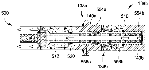
[0103] Figures 5A through 5N present stages of a gravel packing
procedure, in
one embodiment, using a packer assembly having alternative flowpath channels
through the packer elements of the packer assembly and through connected sand
control devices. Either of packer assembly 300 or packer assembly 400 may be
used. Figures 5A through 5N provide illustrative embodiments of the
installation
process for the packer assemblies, the sand control devices, and the gravel
pack in
accordance with certain aspects of the present inventions. These embodiments
involve an installation process that runs sand control devices and a packer
assembly
300 or 400, in a conditioned drilling mud. The conditioned drilling mud may be
a
non-aqueous fluid (NAF) such as a solids-laden oil-based fluid, along with a
solids-
laden water-based fluid. This process, which is a two-fluid process, may
include
techniques similar to the process discussed in International Patent
Application No.
WO 2004/079145. However, it should be noted that this example is simply for
illustrative purposes, as other suitable processes and equipment may also be
utilized.
[0104] In Figure 5A, sand control devices 550a and 550b and packer
assembly
134b are run into a wellbore 500. The sand control devices 550a and 550b are
comprised of base pipes 554a and 554b and sand screens 556a and 556b. The
sand control devices 550a and 550b also include alternate flow paths such as
internal shunt tubes 352 from Figure 3C. The illustrative shunt tubes 352 are
preferably disposed between the base pipes 554a, 554b and the sand screens
556a,
556b in the annular region shown at 552.
[0105] In the arrangement of Figure 5A, the packer 134b is installed
between
production intervals 108a and 108b. The packer 134b may be in accordance with
packer 210' of Figure 2. In addition, a crossover tool 502 with an elongated
washpipe 503 is lowered in the wellbore 500 on a drill pipe 506. The washpipe
503
- 20 -
CA 02779964 2012-05-03
WO 2011/062669 PCT/US2010/046329
is an elongated tubular member that extends into the sand screens 556a and
556b.
The washpipe 503 aids in the circulation of the gravel slurry during a gravel
packing
operation, and is subsequently removed.
[0106]
A separate packer 134a is connected to the crossover tool 502. The
crossover tool 502 and the packer 134a are temporarily positioned within a
string of
production casing 126. Together, the crossover tool 502, the packer 134a and
the
elongated washpipe 503 are run to the bottom of the wellbore 500. The packer
134a
is then set as shown in Figure 5B.
[0107]
Returning to Figure 5A, the conditioned NAF (or other drilling mud) 504 is
placed in the wellbore 500. Preferably, the drilling mud 504 is deposited into
the
wellbore 500 and delivered to the open-hole portion before the drill string
506 and
attached sand screens 550a, 550b and washpipe 503 are run into the wellbore
500.
The drilling mud 504 may be conditioned over mesh shakers (not shown) before
being placed within the wellbore 500 to reduce any potential plugging of the
sand
control devices 550a and 550b.
[0108]
In Figure 5B, the packer 134a is set in the production casing string 126.
This means that the packer 134a is actuated to extend an elastomeric element
against the surrounding casing string 126. The packer 134a is set above the
intervals 108a and 108b, which are to be gravel packed. The packer 134a seals
the
intervals 108a and 108b from the portions of the wellbore 500 above the packer
134a.
[0109]
After the packer 134a is set, as shown in Figure 5C, the crossover tool
502 is shifted into a reverse position. A carrier fluid 512 is pumped down the
drill
pipe 506 and placed into an annulus between the drill pipe 506 and the
surrounding
production casing 126 above the packer 134a. The carrier fluid 512 displaces
the
conditioned drilling fluid 504 above the packer 134a, which again may be an
oil-
based fluid such as the conditioned NAF. The carrier fluid 512 displaces the
drilling
fluid 504 in the direction indicated by arrows 514.
[0110]
Next, in Figure 50, the crossover tool 502 is shifted back into a circulating
position.
This is the position used for circulating gravel pack slurry, and is
sometimes referred to as the gravel pack position. The carrier fluid 512 is
then
pumped down the annulus between the drill pipe 506 and the production casing
126.
This pushes the conditioned NAF 504 through the base pipe 554a and 554b, out
the
sand screens 556a and 556b, sweeping the open-hole annulus between the sand
- 21 -
CA 02779964 2012-05-03
WO 2011/062669 PCT/US2010/046329
screens 556a and 556b and the surrounding wall 510 of the open hole portion of
the
wellbore 500, and through the crossover tool 502 back into the drill pipe 506.
The
flow path of the carrier fluid 512 is indicated by the arrows 516.
[0111] In Figures 5E through 5G, the production intervals 108a, 108b are
prepared for gravel packing. In Figure 5E, once the open-hole annulus between
the
sand screens 556a, 556b and the surrounding wall 510 has been swept with
carrier
fluid 512, the crossover tool 502 is shifted back to the reverse position.
Conditioned
drilling fluid 504 is pumped down the annulus between the drill pipe 506 and
the
production casing 126 to force the carrier fluid 512 out of the drill pipe
506, as shown
by the arrows 518. These fluids may be removed from the drill pipe 506.
[0112] Next, the packer 134b is set, as shown in Figure 5F. The packer
134b,
which may be one of the packers 300 or 400, for example, may be utilized to
isolate
the annulus formed between the sand screens 556a and 556b and the surrounding
wall 510 of the wellbore 500. While still in the reverse position, as shown in
Figure
5G, the carrier fluid 512 with gravel 520 may be placed within the drill pipe
506 and
utilized to force the drilling fluid 504 up the annulus formed between the
drill pipe 506
and production casing 126 above the packer 134a, as shown by the arrows 522.
[0113] In Figures 5H through 5J, the crossover tool 502 may be shifted
into the
circulating position to gravel pack the first subsurface interval 108a. In
Figure 5H,
the carrier fluid 512 with gravel 520 begins to create a gravel pack within
the
production interval 108a above the packer 134b in the annulus between the sand
screen 556a and the wall 510 of the open-hole wellbore 500. The fluid flows
outside
the sand screen 556a and returns through the washpipe 503 as indicated by the
arrows 524. In Figure 51, a first gravel pack 140a begins to form above the
packer
134b, around the sand screen 556a, and toward the packer 134a. In Figure 8J,
the
gravel packing process continues to form the gravel pack 140a toward the
packer
134a until the sand screen 556a is covered by the gravel pack 140a.
[0114] Once the gravel pack 140a is formed in the first interval 108a
and the sand
screens above the packer 134b are covered with gravel, the carrier fluid 512
with
gravel 520 is forced through the shunt tubes 352 and the packer 134b. The
carrier
fluid 512 with gravel 520 begins to create a second gravel pack 140b in
Figures 5K
through 5N. In Figure 5K, the carrier fluid 512 with gravel 520 begins to
create the
second gravel pack 140b within the production interval 108b below the packer
134b
in the annulus between the sand screen 556b and the walls 510 of the wellbore
500.
- 22 -
CA 02779964 2012-05-03
WO 2011/062669 PCT/US2010/046329
The fluid flows through the shunt tubes and packer 134b, outside the sand
screen
556b and returns through the washpipe 503 as indicated by the arrows 526.
[0115] In Figure 5L, the second gravel pack 140b begins to form below
the
packer 134b and around the sand screen 556b. In Figure 5M, the gravel packing
continues to grow the gravel pack 140b up toward the packer 134b until the
sand
screen 556b is covered by the gravel pack 140b. In Figure 5N, the gravel packs
140a and 140b are formed and the surface treating pressure increases to
indicate
that the annular space between the sand screens 556a and 556b and the walls
510
of the wellbore are gravel packed.
[0116] Figure 50 shows the drill string 506 and the washpipe 503 from
Figures
5A through 5N having been removed from the wellbore 500. The casing 126, the
base pipes 554a, 554b, and the sand screens 556a, 556b remain in the wellbore
500 along the upper 108a and lower 108b production intervals. Packer 134b and
the gravel packs 140a, 140b remain set in the open hole wellbore 500 following
completion of the gravel packing procedure from Figures 5A through 5N. The
wellbore 500 is now ready for production operations.
[0117] Figure 6A is a cut-away view of a wellbore 100. The wellbore 100
is
intended to be the same wellbore as wellbore 100 of Figure 2. In Figure 6A,
the
wellbore 100 is shown intersecting through a subsurface interval 114. Interval
114
represents an intermediate interval. This means that there is also an upper
interval
112 and a lower interval 116 (not shown in Figure 6A).
[0118] The subsurface interval 114 may be a portion of a subsurface
formation
that once produced hydrocarbons in commercially viable quantities but has now
suffered significant water or hydrocarbon gas encroachment. Alternatively, the
subsurface interval 114 may be a formation that was originally a water zone or
aquitard or is otherwise substantially saturated with aqueous fluid. In either
instance,
the operator has decided to seal off the influx of formation fluids from
interval 114
into the wellbore 100.
[0119] In the wellbore 100, a base pipe 205 is seen extending through
the
intermediate interval 114. The base pipe 205 is part of the sand control
device 200.
The sand control device 200 also includes a mesh, a wire screen, or other
radial filter
medium 207. The base pipe 205 and surrounding filter medium 207 is preferably
a
series of joints that are ideally about 5 to 35 feet in length.
- 23 -
CA 02779964 2012-05-03
WO 2011/062669 PCT/US2010/046329
[0120] The wellbore 100 has an upper packer assembly 210' and a lower
packer
assembly 210". The upper packer assembly 210' is disposed near the interface
of
the upper interval 112 and the intermediate interval 114, while the lower
packer
assembly 210" is disposed near the interface of the intermediate interval 114
and
the lower interval 116. The wellbore 200 is completed as an open hole
completion.
A gravel pack has been placed in the wellbore 200 to help guard against the
inflow of
granular particles into the wellbore 200. Gravel packing is indicated as
spackles in
the annulus 202 between the sand screen 207 and the surrounding wall 201 of
the
wellbore 200.
[0121] As noted, the operator desires to continue producing formation
fluids from
upper 112 and lower 116 intervals while sealing off intermediate interval 114.
The
upper 112 and lower 116 intervals are formed from sand or other rock matrix
that is
permeable to fluid flow. To accomplish this, a straddle packer 600 has been
placed
within the sand control device 200. The straddle packer 600 is placed
substantially
across the intermediate interval 114 to prevent the inflow of formation fluids
from the
intermediate interval 114.
[0122] The straddle packer 600 comprises a mandrel 610. The mandrel 610
is an
elongated tubular body having an upper end adjacent the upper packer assembly
210', and a lower end adjacent the lower packer assembly 210". The straddle
packer 600 also comprises a pair of annular packers. These represent an upper
packer 612 adjacent the upper packer assembly 210', and a lower packer 614
adjacent the lower packer assembly 210". The novel combination of the upper
packer assembly 210' with the upper packer 612, and the lower packer assembly
210" with the lower packer 614 allows the operator to successfully isolate a
subsurface interval such as intermediate interval 114 in an open hole
completion.
[0123] Another technique for isolating an interval along an open hole
formation is
shown in Figure 6B. Figure 6B is a side view of the wellbore 100 of Figure 2.
A
bottom portion of the intermediate interval 114 of the open-hole completion is
shown.
In addition, the lower interval 116 of the open-hole completion is shown. The
lower
interval 116 extends essentially to the bottom 136 of the wellbore 100 and is
the
lowermost zone of interest.
[0124] In this instance, the subsurface interval 116 may be a portion of
a
subsurface formation that once produced hydrocarbons in commercially viable
quantities but has now suffered significant water or hydrocarbon gas
encroachment.
- 24 -
CA 02779964 2012-05-03
WO 2011/062669 PCT/US2010/046329
Alternatively, the subsurface interval 116 may be a formation that was
originally a
water zone or aquitard or is otherwise substantially saturated with aqueous
fluid. In
either instance, the operator has decided to seal off the influx of formation
fluids from
the lower interval 116 into the wellbore 100.
[0125] To accomplish this, a plug 620 has been placed within the wellbore
100.
Specifically, the plug 620 has been set in the mandrel 215 supporting the
lower
packer assembly 210". Of the two packer assemblies 210', 210", only the lower
packer assembly 210" is seen. By positioning the plug 620 in the lower packer
assembly 210", the plug 620 is able to prevent the flow of formation fluids
into the
wellbore 200 from the lower interval 116.
[0126] It is noted that in connection with the arrangement of Figure 6B,
the
intermediate interval 114 may comprise a shale or other rock matrix that is
substantially impermeable to fluid flow. In this situation, the plug 620 need
not be
placed adjacent the lower packer assembly 210"; instead, the plug 620 may be
placed anywhere above the lower interval 116 and along the intermediate
interval
114. Further, the lower packer assembly 210" itself need not be positioned at
the
top of the lower interval 116; instead, the lower packer assembly 210" may
also be
placed anywhere along the intermediate interval 114. The functionality of the
packer
assemblies 210 described herein permit their use in a variety of manners
depending
on the properties and configuration of the formation and the wellbore. The
movement of the lower packer assembly 210" to any position along the
intermediate
interval 114 is one example. In other implementations, the upper packer
assembly
210' may be moved away from an interval interface to be in the middle of a
formation, depending on the manner in which the well is to be operated and the
circumstances presented by the formation.
[0127] A method 700 for completing an open-hole wellbore is also
provided
herein. The method 700 is presented in Figure 7. Figure 7 provides a flowchart
presenting steps for a method 700 of completing an open-hole wellbore, in
various
embodiments.
[0128] The method 700 includes providing a zonal isolation apparatus. This
is
shown at Box 710 of Figure 7. The zonal isolation apparatus is preferably in
accordance with the components described above in connection with Figure 2. In
this respect, the zonal isolation apparatus may include a base pipe, a screen
(or
other filter medium), at least one packer assembly having at least two
mechanically
- 25 -
CA 02779964 2012-05-03
WO 2011/062669 PCT/US2010/046329
set packer elements and an intermediate elongated swellable packer element,
and
alternative flow channels. The sand control devices may be referred to as sand
screens.
[0129] The method 700 also includes running the zonal isolation
apparatus into
the wellbore. The step of running the zonal isolation apparatus into the
wellbore is
shown at Box 720. The zonal isolation apparatus is run into a lower portion of
the
wellbore, which is preferably completed as an open-hole.
[0130] The method 700 also includes positioning the zonal isolation
apparatus in
the wellbore. This is shown in Figure 7 at Box 730. The step of positioning
the
zonal isolation apparatus is preferably done by hanging the zonal isolation
apparatus
from a lower portion of a string of production casing. The apparatus is
positioned
such that the base pipe and sand screen are adjacent one or more selected
intervals
along the open-hole portion of the wellbore. Further, a first of the at least
one packer
assembly is positioned above or proximate the top of a selected subsurface
interval.
[0131] In one embodiment, the open-hole wellbore traverses through three
separate intervals. These include an upper interval from which hydrocarbons
are
produced, and a lower interval from which hydrocarbons are no longer being
produced in economically viable volumes. Such intervals may be formed of sand
or
other permeable rock matrix. The intervals also include an intermediate
interval from
which hydrocarbons are not produced. The formation in the intermediate
interval
may be formed of shale or other substantially impermeable material. The
operator
may choose to position the first of the at least one packer assembly near the
top of
the lower interval or anywhere along the non-permeable intermediate interval.
[0132] The method 700 next includes setting the mechanically set packer
elements in each of the at least one packer assembly. This is provided in Box
740.
Mechanically setting the upper and lower packer elements means that an
elastomeric (or other) sealing member engages the surrounding wellbore wall.
The
packer elements isolate an annular region formed between the sand screens and
the
surrounding subsurface formation above and below the packer assemblies.
[0133] The method 700 also includes injecting a particulate slurry into the
annular
region. This is demonstrated in Box 750. The particulate slurry is made up of
a
carrier fluid and sand (and/or other) particles. One or more alternate flow
channels
allow the particulate slurry to bypass the mechanically set packer elements
and the
intermediate swellable packer element. In this way, the open-hole portion of
the
- 26 -
CA 02779964 2012-05-03
WO 2011/062669 PCT/US2010/046329
wellbore is gravel-packed above and below (but not between) the mechanically
set
packer elements.
[0134] The method 700 further includes producing production fluids from
intervals
along the open-hole portion of the wellbore. This is provided at Box 760.
Production
takes place for a period of time. Over the period of time, the upper packer
element,
the lower packer element, or both, may fail. This permits the inflow of fluids
into an
intermediate portion of the packer along the swellable packer element. This
will
cause the swellable packer element to swell, thereby once again sealing the
selected interval. This is shown at Box 770 of Figure 7.
[0135] It is acknowledged that it would be preferable for the swellable
packer
element to be exposed to fluids prior to gravel packing. In this way the
swellable
packer element could swell and establish a good annular seal with the
surrounding
wall of the open-hole portion of the wellbore before a packer element failure.
However, such a technique presents two problems: (1) alternate flowpath
channels
are required through the packer assemblies, e.g., assemblies 210' and 210", to
pack
the lower interval(s), and (2) the time value of the drilling rig precludes
waiting days
or weeks for the swelling element to effectively seal. Therefore, such a
procedure is
not preferred.
[0136] In many cases, fluids native to a subsurface interval adjacent
the swellable
packer element may already exist. These fluids will cause the swellable packer
element to swell and to engage the surrounding wellbore wall without failure
of either
of the mechanically set packer elements. Thus, the step 770 of allowing the
swellable packer element to swell may occur naturally. This step 770 may also
take
place by the operator affirmatively injecting an actuating chemical into the
base pipe.
[0137] In one embodiment of the method 700, flow from a selected interval
may
be sealed from flowing into the wellbore. For example, a plug may be installed
in the
base pipe of the sand screen above or near the top of a selected subsurface
interval.
This is shown at Box 780. Such a plug may be used below the lowest packer
assembly, such as the second packer assembly from step 735.
[0138] In another example, a straddle packer is placed along the base pipe
along
a selected subsurface interval to be sealed. This is shown at Box 785. Such a
straddle may involve placement of sealing elements adjacent upper and lower
packer assemblies (such as packer assemblies 210', 210" of Figure 2 or Figure
6A)
along a mandrel.
- 27 -
CA 02779964 2012-05-03
[0139] While it will be apparent that the inventions herein described are
well
calculated to achieve the benefits and advantages set forth above, it will be
appreciated that the inventions are susceptible to modification, variation and
change.
Improved methods for completing an open-hole wellbore are provided so as to
seal off
one or more selected subsurface intervals. An improved zonal isolation
apparatus is
also provided. The inventions permit an operator to produce fluids from or to
inject
fluids into a selected subsurface interval.
- 28 -