Note: Descriptions are shown in the official language in which they were submitted.
CA 02780115 2012-05-04
W02011/054465 1
PCT/EP2010/006546
Large load carrier
The invention relates to a large load carrier made of plastic,
having a bottom that accommodates the loads, on the underside of
which standing feet are disposed at least in the corner regions,
and which is surrounded by a double-wall frame, whereby the inner
and outer wall of the frame are connected with one another by way
of vertical crosspieces, and strip-shaped protective profiles are
disposed in the lower frame region, between two standing feet, in
each instance, whereby the back side of the protective profile is
supported on the inner wall of the frame.
Such large load carriers are known, for example, from the German
patent 10 2004 049 201. The problems that underlie the previously
known large load carriers, and also the one. according to the
invention, can be seen in that such containers are stacked, with
several of them one on top of the other, whereby the lowest
container has to carry up to 3 metric tons.
For this reason, such a stack is not lifted and set down by the
forklift truck driver. Instead, he moves the forks of the
forklift against the lower edge of the bottommost container or the
CA 02780115 2012-05-04
W02011/054465
PCT/EP2010/006546
2
bottommost pallet in the stack, and displaces the stack in this
manner, to the desired location, over a hall floor that is
generally rough.
In this connection, of course, damage or destruction of the
plastic container or of the pallet frequently occurs in this
region.
In the case of the previously known container, this problem is
supposed to be counteracted using a metal profile strip, which is
disposed in the lower frame region of the container, between two
standing feet. This previously known profile strip had a U-shaped
cross-section open toward the front, into which the forks of the
forklift are supposed to engage.
In this connection, it can, of course, happen that the forks of
the forklift do not hit the U profile, but rather penetrate into
the container bottom above the profile strip and cause damage
here.
The invention is therefore based on the task of providing a
protective profile that is as inexpensive as possible, which
CA 02780115 2014-10-23
28005-22
3
prevents penetration of the forks of the forklift into the
container bottom.
Some embodiments of the invention may accomplish this task in
that the protective profile is a plastic part, on the
longitudinal edge of which an insertion strip for insertion
into the interstice between inner and outer wall of the frame
is formed on and forms a unit with the profile.=
In this way, the region between the actual protective profile and
the container bottom that lies behind it is bridged by means of
the insertion strip, so that penetration of the'forklift forks
=
into this region is precluded. =
Furthermore, the unit composed of insertion strip and protective
profile is produced using the injection-molding method, and is
therefore inexpensive, in any case more inexpensive than the
previously known metal profile strip.
In some embodiments, it is provided that the insertion strip has
recess slots for accommodating the crosspieces that connect the
-inner and outer wall with one another.
CA 02780115 2012-05-04
W02011/054465
PCT/EP2010/006546
4
In this way, a secure hold within the double-wall frame is
guaranteed.
Attachment of the protective profiles can take place, for example,
by means of recesses in the feet, into which the ends of the
profile are introduced, and afterward the foot is installed onto
the container bottom.
It is also possible that the profile is put together from multiple
individual elements that are screwed on or clipped on or also
welded on between the ribs, within the frame.
The protective profile also does not have to consist of individual
strips that reach from foot to foot, but rather can be configured
as a circumferential frame element that is laid into the
aforementioned recesses in the frame, and afterward the feet are
installed onto the container bottom.
In the following and using the drawings, however, only the holding
method known from the state of the art for attachment of the
protective profiles is explained, by means of tongues formed onto
the feet, whereby the tongues engage into corresponding recesses
at the profile ends.
CA 02780115 2014-10-23
28005-22
In some embodiments, it is provided that the protective profile
has a cross-section that is U-shaped toward the outside, similar
to the previously known metal profile.
=
In a further exemplary embodiment, it is provided,
that the protective profile has the shape of an L
standing on its head in cross-section, whereby the vertical L
Shank is guided in an arc all the way to the inner wall of the
frame, at its end.
This is therefore a profile that is open toward the bottom, in
which the forks of the forklift are prevented from slipping upward
by the upper L shank.
As additional protection, it is provided,
that a metal profile that is also L-shaped can be laid into the
region having the L-shaped cross-section, which profile can also
be held by the tongues formed onto the foot, in each instance.
However, the attachment alternatives mentioned above can also be
used here. Laying in the metal profile is optional and is
generally only required if the load to be displaced is
particularly great.
CA 02780115 2014-10-23
28005-22
6
=
In another exemplary embodiment, it is
proposed that the protective profile has a region that proceeds
vertically from the insertion strip, in cross-section, from which
region a slanted region runs in the direction of the inner wall of
the frame, at an obtuse angle, the end of which region has a
horizontal region that is supported in the inner wall of the
frame, whereby crosspieces proceed horizontally both from the
vertical region and from the region that runs at a slant, which
crosspieces have a distance from the inner wall of the frame in
the unstressed state.
The region of the protective profile that proceeds vertically
serves as an engagement surface for the forks of the forklift for
displacement of the container, while the slanted region of the
protective profile offers the forks a different type of engagement
surface, because of its resilient properties, which are, however,
limited by the horizontal crosspieces that serve as a stop, in
such a manner that the container is lifted slightly and tilted,
thereby facilitating its displacement.
A further modification of this solution is provided, which
differs from the preceding exemplary embodiment
CA 02780115 2014-10-23
28005-22
7
solely in that the vertical region of the protective profile is
left out.
To protect the lower edge of the outer wall of the frame and as a
stop for the forks of the forklift, it is provided,
that a projection that projects outward is provided on
the profile, at the transition to the insertion strip part, which
projection lies against the underside of the outer wall of the
frame.
In all the exemplary embodiments that have been presented up to
now, it is provided, that the insertion
strip is configured in L shape in cross-section,.whereby the
vertical L shank lies against the inside of the outer wall of the
frame, while the horizontal L shank connects the insides of outer
wall and inner wall with one another, whereby vertical
intermediate walls are provided over the entire length of the
= insertion strip, at a distance from one another.
In this way, the insertion strip is also a component that has a
light construction but is nevertheless stable, and forms a unit
with the protective profile.
CA 02780115 2014-10-23
28005-22
8
In connection with the protective profiles presented up to now,
it has been assumed that the rear wall of the frame reaches
down lower than the front wall, so that the actual protective
profile is visible.
Alternatively, both walls can also have the same height, so
that the protective profile disappears completely in the wall.
The recesses in the feet, which are installed onto the
container bottom after the profile is laid in, then serve to
fix the profile in place.
According to another aspect of the present invention, there is
provided large load carrier made of plastic, having a bottom
that accommodates the loads, on the underside of which standing
feet are disposed at least in corner regions, and which is
surrounded by a double-wall frame, wherein an inner and an
outer wall of the frame are connected with one another by way
of vertical crosspieces, and strip-shaped protective profiles
are disposed in a lower frame region, between two standing
feet, in each instance, wherein a back side of a protective
profile is supported on the inner wall of the frame, wherein
the protective profile is a plastic part, on a longitudinal
edge of which an insertion strip for insertion into an
interstice between inner and outer walls of the frame is formed
on and forms a unit with the profile.
In the following, exemplary embodiments of the invention will ,
be presented and explained in greater detail using drawings.
CA 02780115 2014-10-23
28005-22
These show: 8a
Fig. 1 the foot region of a large load carrier in a
truncated representation, with a protective strip
according to a first alternative
Fig. 2 sectional view along the line A-A in Fig. 1
CA 02780115 2012-05-04
W02011/054465
PCT/EP2010/006546
9
Fig. 3 view of the protective profile according to Fig. 2
from the front and from the rear
Fig. 4 view according to Fig. 1 with a protective profile
according to a second alternative
Fig. 5 sectional view along the line A-A in Fig. 4
Fig. 6 protective profile according to the second
alternative in a view from the front and from the
rear
Fig. 7 view according to Fig. 1 with a protective profile
according to a third alternative
Fig. 8 sectional view along the line A-A from Fig. 7
Fig. 9 protective profile according to the third
alternative in a view from the front and from the
rear
Fig. 10 view according to Fig. 1 with a protective profile
according to a fourth alternative
CA 02780115 2012-05-04
W02011/054465
PCT/EP2010/006546
Fig. 11 sectional view along the line A-A from Fig. 10
Fig. 12 protective profile according to the fourth
alternative in a view from the front and from the
rear
Fig. 13 view of the detail from Fig. 1 from below, without
the protective profile being inserted
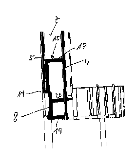
In Figures 1, 4, 7, and 10, a corner region of a large load
carrier is shown, which is indicated in general with the reference
symbol 1. The large load carrier 1 consists of a bottom 2, which
is surrounded by a double-wall frame 3.
The structure of this
frame is more precisely evident from Figure 13.
From this drawing, it is also evident that the rear wall 4 of the
frame 3 reaches further down than the front wall 5 of the frame.
The vertical crosspieces 6 that are vertically disposed and
connect the front and rear wall with one another can also be seen.
CA 02780115 2015-04
= 28800-27
,
11
A protective profile 8 is laid into the recess 7 formed by the
different lengths of front and rear wall, which profile has
recesses 10 at its ends 9, into which tongues 11 engage, which
tongues are formed onto a foot 13 installed onto the bottom in the
lateral corner region.
The protective profile 8 of the four different embodiments of this
invention all have in common that an insertion strip 15 is
injection-molded onto the upper edge 14 of the actual protective
profile 8, which strip is inserted into the interstice 7 between
the inner wall 4 and the outer wall 5 of the frame 3.
As is evident from Figure 3, vertical recesses 16 are formed in on
the protective profile side of the insertion strip 15, which
recesses correspond to the crosspieces 6 in the interstice 7 of
the frame 3.
As the figure of the back side of the profile 8, 15 shows, the
insertion strip 15 has a front wall that is continuous with the
exception of the recesses 16, which wall lies against the inside
of the front wall 5 of the frame 3, and has a shank 17 that
proceeds horizontally from this front wall and connects the front
wall 5 and the rear wall 4 with one another in the inserted state.
CA 02780115 2012-05-04
W02011/054465
PCT/EP2010/006546
12
To increase the stability, the insertion strip 15 and the
protective profile 8 are reinforced with perpendicular
intermediate walls 18.
In the figures, parts that are the same are provided with the same
reference symbols, in each instance. In the following, the
protective profiles 8 that have different configurations will now
be described. The protective profile 8 shown in Figures 2 and 3
has a cross-section that is approximately U-shaped and open to the
outside, whereby the lower U shank makes a transition into a
crosspiece 19 that is disposed horizontally and points in the
direction of the rear wall 4. Above the crosspiece 19, another
horizontal crosspiece 20 is provided, which also supports itself
on the rear wall 4, like the crosspiece 19.
In Figures 5 and 6, a second alternative of the protective profile
8 is shown. It has a shoulder 21 directed in the direction of the
inner wall 4, horizontally from the insertion part 15, but this
shoulder ends at a distance from this inner wall 4 and makes a
transition there into a vertical region 22, which reaches all the
way to the inner wall 4 at its end, in the shape of an arc. In
the case of this exemplary embodiment, as well, another horizontal
CA 02780115 2012-05-04
W02011/054465
PCT/EP2010/006546
13
crosspiece 23 is provided for supporting the profile 8 on the
inner wall 4.
For further reinforcement, a metal profile strip 30 that is also
L-shaped and is held by means of the tongues 11 can also be laid
into the profile 8.
In Figures 8 and 9, a third alternative of a protective profile 8
is shown, in which a vertical region 24 runs downward, at first,
from the insertion strip part 15, and them makes a transition into
a slanted region 25, in an obtuse angle, whereby the slant runs in
the direction of the inner wall 4. A crosspiece strip that
reaches horizontally all the way to the inner wall 4 is formed
onto the end of this slanted region 15.
Two crosspieces 26 are provided both in the vertical region and in
the slanted region, but they end at a distance in front of the
inner wall 4. Because of the elastic properties of the profile
material (plastic), the profile 8 absorbs part of the energy when
the forklift forks attack it, until the crosspieces 26 lie against
the inner wall 4.
CA 02780115 2012-05-04
= 28800-27
14
Finally, in Figures 11 and 12, a fourth alternative is shown,
which differs from the third alternative only in that the vertical
region 24 was left out. The two exemplary embodiments have in
common a projection 27 that projects outward, is situated at the
transition of the profile 8 to the insertion strip part 15, and
lies against the lower edge of the outer wall 5 of the frame 3.