Note: Descriptions are shown in the official language in which they were submitted.
CA 02780192 2012-05-07
WO 2011/057790
PCT/EP2010/006891
Method and device for controlling an artificial
orthotic or prosthetic joint
The invention relates to a method and a device for
controlling an orthotic or prosthetic joint of a lower
extremity with a resistance device, which is assigned
at least one actuator by way of which the bending
and/or stretching resistance is changed in dependence
on sensor data, information pertaining to the state
being provided by way of sensors during the use of the
joint.
Appropriate prosthetic care for geriatric patients
requires that the needs of the patients, respective
activities and medical necessities are addressed. The
need for safety is often at the forefront, so that
while standing a locking of the knee joint is desired.
It is intended that the locking can as far as possible
be activated both load-dependently and angle-
dependently and induce the feeling of stability in
every standing situation, since the coordinating
capability, mobility and physical strength of such
patients may sometimes be limited.
If the patient is mobile, during walking there should
be a high flexion resistance in the standing phase in
order to avoid unwanted bending, since bending often
cannot be compensated quickly enough by a stretching
from the hip.
Sitting on the other hand requires a low resistance,
both in the direction of extension and in the direction
of flexion, in order that the patient can move
unhindered.
It may also be necessary to provide a triggering of the
swing phase, in order to make walking more comfortable
for the patient.
CA 02780192 2012-05-07
WO 2011/057790
PCT/EP2010/006891
- 2 -
Artificial joints, in particular knee joints, for
ortheses or prostheses have an upper connection part
and a lower connection part, which are connected to
each other by way of a joint device. In the case of a
knee joint, receptacles for an upper leg stump or an
upper leg rail are arranged on the upper connection
part, while a lower leg shaft or a lower leg rail is
arranged on the lower connection part. In the simplest
case, the upper connection part and the lower
connection part are connected to each other pivotably
by a single-axis joint. Only in exceptional cases is
such an arrangement sufficient for ensuring the desired
success, for example support in the case of the use of
an orthesis or a natural gait pattern in the case of
use in a prosthesis.
In order to represent as naturally as possible or be
conducive to the various requirements during the
various phases of a step, or in the case of other
tasks, resistance devices which offer a flexion
resistance or an extension resistance are provided. The
flexion resistance is used to set how easily the lower
connection part can be pivoted with respect to the
upper connection part in the direction of flexion. In
the case of a knee joint, the flexion resistance is
therefore used to set how easily the lower leg shaft or
the lower leg rail swings backward in relation to the
upper leg shaft or the upper leg rail when a force is
applied. The extension resistance retards the forward
movement of the lower leg shaft or the lower leg rail
and may form a stretching stop. In the case of other
types of joint, such as the hip joint or the ankle
joint, these statements apply in a way corresponding to
the kinematic conditions.
CA 02780192 2012-05-07
WO 2011/057790
PCT/EP2010/006891
- 3 -
It is possible by using settable resistance devices to
adapt the respective flexion resistance and extension
resistance to the user of the prosthetic or orthotic
device or to make allowance for different gait or
movement situations, in order to be able to offer an
adapted resistance under changing conditions.
DE 10 2008 008 284 Al discloses an orthopedic knee
joint with an upper part and a lower part arranged
pivotably thereon and assigned a number of sensors, for
example a bending angle sensor, an acceleration sensor,
an inclination sensor and/or a force sensor. The
extension stop is set in dependence on the sensor data
determined.
DE 10 2006 021 802 Al describes a control of a passive
prosthetic knee joint with adjustable damping in the
direction of flexion for the adaptation of a prosthetic
device with upper connecting means and a connecting
element to an artificial foot. The adaptation is for
climbing stairs, a low-torque lift of the prosthetic
foot being detected and the flexion damping being
lowered in a lifting phase to below a level that is
suitable for walking on level ground. The flexion
damping may be raised in dependence on the changing of
the knee angle and in dependence on the axial force
acting on the lower leg.
DE 10 2007 053 389 Al describes a method and a device
for controlling an orthopedic joint of a lower
extremity with at least one degree of freedom, with an
adjustable actuator for adapting to walking situations
that differ from walking on level ground an orthopedic
device which has upper connecting means to a limb and
an orthopedic joint arranged in a jointed manner
distally in relation to the connecting means. In this
case, a number of parameters of the orthopedic device
CA 02780192 2012-05-07
WO 2011/057790
PCT/EP2010/006891
- 4 -
are detected by way of sensors, the detected parameters
are compared with criteria that have been produced on
the basis of a number of parameters and/or parameter
profiles and stored in a computer unit, and a criterion
that is suitable on the basis of the parameters or
parameter profiles determined is selected. On the basis
of the criterion selected, bending resistances, bending
extents, driving forces and/or how they vary over time
are set in order to control special functions that
deviate from walking on level ground. A tilting angle
of part of the orthopedic device in space and/or a
variation of a change in tilting angle of part of the
orthopedic device may be used as parameters.
Furthermore, the prior art discloses what are known as
brake knee joints, in which the flexion resistance and
extension resistance are mechanically increased as
axial loading becomes greater. This is achieved in the
simplest case by providing two braking surfaces which
are pressed onto each other by the ground reaction
force. Such a configuration cannot be used on the
braking device for modern prosthetic knee joints with
controlled resistance devices.
It has proven successful for knee joints to offer a
high resistance in the standing phase during walking or
while standing, the joint not being locked completely.
In the case of a fully stretched knee joint, the
bending of the joint is prevented by the force vector
lying ahead of the joint axis, and consequently the
joint being pressed into the stretching stop. As soon
as the force vector migrates behind the joint axis,
there is the risk of the joint buckling. It is
therefore necessary likewise to offer an increased
resistance in a slightly bent position. The fact that
the joint does not completely lock in a slightly bent
position has the advantage that the user of the joint
CA 02780192 2012-05-07
WO 2011/057790
PCT/EP2010/006891
- 5 -
still has possibilities of intervening in the movement
of the joint. Should he for example be standing on
stairs and lose his balance, a locked joint would cause
him to fall in an uncontrolled manner, whereas he can
still bend a joint with a high flexion resistance by
means of the stump force and thereby mitigate the
consequences of falling or prevent falling entirely.
Likewise, high damping when standing makes it easier
for the joint to be maneuvered in confined spaces or to
be set down.
If the joint only offers a high resistance and does not
completely lock, it is not possible for example for
loading to be applied to the prosthesis when standing
on inclined surfaces if the ground reaction force
vector migrates too far toward the heel, and
consequently no longer lies ahead of the knee axis but
behind the knee axis and thereby bends the knee.
Standing on a bent knee is also not possible, because
the knee bending has the effect that the knee joint
axis migrates ahead of the ground reaction force vector
and, as a result, the knee is bent further.
Furthermore, the prior art discloses devices in which a
separate mode must be set in order to activate locked
standing on a ramp or on a bent knee. In such a mode,
the joint cannot be bent any further than up to a
settable angle. To walk any further or sit down, it is
necessary to change deliberately to another mode.
The object of the present invention is to provide a
method and a device with which it is possible
automatically to load the knee with an increased
resistance or to lock it in certain situations, without
a deliberate activation or deactivation of the mode
having to be performed.
CA 02780192 2016-06-15
-6-
SUMMARY
Certain exemplary embodiments can provide a method for
controlling an orthotic or prosthetic joint of a lower
extremity with a resistance device, which is assigned at
least one actuator by way of which at least one of a bending
and stretching resistance is changed in dependence on sensor
data, information pertaining to a state of the joint being
provided by way of sensors during use of the joint, wherein
during a standing phase or when standing, the resistance is
increased from an initial value up until a locking of the
joint in dependence on a measured ground reaction force, and
after the resistance is increased, reducing the resistance
in dependence on an inertial angle of a connection part of
the joint.
Other exemplary embodiments can provide a device for
carrying out the method as claimed in claim 1, comprising a
settable resistance device, which is arranged between two
components of an artificial orthotic or prosthetic joint
that are arranged one against the other in a jointed manner,
with a control device and sensors that detect information
pertaining to the state of the device, wherein a setting
device is provided and a loading-dependent change in
resistance can be activated or can be deactivated by way of
the setting device.
Other exemplary embodiments can provide a method for
controlling an orthotic or prosthetic joint of a lower
extremity, comprising: providing a resistance device, at
least one actuator, and a plurality of sensors; changing at
least one of a bending resistance and a stretching
CA 02780192 2016-06-15
-6a-
resistance in the joint based on sensor data provided by the
plurality of sensors; providing information from the
plurality of sensors related to a state of the joint during
use of the joint; increasing the at least one of the bending
resistance and the stretching resistance from an initial
value up to a locking of the joint in a standing phase or
when standing based on a measured ground reaction force;
wherein after increasing the at least one of the bending
resistance and the stretching resistance, reducing the at
least one of the bending resistance and the stretching
resistance based on an inertial angle of a connection part
of the joint.
CA 02780192 2016-06-15
-6b-
The method according to the invention for controlling
an orthotic or prosthetic joint of a lower extremity
with a resistance device, which is assigned at least
one actuator by way of which the bending and/or
stretching resistance is changed in dependence on
sensor data, information pertaining to the state being
provided by way of sensors during the use of the knee
joint, provides that, in the standing phase or when
standing, the resistance is increased from an initial
resistance up until a locking of the joint in
dependence on the measured ground reaction force. After
the detection of the standing phase or of standing, in
the presence of a predetermined ground reaction force
the joint resistance is increased up until locking of
the joint, in order to go automatically into a safe or
secured state. The resistance may be increased
continuously during the standing phase or when standing
when there is increasing loading, the increase
advantageously being carried out only whenever a
threshold value, for example of the ground reaction
force, is reached or exceeded. The ground reaction
force may in this case be measured directly. In most
cases, however, only a meaningful component of the
ground reaction force, such as for example the
component in the direction of the lower leg, is
measured. The initial resistance may be settable, so
that the level from which the resistance is increased,
and to which it is possibly reduced again, can be
adapted to the patient.
CA 02780192 2012-05-07
WO 2011/057790
PCT/EP2010/006891
- 7 -
In order to use the state of increased flexion
resistance only whenever there is a risk of buckling of
the knee joint, it is provided that the locking is only
performed whenever the ground reaction force vector
runs behind the knee axis, so that under further
loading in the axial direction of the fitted leg an
increasing bending would occur. Depending on the
structure of the prosthesis or orthesis, this may take
place at different bending angles. Particularly stably
constructed joints, in which the ground reaction force
vector lies well ahead of the joint axis in the
stretched state, are only subjected to an increased
resistance at a relatively great joint angle, while
less stably constructed joints require an increased
resistance already before that. A less stable and also
less safe structure, for example due to a forward
shifting of the knee joint, provides advantages for the
patient if the buckling of the knee joint is prevented
and the prosthesis is secured by the control. Under
otherwise the same conditions, the forward shifting of
the knee joint leads to quicker and greater knee
bending when the heel strikes and dampens the impact.
Furthermore, the hip-bending torque for initiating the
swing phase and for bending the prosthesis in the swing
phase decreases, which has a positive effect for the
patient. The forward shifting of the knee joint also
brings about a shortening of the length of the
prosthesis in the mid-swing phase, which reduces the
risk of the patient stumbling. Consequently, the
resistance is also increased in dependence on the joint
angle or the inertial angle of a joint component, in
particular of the lower leg part and the upper leg
part, since the ground reaction force vector can lie
behind the knee joint axis even with a stretched knee
joint and a stable structure when standing on a sloping
level, which may lead to a buckling of the knee joint.
The inertial angle is helpful especially to prevent
CA 02780192 2012-05-07
WO 2011/057790
PCT/EP2010/006891
- 8 -
locking during sitting, that is to say with an almost
horizontal upper leg.
The resistance may also be increased or locked in
dependence on the distance of the ground reaction force
from a reference point on a connection part on the
joint or in dependence on a torque about the reference
point.
In order after increasing the resistance up to a lock
to be able to use the joint device for activities other
than standing, it is provided that the resistance is
reduced, for example to the initial value, in
dependence on an inertial angle, a changing of the
inertial angle and/or the inertial angle velocity of a
connection part of the joint. It is therefore detected
that part of the joint is being moved, for example that
the load on the prosthesis is being relieved or the
user is rolling forward or backward by way of the
prosthesis. It is detected from this that standing no
longer applies, so that the resistance must be reduced.
Standing is the term used when the prosthetic foot is
set down and the wearer of the prosthesis is not in a
forward or backward movement. An axial load or ground
reaction force is exerted on the prosthesis and the
prosthetic foot. The prosthetic knee joint is usually
stretched, although standing with a bent knee is also
intended to be possible by the present method. This
loading-dependent behavior is preferably implemented as
a "function". A function can be given clearance or
locked. If it is given clearance, it is always
activated when the sensor criteria for increasing the
resistance are satisfied. If the criteria are no longer
satisfied, the joint can go over into other control
states, such as for example a swing phase control. If
it is locked, it can no longer be activated. The other
CA 02780192 2012-05-07
WO 2011/057790
PCT/EP2010/006891
- 9 -
control states are not affected by this however. It is,
however, also possible to implement the control as a
"mode".
The standing mode is a control behavior that has to be
activated separately. Unlike a standing function, which
exists permanently and enquires whether or not the
criteria for the standing function are satisfied, to
then perform a corresponding adaptation of the
resistance or resistances, the mode, in the present
method the standing mode, is activated by way of an
activity to be carried out deliberately. If the method
is implemented as a mode, the function of the joint is
confined exclusively to the behavior described. The
transition to other control states, such as for example
a swing phase control, is only possible after
deliberate deactivation of the mode.
It is likewise possible that, in spite of the presence
of the corresponding ground reaction force and the
joint angle, the increasing of the resistance is not
initiated at all if there is an inertial velocity of a
joint component, that is to say a standing state does
not apply. The locking of the joint can likewise be
ruled out in dependence on the inertial angle, for
example if the upper leg part is inclined forward in
the walking direction, that is to say the proximal end
of the upper leg part lies ahead of the distal end of
the upper leg part in the walking direction.
To determine the inertial angle of a connection part,
it is possible to determine it directly or from the
inertial angle of another connection part in
conjunction with a corresponding joint angle.
When the joint is relieved of loading, for example when
lifting the leg, a hysteresis may be provided, reducing
CA 02780192 2012-05-07
WO 2011/057790
PCT/EP2010/006891
- 10 -
the resistance again only when there is relatively low
loading, that is to say that the threshold value must
be fallen below significantly in order to bring about a
reduction in resistance.
In order to reduce the resistance again when continuing
to walk or sitting down, the inertial angle velocity of
the connection part, the knee angle, the knee angle
velocity, the changing of the distance of the ground
reaction force from a connection part and/or the
changing of the inertial angle of a connection part may
be used. For example, the knee angle, the knee angle
velocity and the inertial angle velocity are well
suited for detecting forward walking. It is also
provided that the locking of flexion is initiated
whenever the knee angle velocity is zero or virtually
zero, in order to ensure that the knee joint is only
locked while at a standstill. This state may occur if
the force vector lies behind the knee axis, but
temporarily, until the flexion lock responds, the
patient using the hip to compensate for the bending, so
that the knee torque and the knee angle velocity become
zero. When standing, the activated flexion lock may
have the effect that the knee torque is bending,
without the knee giving way.
The distance of the ground reaction force vector from a
connection part is well suited for detecting sitting
down. The reducing of the resistance may in this case
be performed discretely or continuously when a
threshold for the parameters mentioned is exceeded.
The reducing as well as the increasing of the
resistance may be initiated by a number of parameters,
for example loading, joint angle and inertial angle,
there being various form functions by way of which it
is determined by linking a number of conditions whether
CA 02780192 2012-05-07
WO 2011/057790
PCT/EP2010/006891
- 11 -
and by which factor the resistance is increased or
reduced. This produces gentle locking and unlocking of
the joint in dependence on a number of influencing
variables.
Since a locking of the joint when sitting is sometimes
undesired, for example to prevent a locked knee joint
and a jamming joint when driving a car, it is provided
that the resistance cannot be increased up to a lock if
the upper leg part is almost horizontal. For this
purpose, the inertial angle of the upper leg part is
determined. The increase of the resistance up to a
locking of the joint that is described above may be
part of an overall control of a joint; it is also
possible that it is the only function of a joint. It
may in this case form a mode to be deliberately
activated, which can be activated or deactivated by way
of a setting device. It is likewise possible that this
function is latently present, so that this function is
present at all times in the normal control program of a
knee joint during the standing phase or when standing
if the preconditions for locking the joint are
satisfied.
The device for carrying out the method, as it is
described above, provides a settable resistance device,
which is arranged between two components of an
artificial orthotic or prosthetic joint that are
arranged one against the other in a jointed manner and
has a control device and sensors that detect
information pertaining to the state of the device. Also
provided is a setting device, by way of which the
loading-dependent change in resistance can be activated
and/or can be deactivated.
CA 02780192 2012-05-07
WO 2011/057790
PCT/EP2010/006891
- 12 -
An exemplary embodiment of the device is explained in
more detail below on the basis of the accompanying
figures, in which:
Figure 1 shows a profile of the variation in
resistance;
Figure 2 shows criteria for controlling the change in
resistance;
Figure 3 shows a schematic
representation of a
prosthesis;
Figure 4 shows a schematic representation for the
calculation of a distance;
Figure 5 shows a schematic representation for the
calculation of a distance on the basis of a
number of sensor values; and
Figure 6 shows a convention of the angle indications.
In Figure 1, the variation in the resistance R or the
change in resistance is shown against the loading due
to the ground reaction force GRF. In the standing phase
or while standing, the normal standing phase resistance
Rstance is set to obtain a gait pattern that is as
natural as possible with a prosthesis or orthesis
during walking. If a threshold value of the ground
reaction force GRF is exceeded, the resistance R is
raised, a continuous increasing of the resistance R up
to a block resistance Rblock being achieved during the
standing phase with increasing loading due to the
ground reaction force GRF. This blocking resistance
Rblock effectively prevents a flexion of the knee joint,
but is advantageously dimensioned such that no
mechanical damage occurs if a loading limit for
CA 02780192 2012-05-07
WO 2011/057790
PCT/EP2010/006891
- 13 -
individual components of the prosthesis or orthesis is
exceeded. If in the further course of events the ground
reaction force GRF is then reduced again, it is
provided that the resistance is only reduced again from
the blocking value Rblock when the loading has gone below
the threshold value that was reached to initiate an
increase in resistance. After falling below this
threshold value, the resistance R is then reduced to
the normal standing phase level until the standing
phase resistance Rstance is reached.
There are various ways in which the resistance to be
set can be determined; in Figure 2, form functions that
can be used as factors for calculating the resistance R
are represented. The curve on the right shows the
function for the loading due to the ground reaction
force GRF, which has been normalized. The curve on the
left shows how further functions fN can be entered in
the calculation of the setpoint resistance. Indicators
for a movement of the joint, such as the knee angle
velocity, the inertial angle velocity, the deviation of
the distance of the ground reaction force of a joint
part from the point in time of the lock coming into
effect or the deviation of the inertial angle of a
joint part before the lock comes into effect may serve
as arguments for these functions. All of the functions
fl to fN may be linked by multiplication to arrive at
the setpoint value of the resistance, in that for
example they weight the difference of a standing phase
resistance from a blocking resistance and thus
determine by which amount the standing phase resistance
Rstance s increased. The maximum value for the blocking
resistance Rblock reduced by the value for the normal
standing phase resistance Rstance is multiplied by the
two arguments fl and fN. If a function is zero, the
standing phase resistance Rstance remains unchanged; as
soon as all of the functions fl to fN are greater than
CA 02780192 2012-05-07
WO 2011/057790
PCT/EP2010/006891
- 14 -
0, the standing phase resistance Rstance is increased or,
if the functions become smaller, the increased
resistance is reduced. The resistance R is therefore
calculated from
R.= Rstance (Rblock ¨ Rstance) *fl(ARGI)*f2(ARG2)*...-1-fN(ARGN)
After reducing the resistance following activation of
the block, a set of functions fN that is different from
that used for activating the lock may be used.
In Figure 3, a schematic representation of a leg
prosthesis with an upper leg shaft 1 for receiving an
upper leg stump is shown. The upper leg shaft 1 is also
referred to as the upper connection part. Arranged on
the upper connection part 1 is a lower connection part
2 in the form of a lower leg shaft with a resistance
device. Arranged on the lower connection part 2 is a
prosthetic foot 3. The lower connection part 2 is
pivotably fastened to the upper connection part 1 by
way of a joint 4. Arranged in the joint 4 is a torque
sensor, which determines the effective knee torque.
Provided in the lower connection part 2 is a connecting
part 5 to the prosthetic foot 3, in which a device for
determining the effective axial force and the ankle
torque is accommodated. It is possible that not all the
sensors are present in a leg prosthesis; there may
perhaps be no need for an ankle torque sensor or the
knee torque sensor.
Apart from the resistance device, which offers the
bending and stretching resistance, in the lower
connection part 2 there is a control device, by way of
which it is possible to change the respective
resistance on the basis of the received sensor data and
the evaluation of the sensor data, in that an actuator
is activated in a way corresponding to the evaluation
CA 02780192 2012-05-07
WO 2011/057790
PCT/EP2010/006891
- 15 -
and the resistance device is set such that there is the
desired or required resistance in the direction of
extension and/or flexion. For this purpose, it may be
provided that the sensor data are used for producing at
least one auxiliary variable, which is obtained by way
of a mathematical linking of two or more sensor data.
This makes it possible for a number of force or torque
sensors to be linked to one another to calculate
forces, distances and/or torques that are not acting
directly in the region of the sensors. For example, it
is possible to calculate stress resultants, average
torques or distances in specific reference planes, in
order on this basis to be able to assess which
functions must be performed at the time in question in
order that a gait pattern that is as natural as
possible can be achieved. Referred to here as a
function are those control sequences that occur in the
course of a natural movement, whereas a mode is a
control state that is set by an arbitrary act, for
example by actuating a separate switch or by a
deliberate, possibly deliberately unnatural, sequence
of movements.
In Figure 4, it is schematically represented how the
distance a of the ground reaction force vector GRF from
the knee axis is used as an argument. The distance a is
calculated from the quotient of the knee torque M and
the axial force FAX. The greater the knee torque M is in
relation to the axial force FAX, the greater the
distance a of the ground reaction force vector GRF at
the reference height, which in the present case forms
the knee axis. On the basis of the argument a, it is
possible to vary the stretching resistance and/or the
bending resistance, since this argument a can be used
to calculate whether standing applies or standing has
been discontinued, so that on this basis a
predetermined bending and/or stretching resistance is
CA 02780192 2012-05-07
WO 2011/057790
PCT/EP2010/006891
- 16 -
set. It can be determined by changing the argument a
how the movement at the time in question is proceeding,
so that an adaptation of the stretching and/or bending
resistance can take place within the movement,
including within the standing phase or the swing phase.
The changing of the resistances preferably takes place
continuously and in dependence on the changing of the
argument or the arguments.
In Figure 5 it is shown how the argument b in the form
of the distance of the ground reaction force vector GRF
at a reference height from the connecting line of the
torque sensors can be calculated. The argument b is
calculated from
M2 ¨ M1
M1+ ___________________ * (x ¨11)
b= 12 ¨ 11
FAX
where M1 is the effective torque in the connecting part
5, generally the ankle torque at the height 11 from the
floor, the torque M2 is the knee torque at the height of
the knee axis 4, which lies at a distance of 12 from the
floor. The variable x is the reference height, the
force FAx is the effective axial force within the
connecting part 5 or in the lower connection part 2. By
changing the argument b, it is possible, as prescribed,
to set the respective resistances and adjust them to
the given changes continuously, both during the swing
phase and during the standing phase. This makes it
possible to activate various functions, which are
automatically detected, for example a standing function
that is used for example to prevent the knee joint from
bending unwantedly.
The increasing of the resistance, in particular the
flexion resistance, during the standing phase or while
CA 02780192 2012-05-07
WO 2011/057790
PCT/EP2010/006891
- 17 -
standing may be implemented as a latent function that
is constantly available. If the patient is in the
standing phase or standing, the resistance to a flexion
is automatically increased until the blocking of the
joint, in particular the knee joint. The knee angle is
also taken into consideration here. If, for example,
the knee is in a stretched position, no locking of the
flexion movement is necessary on account of the
generally stable structure. If, however, the knee joint
is in a slightly bent position, for example greater
than 40 between the longitudinal extent of the lower
leg part and the upper leg part, and if then there is
also loading from a ground reaction force, the knee
joint is then automatically locked, since it must be
assumed that, in spite of the bending of the knee, no
flexion is desired.
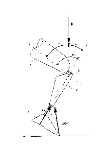
In Figure 6, the prosthesis is schematically
represented in a sitting position. If the user of the
prosthesis is in a sitting position, it is comfortable
if the extension resistance and the flexion resistance
of the resistance device are low, so that the movements
performed during sitting, which generally have a small
extent of movement, can be carried out unimpaired.
To be able to carry out the changes in resistance and a
determination of the state automatically, it is
provided that the inertial angle aT and/or the knee
angle aK are measured. The inertial angle aT of the
upper leg part 1 is measured in relation to the
vertical, which is assumed to be acting in the
direction of gravitational force. In Figure 6, this is
indicated by the gravitational force vector g. Assumed
as the reference variable for the inertial angle aT is
the longitudinal axis of the upper leg part 1, which
passes through the pivoting axis of the prosthetic knee
joint 4. In this case, the longitudinal axis
CA 02780192 2012-05-07
WO 2011/057790
PCT/EP2010/006891
- 18 -
corresponds approximately to the orientation of a
natural upper leg bone and extends substantially
centrally in relation to the upper leg part 1, which is
generally formed as an upper leg shaft.
The knee angle al< lies between the longitudinal extent
of the lower leg part 2 and the longitudinal extent of
the upper leg part 1. Here, too, the longitudinal
extent of the lower leg part 2 passes through the joint
axis of the prosthetic knee joint 4. The knee angle ax
can be calculated from the inertial angle aT of the
upper leg part 1 and the inertial angle ai of the lower
leg part 2, an adapted sign convention being introduced
on account of the calculation of the inertial angles aT
and a, on the basis of the gravitational force vector
g, so that the inertial angle aT of the upper leg part
1 is obtained from the difference between the knee
angle al< and the inertial angle a, of the lower leg part
2.
In addition, the ground reaction force GRF or the axial
force AX that is effective in the longitudinal
direction of the lower leg part 2 is determined, in
order to decide on the basis of the forces present
whether the user of the prosthesis is in a sitting or
standing position.
The ground reaction force GRF is generally reduced
significantly when the user of the prosthesis is
sitting. If, therefore, the ground reaction force GRF
falls below a threshold value, this is a factor in the
assessment as to whether a sitting state applies. If a
great ground reaction force GRF is detected, a standing
position can be assumed, similarly standing up can be
assumed; in both cases, it is appropriate for the
flexion resistance to be increased in order to avoid
CA 02780192 2012-05-07
WO 2011/057790
PCT/EP2010/006891
- 19 -
unwanted collapsing or buckling under a high ground
reaction force GRF.
An abrupt increasing of the resistance after reaching
specific threshold values is often found to be
uncomfortable. It is therefore provided that, after
reaching a threshold value for the ground reaction
force GRF, the resistance is continuously increased.
Typically, the increasing of the resistance would be
carried out between 20% and 30% of the bodyweight, the
reduction between 20% and 10% of the bodyweight. If,
however, there is too great a knee angle al< or inertial
angle aT or if the joint 4 is moved, it can be assumed
that a standing situation does not apply, so that a
reduction of the resistance can be performed, possibly
to an initial resistance. If the upper leg part 1 is in
an inclined position, that is to say in a substantially
horizontal state, so that the inertial angle aT is
between for example 70 and 110 , it is intended that
increasing the resistance should be ruled out. It may
even possibly be that, after a predetermined time has
elapsed, a reduction of the resistance of the
resistance device to below the standing phase
resistance may be performed, since it can then be
assumed that the user of the prosthesis is sitting.
For determining the inertial angle velocity, the
changing of the inertial angle al over time is
determined, so as to obtain an angle velocity to that
can be determined in terms of the amount and direction.
So if there is a specific inertial angle al and a
specific inertial angle velocity mi, it can be assumed
that there is a movement situation, that is to say not
a standing situation in which locking or blocking of
the knee joint would have to be performed.
CA 02780192 2012-05-07
WO 2011/057790
PCT/EP2010/006891
- 20 -
In the case of the present method, it is provided that,
immediately after loading that exceeds a specific
threshold value, a lock comes into effect without any
time delay, so that no separate activation of an
increase in resistance has to be initiated by special
movements that do not correspond to a normal sequence
of movements. A loading signal that represents the
magnitude of the loading is provided by way of the
ground reaction force GRF, the ground reaction force
GRF being sufficient to activate the standing function.
Further variables such as torques or inertial angles
may be used additionally, that is to say to verify the
decision as to whether a standing state or a standing
phase actually applies. With the claimed method it is
possible to lock the knee or some other joint in the
bent position or under bending forces, the locking
advantageously only coming into effect when there is a
slightly bent knee, for example as from a knee bending
of 40 as the knee angle.