Note: Descriptions are shown in the official language in which they were submitted.
CA 02780196 2012-05-07
WO 2011/057840 PCT/EP2010/063843
1
Antenna apparatus and antenna selection method
Background of the invention
For telecommunication in aircrafts, so called direct air-to-ground systems are
used.
Such systems provide a possibility for telecommunication connections from the
air-
craft to a base station on the ground. The Aircraft has a bidirectional
communication
link with the base station located on the ground. The radio signal transmitted
by the
base station in direction towards the aircraft is called the forward link. For
the for-
ward link, the transmission can be made more efficient by techniques like beam-
forming, in which the direction of emission of the radio signal is focussed
and di-
rected towards the receiving aircraft. The advantage is that other aircrafts
which are
located in the outer part of the lobe will receive less interference from such
radio
signals. The base station can additionally transmit with less power than would
be
necessary with omnidirectional transmission schemes.
On the contrary, the aircraft changes often its orientation and altitude.
Hence, high
efforts would be needed to implement a corresponding system into an aircraft
in or-
der to improve the reverse link for transmitting signals from the aircraft to
the base
station in the same way.
Summary of the invention
Embodiments of the invention provide a mobile telecommunication device for
estab-
lishing a telecommunication connection in the radio frequency range with a
base
station.
It is the object of the invention to improve the mobile telecommunication of a
mobile
telecommunication device with a base station.
This invention applies to mobile communications systems like LTE, as defined
in the
corresponding 3GPP standards. The application in other mobile communications
systems is not precluded.
CA 02780196 2012-05-07
WO 2011/057840 PCT/EP2010/063843
2
According to embodiments of the invention the mobile telecommunication device
comprises at least a first and a second antenna, an electromagnetic shield
located
between the first and the second antenna and a logic component. The shield has
a
first side facing the first antenna and a second side facing the second
antenna. The
electromagnetic shield reflects electromagnetic radiation impinging on the
first side
such that at least a portion of the radiation is reflected towards the first
antenna and
the electromagnetic shield reflects electromagnetic radiation impinging on the
sec-
ond side such that at least a portion of the radiation is reflected towards
the second
antenna. The first and the second antenna are adapted to transmit and receive
tele-
communication signals of the same frequency band. The logic component selects
whether the first or the second antenna is used for the reverse link of the
telecom-
munication connection with the base station. Reception of radio signals is
normally
always done by Rx diversity scheme, which automatically combines the received
radio signals of both antennas.
Such mobile telecommunication device may for example be installed in an
aircraft
for establishing a telecommunication connection to a base station located on
the
ground. Therefore, the first antenna is located more to the rear of the
aircraft while
the second antenna is located more to the front of the aircraft. This means,
the first
side of the electromagnetic shield is directed towards the rear of the
aircraft and the
second side of the electromagnetic shield is directed to the front of the
aircraft.
Thus, the first and the second antenna are arranged such that the antenna
pattern
of the first antenna has the highest antenna gain in backward direction of the
air-
craft. The antenna pattern of the second antenna has the highest antenna gain
in
forward direction of the aircraft. This is achieved by locating an
electromagnetic
shield between the first and the second antenna. Another possibility is to
mount two
distinct, separate antennas at locations on the surface of the aircraft that
are located
such that parts of the airplane, e.g. the fuselage itself or a wing or turbine
forms the
shield between the first and second antenna.
The electromagnetic shield prevents that signals transmitted by the first
antenna are
received by the second antenna and vice versa. Additionally, signals being
received
CA 02780196 2012-05-07
WO 2011/057840 PCT/EP2010/063843
3
by the first antenna are received by the second antenna with a high
attenuation and
vice versa.
According to embodiments of the invention the electromagnetic shield is made
of
metal. The essential characteristic of the electromagnetic shield is that it
has to be
electro conductive. Thus, every kind of metal may be used for the
electromagnetic
shield including metal alloys.
According to embodiments of the invention the electromagnetic shield has a
netting
structure, the netting structure comprising metal. By using a netting
structure for the
electromagnetic shield the weight of the shield may be reduced and thereby
also the
weight of the mobile telecommunication device. The weight of the device is
impor-
tant when it is installed in an aircraft.
According to embodiments of the invention the electromagnetic shield is made
of
carbon fibers and metal. Preferably, the electromagnetic shield has a netting
struc-
ture of carbon fibers and metal but also other structures of carbon fibers and
metal
may be applied, for example may the electromagnetic shield be made of carbon
fi-
bers with a metal plating.
According to embodiments of the invention the electromagnetic shield has a
curved
shape. This is advantageous because preferably omni directional antennas are
used for the first and second antenna. Thus, the shape of the electromagnetic
shield
defines the transmission and receiving angle of the first and the second
antenna.
The use of omni directional antennas is advantageous because space can be
saved
by using omni directional antennas in comparison to the use of directional
antennas.
For example, the electromagnetic shield may be curved in two dimensions. This
means the electromagnetic shield has two surrounding elements. A first
surrounding
element surrounds the first antenna while a second surrounding element
surrounds
the second antenna.
Preferably, the electromagnetic shield is curved in all three dimensions. This
means,
the first antenna is surrounded partly in all three dimensions from the first
surround-
CA 02780196 2012-05-07
WO 2011/057840 PCT/EP2010/063843
4
ing element of the electromagnetic shield and the second antenna is surrounded
partly in all three dimensions from the second surrounding element of the
electro-
magnetic shield. In other words, the first and the second surrounding elements
of
the electromagnetic shield have the shape of a quarter sphere. The first and
the se-
cond surrounding elements may also have the shape of a half sphere.
According to embodiments of the invention the electromagnetic shield is an
aircraft
fuselage. This means, that the first antenna is installed in the rear area of
the aircraft
and the second antenna is installed in the front part of the aircraft. The
fuselage
then functions as the electromagnetic shield because usually an aircraft
fuselage
comprises metal. In this case the first antenna is adapted for communicating
with a
base station behind of the aircraft while the second antenna is adapted for
commu-
nication with a base station in front of the aircraft.
According to embodiments of the invention the logic component selects whether
the
first or the second antenna is used based on location information and/or
measure-
ments of signal power, signal quality, timing advance and/or Doppler shift of
the first
and the second antenna. The location information may for example be obtained
from a global navigation satellite system signal, , e.g. global positioning
system
(GPS) or Galileo. Preferably, the first antenna is adapted for communication
with a
base station located on the ground behind the aircraft. The second antenna is
adap-
ted for communication with a base station located on the ground in front of
the air-
craft. From the global navigation satellite system signal, which is usually
always
measured in an aircraft, the logic component knows the position and trajectory
of
the mobile telecommunication device. Further, the mobile telecommunication
device
may comprise a storage comprising a database with base station location
informa-
tion, for example in a data format according to a global navigation satellite
system
standard. This means, the database comprises location information of a
plurality of
base stations in a data format according to the data format of the global
navigation
satellite system being used in the aircraft. Preferably, the logic component
knows
the position and trajectory of the mobile telecommunication device from the
global
navigation satellite system signal and determines by reading from the database
a
base station on the ground being located nearest to the aircraft. Then, the
logic
component selects which antenna is to be used for the transmissions towards
the
CA 02780196 2012-05-07
WO 2011/057840 PCT/EP2010/063843
base station during the establishment of the communication with the base
station. In
case a telecommunication connection is already established, the logic
component
knows the position and trajectory of the mobile telecommunication device from
the
global navigation satellite system signal and determines by reading from the
data-
base the base station on the ground with which the telecommunication
connection is
established.
If the base station is located in front of the aircraft the second antenna is
used for
the reverse link and if the base station is located behind the aircraft the
first antenna
is used for the reverse link.
Other data like the signal power, signal quality, timing advance and/or
Doppler shift
of the first and second antenna are measured by the logic component and consid-
ered for the selection which antenna to use. If, for example the signal power
and the
signal quality of the first antenna is higher than the signal power and the
signal qual-
ity of the second antenna the first antenna is used for the reverse link. From
the tim-
ing advance and the Doppler shift the moving direction of the aircraft
relative to a
base station can be derived. For example, when the Doppler shift is positive
the air-
plane moves towards a base station while, if the Doppler shift is negative,
the air-
plane departs from a base station.
A similar consideration is made for the timing advance. When the timing
advance
decreases the aircraft moves towards a base station while, if the timing
advance
increases, the aircraft departs from a base station. The timing advance may
also be
calculated based on location information derived from global navigation
satellite sys-
tem data.
According to embodiments of the invention the mobile telecommunication device
further comprises a database in a storage, the database comprising location
infor-
mation about a plurality of base stations. The location information is stored
in a data
format readable by the logic component. The location information may for
example
be global navigation satellite system data.
According to embodiments of the invention the logic component receives a
signal
from a base station, the signal being indicative of the antenna to be used for
the re-
CA 02780196 2012-05-07
WO 2011/057840 PCT/EP2010/063843
6
verse link. This is advantageous, when the decision of which antenna is to be
used
is not made by the logic component but by the base station located on the
ground.
If, for example the mobile telecommunication device is connected with the
second
antenna to a base station, while the first antenna measures a higher signal
power
and/or signal quality of another base station, the logic component decides if
a hand-
over shall be performed to the base station measured by the first antenna. The
de-
cision if a handover shall be performed can be based on the location
information
and/or measurements of signal power, signal quality, timing advance and/or
Doppler
shift of the first and the second antenna. If the logic component decides that
a han-
dover shall be performed, a measurement report is sent to the base station
compris-
ing data being important for the handover decision. The base station then
sends a
handover command to the mobile telecommunication device and the handover is
performed according to 3GPP standard. During the handover the antenna of the
mobile telecommunication device may also be changed from the first antenna to
the
second antenna or vice versa.
According to embodiments of the invention the logic component of the mobile
tele-
communication device is interconnected with a Global Navigation Satellite
Service
(GNSS) GPS or GALILEO. Usually, in an aircraft already exists a GNSS device.
The
trajectory can either be delivered by the GNSS device or can be easily
calculated
inside the logic component.
Based on the GNSS data and the locations of the base station stored in a
database
in a storage of the mobile telecommunication device, the logic component
evaluates
whether the aircraft moves towards (TO status) a base station or departs from
a
base station (FROM status). The logic component can autonomously select the an-
tenna according to the following method:
In case of status TO, the second antenna is selected by the logic component.
In case of status FROM, the first antenna is selected by the logic component.
In case of a handover the antenna is switched according to the new status
corre-
sponding to the location of the target base station.
CA 02780196 2012-05-07
WO 2011/057840 PCT/EP2010/063843
7
According to embodiments of the invention the mode for the antenna selection
in
case of transmission of sounding reference symbols remains unchanged compared
to the 3GPP definitions for such sounding.
The decisions taken in the base station to perform such sounding based antenna
switching can however be optimized for the application within direct air to
ground
communications systems by further criteria. It is to be noted that these
criteria can
be applied solitary and in various combinations of one or more of the criteria
below.
Antenna selection is based on the current location and trajectory directly
based on
GNSS data and is performed by the logic component. This is normally done in
air-
planes anyway and the information can be provided to the logic component, or
the
logic component has its own GNSS receiver and calculates the location and
trajec-
tory on its own. Together with the database containing the locations of the
antennas
and their orientations and other radio parameters like maximum transmit power,
the
information can be evaluated, which of the antennas is selected best. In case
the
radio cell with the best expected radio conditions is located in forward
direction, the
front antenna is selected. In case the radio cell with the best expected radio
condi-
tions is located in backward direction, the rear antenna is selected.
The term radio signal power and/or signal quality in the following refers to a
meas-
ured signal power and/or signal quality corresponding to a certain radio cell
known
to the logic component. The used value for the antenna selection process is as-
sumed to be a value that is filtered over time, e.g. by averaging a certain
amount of
measurements or by an I IR filter or sliding window filter etc., to avoid that
inaccura-
cies in the measurement invoke unwanted antenna selection. The same applies to
all other values like timing advance or Doppler shift.
In case of a handover procedure, the radio signal power and/or signal quality
of the
forward link signal of the target radio cell is measured by the mobile
telecommunica-
tion device on both antennas, front and rear. The antenna via which the
reverse link
radio signal is transmitted is selected for the association with the target
radio cell
that has the higher received radio signal strength of the forward link.
Timing advance criteria during a handover procedure:
CA 02780196 2012-05-07
WO 2011/057840 PCT/EP2010/063843
8
Normally the timing advance information is not measured in the mobile
telecommu-
nication device. Instead, the logic component calculates the timing advance
value
based on location information or the timing advance value is delivered to the
logic
component from the base station. Before association to the target radio cell,
no in-
formation from the source base station is available for the timing advance
value of
the target base station. During the association process the timing advance
value is
sent by the target base station to the mobile telecommunication device. How
this
timing advance value is used as an antenna switching criterion is described
for the
case without handover further below.
Doppler criteria, evaluated in the logic component:
If, during handover procedure, especially during the synchronisation to the
target
radio cell, the Doppler shift of the forward link signal of the target radio
cell is posi-
tive - i.e. the frequency measured at the reception by the mobile
telecommunication
device of radio transmissions transmitted from the base station is higher than
the
expected frequency - the second antenna is selected. If the Doppler shift is
nega-
tive, the first antenna is selected.
In case of normal operation, i.e. without a handover in progress:
Radio signal power and/or radio signal quality criteria are evaluated in the
logic
component as follows. The radio signal power and/or the signal quality of the
for-
ward link signal of the current radio cell is measured on both antennas, front
and
rear.
The one antenna is selected for transmission of the reverse link signal, that
has the
higher received radio signal quality and/or signal power of the forward link.
In another aspect the invention relates to a base station apparatus comprising
tele-
communication means for establishing a wireless telecommunication connection
with a mobile telecommunication device. The base station apparatus is adapted
to
receive location information, signal power, signal quality, timing advance
and/or
Doppler shift of a radio signal transmitted from a wireless telecommunication
device.
Based on the location information, signal power, signal quality, timing
advance
and/or Doppler shift the base station apparatus selects whether the first or
the sec-
ond antenna of the wireless telecommunication device shall be used for the
reverse
CA 02780196 2012-05-07
WO 2011/057840 PCT/EP2010/063843
9
link of the telecommunication connection. The base station apparatus transmits
a
signal to the mobile telecommunication device, the signal being indicative of
which
antenna is to be used by the mobile telecommunication device for transmissions
during establishment of the wireless telecommunication connection.
According to embodiments of the invention the base station is adapted to
determine
the current location of a mobile communication device and/or performs measure-
ments of signal power, signal quality, timing advance and/or Doppler shift of
a radio
signal transmitted from the wireless telecommunication device. The location of
the
mobile communication device can be determined for example by triangulation.
In another aspect the invention relates to a system comprising a mobile
telecommu-
nication device and a base station apparatus. The mobile telecommunication
device
comprises at least a first and a second antenna, an electromagnetic shield
located
between the first and the second antenna and a logic component. The shield has
a
first side facing the first antenna and a second side facing the second
antenna. The
electromagnetic shield reflects electromagnetic radiation impinging on the
first side
such that at least a portion of the radiation is reflected towards the first
antenna and
the electromagnetic shield reflects electromagnetic radiation impinging on the
sec-
ond side such that at least a portion of the radiation is reflected towards
the second
antenna. The first and the second antenna are adapted to transmit and receive
tele-
communication signals of the same frequency band. The logic component selects
whether the first or the second antenna is used for the reverse link of the
telecom-
munication connection with the base station.
The base station apparatus comprises telecommunication means for establishing
a
wireless telecommunication connection with a mobile telecommunication device.
The base station apparatus is adapted to receive measurements of global naviga-
tion satellite system data, signal power and/or signal quality of a first and
a second
antenna from the mobile telecommunication device. From the global navigation
sat-
ellite system data the location information can be derived. Based on the
location
information and measurements of signal power, signal quality, timing advance
and/or Doppler shift the base station apparatus selects whether the first or
the sec-
ond antenna of the mobile telecommunication device shall be used for the
reverse
CA 02780196 2012-05-07
WO 2011/057840 PCT/EP2010/063843
link of the telecommunication connection. The base station apparatus transmits
a
signal to the mobile telecommunication device, the signal being indicative of
which
antenna is to be used by the mobile telecommunication device for transmissions
during establishment of the wireless telecommunication connection.
In yet another aspect the invention relates to a telecommunication method for
estab-
lishing a telecommunication connection of a mobile telecommunication device.
The
method comprises the steps of:
determining location information, the location information can for example be
global
navigation satellite system data;
periurrrurry rrredSurerrrern5 ui 5Iyriai power, 5iyrrai yuainy, tllrrlrly
auvdiiud aiiu/ur
Doppler shift of a first and a second antenna of the mobile telecommunication
de-
vice;
selecting whether the first or the second antenna is used for the reverse link
of the
telecommunication connection based on location information and/or measurements
of signal power, signal quality, timing advance and/or Doppler shift of the
first and
the second antenna; and
the transmissions during establishment of a telecommunication connection to a
first
base station apparatus.
Preferably, this method is performed by the logic component in the mobile
telecom-
munication device.
According to embodiments of the invention the mobile telecommunication device
determines location information and measures signal power, signal quality,
timing
advance and/or Doppler shift of the first and the second antenna and the
telecom-
munication device selects whether a first or a second antenna is used for the
re-
verse link of the telecommunication connection. Preferably, the first antenna
is used
for the reverse link of the a telecommunication connection with a base station
being
located behind the mobile telecommunication device and the second antenna is
used for a telecommunication connection with a base station being located in
front
of the mobile telecommunication device.
CA 02780196 2012-05-07
WO 2011/057840 PCT/EP2010/063843
11
According to embodiments of the invention the mobile telecommunication device
determines location information, while the method comprises a further step:
sending the location information to the first base station. The first base
station then
selects whether the first or the second antenna is used for the
telecommunication
connection after having received the location information from the mobile
telecom-
munication device, and/or after having performed measurements of the signal po-
wer, signal quality, timing advance and/or Doppler shift of a radio signal
transmitted
from the mobile telecommunication device. The first base station sends a first
signal
to the mobile telecommunication device, which is indicative of which antenna
is to
be used for the telecommunication connection.
The sent data may be comprised in an extended measurement report compared to
the measurement report according to 3GPP standards. After having received the
above mentioned data, the base station apparatus selects whether the first or
the
second antenna of the mobile telecommunication device is used for the reverse
link
of the telecommunication connection. The base station sends a first signal to
the
mobile telecommunication device, which is indicative of which antenna is to be
used
for the reverse link of the telecommunication connection.
According to embodiments of the invention the base station determines location
in-
formation and/or measures the signal power, signal quality, timing advance
and/or
Doppler shift of a radio signal transmitted from the mobile telecommunication
de-
vice. The method further comprises the step of:
selecting whether the first or the second antenna is used for the
telecommunication
connection after having determined the location information, and/or having
meas-
ured the signal power, signal quality, timing advance and/or Doppler shift of
the ra-
dio signal transmitted from the mobile telecommunication device. The base
station
sends a second signal to the mobile telecommunication device, the second
signal
being indicative of which antenna is to be used for the telecommunication
connec-
tion.
According to embodiments of the invention the base station sets a threshold
for one
of the measured signal properties and transmits this threshold to the mobile
tele-
communication device. The mobile telecommunication device then sends a signal
to
CA 02780196 2012-05-07
WO 2011/057840 PCT/EP2010/063843
12
the base station, when this threshold is reached. Thus, the base station knows
when
a predefined threshold is reached and can then select which antenna of the
base
station shall be used for the reverse link or the base station can decide to
perform a
handover.
According to embodiments the Doppler shift measurement can be performed either
for the reverse or for the forward link.
According to embodiments of the invention the method comprises further the
steps
of:
---- ----------1-1 - ----- -- --- ---------- -- --- -- -- ---------
base station apparatus by transmitting a third signal to the second base
station, the
third signal being indicative of location information, signal power, signal
quality
and/or Doppler shift of the first and the second antenna;
transmitting a fourth signal from the first base station to the mobile
telecommunica-
tion device, the fourth signal being indicative of performing a handover
procedure
from the first base station apparatus to the second base station apparatus.
The handover is then performed according to 3GPP standards. Thus, the logic
component of the mobile telecommunication device decides when a handover shall
be performed based on data being received by the antennas or from a global
navi-
gation satellite system. If the logic component decides to perform a handover
the
relevant data is sent to the base station, which then informs according to
3GPP
standards the target base station of the handover procedure and sends a
handover
command to the mobile telecommunication device when the handover shall be per-
formed.
The handover procedure may also be linked to a switching of the antenna. For
ex-
ample, when the mobile telecommunication device moves away from a first base
station towards a second base station the first antenna may be used for the
com-
munication via the reverse link with the first base station while the second
antenna
is used for the communication via the reverse link with the second base
station.
When the handover from the first base station to the second base station is
per-
formed the logic component also switches from using the first antenna for the
re-
CA 02780196 2012-05-07
WO 2011/057840 PCT/EP2010/063843
13
verse link of the telecommunication connection to using the second antenna for
the
reverse link of the telecommunication connection.
According to embodiments of the invention the mobile telecommunication device
measures the Doppler shift of the signal from the second base station. The
meas-
ured Doppler shift is then transmitted from the mobile telecommunication
device to
the first base station. The first base station transmits the measured Doppler
shift to
the second base station. Thus, the second base station knows about the Doppler
shift of a signal from the second base station to the mobile telecommunication
de-
vice.
Brief description of the drawings
In the following preferred embodiments of the invention will be described, by
way of
example only, and with reference to the drawings in which:
Fig. 1 is a schematic view of an aircraft comprising a mobile telecommunica-
tion device comprising two antennas, and two base stations on the
ground;
Fig. 2 is a schematic view of a mobile telecommunication device with two
antennas and an electromagnetic shield;
Fig. 3 is a schematic view of a mobile telecommunication device with two
antennas and an electromagnetic shield in a housing;
Fig. 4 is a schematic view of a mobile telecommunication device with two
antennas and an alternative electromagnetic shield;
Fig. 5 is a schematic view of a mobile telecommunication device with two
antennas and a curved electromagnetic shield;
Fig. 6 is a schematic view of a mobile telecommunication device with two
antennas and an electromagnetic shield curved in two directions;
CA 02780196 2012-05-07
WO 2011/057840 PCT/EP2010/063843
14
Fig. 7 is a mobile telecommunication device with two antennas and an elec-
tromagnetic shield curved in two directions;
Fig. 8 is a schematic view of two base stations and the corresponding cover-
age area and four moving directions of an aircraft;
Fig. 9 is a diagram of timing advance, Doppler shift, signal quality/power of
the two antennas;
Fig. 10 is a diagram of timing advance, Doppler shift, signal quality/power of
the two antennas for an alternative trajectory of an aircraft;
Fig. 11 is a diagram of timing advance, Doppler shift, signal quality/power of
the two antennas of a third trajectory of an aircraft;
Fig. 12 is a block diagram of a mobile telecommunication device;
Fig. 13 is a block diagram of a system comprising a mobile telecommunication
device and a base station; and
Fig. 14 is a block diagram illustrating a method of antenna switching.
Detailed description
Like numbered elements in these Figs. are either identical elements or perform
the
same function. Elements which have been discussed previously will not
necessarily
be discussed in later Figs. if the function is identical.
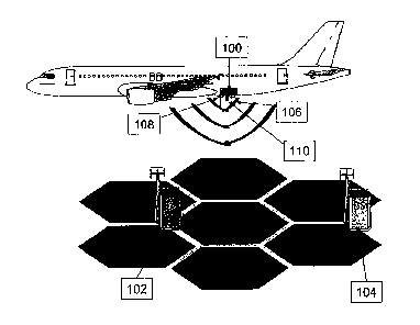
Fig. 1 is a schematic view of a mobile telecommunication device 100 comprising
two
antennas 106 and 108 and one electromagnetic shield 110. The electromagnetic
shield 110 is located between the two antennas 106 and 108. The first antenna
106
is adapted to transmit and receive signals to and from the rear direction of
the air-
craft while the second antenna 108 is adapted to transmit and receive signals
to and
CA 02780196 2012-05-07
WO 2011/057840 PCT/EP2010/063843
from the front direction of the aircraft. Both antennas 106 and 108 are
omnidirec-
tional antennas, the direction of the signals is defined by their orientation
with regard
to the electromagnetic shield 110. Thus, in the moving direction of the
aircraft the
first antenna 106 is located behind the electromagnetic shield 110 and the
second
antenna 108 is located in front of the electromagnetic shield 110.
On the ground are located two base stations 102 and 104. Because both antennas
106 and 108 of the mobile telecommunication device transmit and receive
signals in
the same frequency band, both antennas 106 and 108 could communicate with both
base stations 102 and 104. Because of the electromagnetic shield 110 between
the
antennas 106 and 108 a reverse link of the telecommunication connection is
best
possible of one antenna with one base station. Base station 102 is located
such that
the second antenna 108, which transmits and receives signals to and from the
front
direction of the aircraft can best be used for the reverse link with the base
station
102. Base station 104 is located such that the first antenna 106, which
transmits and
receives signals to and from the rear of the aircraft can best be used for the
reverse
link with base station 104. Reception of radio signals is normally always done
by Rx
diversity scheme, which automatically combines the received radio signals of
both
antennas.
Thus, by measuring signal power, signal quality, Doppler shift and/or timing
advance
of both antennas, the logic component (not depicted) of the mobile
telecommunica-
tion device 100 selects which antenna is best to be used for the reverse link
of a
telecommunication connection. Also global navigation satellite system data
being
recorded in the aircraft anyway can be used by the logic component to
determine
which base station is more likely for having a good telecommunication
connection
with the mobile telecommunication device.
Therefore, the mobile telecommunication 100 device may comprise a storage com-
prising a database with data representing information about the location of
base sta-
tions. The logic component can then compare the location information of the
aircraft
with the data in the database and select the base station to communicate with.
The
location information may for example be data of a global navigation satellite
system,
which is usually always measured in an aircraft. Depending on the selection of
the
CA 02780196 2012-05-07
WO 2011/057840 PCT/EP2010/063843
16
base station also the antenna is selected for the reverse link transmissions.
For a
communication with base station 104 the first antenna 106 would be selected
and
for a communication with base station 102 the second antenna 108 would be se-
lected.
If the aircraft moves on and passes by base station 102 the signal power and
signal
quality received by the second antenna 108 will decrease with a high slope
because
the second antenna 108 is adapted only for communication with base stations
lying
in front of the aircraft. By switching the communication to the first antenna
106, the
telecommunication connection with base station 102 is kept alive and the first
an-
tenna 106 is used for further communication with base station 102.
Fig. 2 shows a schematic view of a mobile telecommunication device comprising
a
first antenna 106 and a second antenna 108 and an electromagnetic shield 110.
Fig.
2a is a cross-sectional side view of the mobile telecommunication device 100.
Fig.
2b is a schematic view from below the mobile telecommunication device 100,
Fig.
2c is a view from above the mobile telecommunication device 100 and Fig. 2d is
a
cross-sectional front view of the mobile telecommunication device 100.
In Fig. 2a it can be seen that the two antennas 106 and 108 are separated by
the
electromagnetic shield 110 and that radiation transmitted by antenna 106 is re-
ceived by antenna 108 with high attenuation and vice versa. Two BNC connectors
112 are adapted for connecting the antennas 106 and 108 to other electrical
ele-
ments not depicted, for example a logic component. In Figs. 2b and c the
electro-
magnetic shield can be seen from below and above. In Fig. 2d the cross-section
of
the electromagnetic shield 110 is depicted. The electromagnetic shield 110 is
at
least as long as the first and the second antenna 106 and 108, preferably it
is
longer. Near the BNC connectors 112, the electromagnetic shield widens in the
cross-section. This is for avoiding or decreasing overlap of the two main
lobes of the
antenna radiation characteristics.
Fig. 3 is a schematic view of two mobile telecommunication devices, each
mobile
telecommunication device comprising two antennas 106 and 108 and an electro-
magnetic shield 110, which widens near BNC connectors 112. One mobile tele-
CA 02780196 2012-05-07
WO 2011/057840 PCT/EP2010/063843
17
communication device stands on its BNC connectors 112. It is to be noted that
the
mobile telecommunication device is installed in an airplane inversely, which
means
with the BNC connectors to the top. The second mobile telecommunication device
in
Fig. 3 lies on its side. In operation the antennas 106 and 108 communicate on
the
same frequency band and signals transmitted or received to and from the first
an-
tenna 106 is shielded by the electromagnetic shield 110 from the second
antenna
108 and signals transmitted or received to or from the second antenna 108 is
shiel-
ded from the first antenna 106 by the electromagnetic shield 110. This results
in the
fact that the first antenna 106 is adapted for communicating in a first
direction while
the second antenna 108 is adapted for communicating in a second direction.
Fig. 4 shows a schematic view of a mobile telecommunication device comprising
a
first antenna 106 and a second antenna 108 and an electromagnetic shield 110.
Fig.
4a is a cross-sectional side view of the mobile telecommunication device 100.
Fig.
4b is a schematic view from below the mobile telecommunication device 100,
Fig.
4c is a view from above the mobile telecommunication device 100 and Fig. 4d is
a
cross-sectional front view of the mobile telecommunication device 100.
In Fig. 4a it can be seen that the two antennas 106 and 108 are separated by
the
electromagnetic shield 110 and that radiation transmitted by antenna 106 is re-
ceived by antenna 108 with high attenuation and vice versa. Two BNC connectors
112 are adapted for connecting the antennas 106 and 108 to other electrical
ele-
ments not depicted, for example a logic component. In Figs. 4b and c the
electro-
magnetic shield can be seen from below and above. In Fig. 4d the cross-section
of
the electromagnetic shield 110 is depicted. The electromagnetic shield 110 is
at
least as long as the first and the second antenna 106 and 108, preferably it
is
longer. Near the BNC connectors 112, the electromagnetic shield widens in the
cross-section. This is for modifying radiation characteristics of the antennas
106 and
108 in different ways.
Fig. 4a shows the curved shape of the electromagnetic shield 110. The
electromag-
netic shield 110 is curved into the direction of antenna 106 such that it
surrounds
antenna 106 in two dimensions. An additional curvature into a third dimension
is
also possible (but not depicted) and part of other embodiments of the
invention.
CA 02780196 2012-05-07
WO 2011/057840 PCT/EP2010/063843
18
Then, antenna 106 is surrounded in all three dimensions of electromagnetic
shield
110 and the radiating angle is limited severely by the electromagnetic shieldl
10.
Thus, a curvature in all three dimensions improves antenna gain and signal
radia-
tion direction.
Fig. 5 is a schematic view of two mobile telecommunication devices, each
mobile
telecommunication device comprising two antennas 106 and 108 and an electro-
magnetic shield 110, which widens near BNC connectors 112. One mobile tele-
communication device stands on its BNC connectors 112. It is to be noted that
the
mobile telecommunication device is installed in an airplane inversely, which
means
with the b and c connectors to the top. The second mobile telecommunication de-
vice in Fig. 5 lies on its side. In operation the antennas 106 and 108
communicate
on the same frequency band and signals transmitted or received to and from the
first antenna 106 is shielded by the electromagnetic shield 110 from the
second an-
tenna 108 and signals transmitted or received to or from the second antenna
108 is
shielded from the first antenna 106 by the electromagnetic shield 110. This
results in
the fact that the first antenna 106 is adapted for communicating in a first
direction
while the second antenna 108 is adapted for communicating in a second
direction.
In Fig. 5 the electromagnetic shield 110 is curved such that it surrounds
antenna
106 in two dimensions. An additional curvature into a third dimension is also
possi-
ble (but not depicted) and part of other embodiments of the invention. Then,
an-
tenna 106 is surrounded in all three dimensions of electromagnetic shield 110
and
the radiating angle is limited severely by the electromagnetic shield110.
Thus, a
curvature in all three dimensions improves antenna gain and signal direction
differ-
ently for the two antennas 106 and 108.
Fig. 6 shows a schematic view of a mobile telecommunication device comprising
a
first antenna 106 and a second antenna 108 and an electromagnetic shield 110.
Fig.
6a is a cross-sectional side view of the mobile telecommunication device 100.
Fig.
6b is a schematic view from below the mobile telecommunication device 100,
Fig.
6c is a view from above the mobile telecommunication device 100 and Fig. 6d is
a
cross-sectional front view of the mobile telecommunication device 100.
CA 02780196 2012-05-07
WO 2011/057840 PCT/EP2010/063843
19
In Fig. 6a it can be seen that the two antennas 106 and 108 are separated by
the
electromagnetic shield 110 and that radiation transmitted by antenna 106 is re-
ceived by antenna 108 with high attenuation and vice versa. Two BNC connectors
112 are adapted for connecting the antennas 106 and 108 to other electrical
ele-
ments not depicted, for example a logic component. In Figs. 6b and c the
electro-
magnetic shield can be seen from below and above. In Fig. 6d the cross-section
of
the electromagnetic shield 110 is depicted. The electromagnetic shield 110 is
at
least as long as the first and the second antenna 106 and 108, preferably it
is
longer. Near the BNC connectors 112, the electromagnetic shield widens in the
cross-section. This is for avoiding interferences.
Fig. 6a shows the curved shape of the electromagnetic shield 110. The
electromag-
netic shield 110 is shaped such that two surrounding elements of the
electromag-
netic shield 110 surround antennas 106 and 108 respectively in two dimensions.
An
additional curvature into a third dimension is also possible (but not
depicted) and
part of other embodiments of the invention. Then, antennas 106 and 108 are sur-
rounded in all three dimensions of electromagnetic shield 110 and the
radiating an-
gle is limited severely by the electromagnetic shield 110. Thus, a curvature
in all
three dimensions improves antenna gain and signal direction.
Fig. 7 is a schematic view of two mobile telecommunication devices, each
mobile
telecommunication device comprising two antennas 106 and 108 and an electro-
magnetic shield 110, which widens near BNC connectors 112. One mobile tele-
communication device stands on its BNC connectors 112. It is to be noted that
the
mobile telecommunication device is installed in an airplane inversely, which
means
with the b and c connectors to the top. The second mobile telecommunication de-
vice in Fig. 7 lies on its side. In operation the antennas 106 and 108
communicate
on the same frequency band and signals transmitted or received to and from the
first antenna 106 is shielded by the electromagnetic shield 110 from the
second an-
tenna 108 and signals transmitted or received to or from the second antenna
108 is
shielded from the first antenna 106 by the electromagnetic shield 110. This
results in
the fact that the first antenna 106 is adapted for communicating in a first
direction
while the second antenna 108 is adapted for communicating in a second
direction.
CA 02780196 2012-05-07
WO 2011/057840 PCT/EP2010/063843
In Fig. 7 the electromagnetic shield 110 is curved such that two surrounding
ele-
ments of the electromagnetic shield 110 surround antennas 106 and 108 respec-
tively in two dimensions. An additional curvature into a third dimension is
also pos-
sible (but not depicted) and part of other embodiments of the invention. Then,
an-
tennas 106 and 108 are surrounded in all three dimensions of electromagnetic
shield 110 and the radiating angle is limited severely by the electromagnetic
shield 110. Thus, a curvature in all three dimensions avoids or decreases
overlap of
the two main lobes of the antenna radiation characteristics and further
improves an-
tenna gain and signal direction differently for the two antennas 106 and 108.
Fig. 8 is a diagram of four exemplary airplane trajectories 800, 802, 804 and
806.
Each trajectory leads through a first cell 808 and a second cell 810. First
cell 808 is
served by first base station 102 and second cell 810 is served by second base
sta-
tion 104. On trajectory 800 the aircraft flies directly over first base
station 102 and
afterwards over the second base station 104. Following trajectory 802 the
aircraft
flies first through cell 808 served by base station 102 and afterwards through
cell
810 served by base station 104. Trajectory 804 leads through the area in
between
the two base stations 102 and 104 through an overlapping area of the two cells
808
and 810. Trajectory 806 is a circle trajectory, which is performed for example
by an
aircraft waiting for landing permission. The trajectory 806 lies completely in
the sec-
ond cell 810 served by the second base station 104.
Fig. 9 shows the timing advance, the signal quality and power of the rear
antenna,
the Doppler shift and the signal quality and power of the front antenna of an
aircraft
following trajectory 800 depicted in Fig. 8. Trajectory 800 passes by directly
over
base stations 102 and 104. It is to be noted that from every data depicted in
Fig. 9
the point when base station 102 or base station 104 are traversed can be deter-
mined.
For example, the timing advance decreases when the aircraft moves towards a
base station, the timing advance increases when the aircraft departs from a
base
station. The Doppler shift is positive when moving towards a base station and
it is
negative when departing from a base station. The signal quality and power from
the
CA 02780196 2012-05-07
WO 2011/057840 PCT/EP2010/063843
21
rear antenna is lower than the signal quality and power from the front antenna
when
moving towards a base station and vice versa when departing from a base
station.
Fig. 10 is a diagram of signal quality and power of the rear and front
antenna, the
timing advance and the Doppler shift for an aircraft being on trajectory 802
depicted
in Fig, 8. The Doppler shift is positive but decreasing in contrast to Fig. 9
when the
aircraft shortens the distance between itself and the base station 102 or 104.
Be-
cause trajectory 802 does not lead directly over the base stations 102 and
104, the
Doppler shift does not shift immediately when being near base station 102. The
Doppler shift is constantly decreasing, in a region near base stations 102 or
104
rapidly decreasing in comparison to the rest of the trajectory. The timing
advance
develops similar to Fig. 9 but with a lower slope because trajectory 802 does
not
lead directly over base stations 102 and 104. Signal quality and power of the
rear
and front antenna also develop similar to Fig. 9. Again one can easily
determine
from the measured signals when the aircraft passes by a base station and when
the
telecommunication connection is to be switched from one antenna to the other
one.
For example the Doppler shift becomes negative when passing by a base station
and the rear antenna shall be used, the timing advance increases when the rear
antenna shall be used and decreases when the front antenna shall be used. For
deciding based on the signal quality and/or the signal power a simple
comparison of
the two values of the rear antenna with the two values of the front antenna
makes
obvious which antenna is to be used best.
Fig. 11 shows measured data from an aircraft following trajectory 804 depicted
in
Fig. 8. Trajectory 804 leads only through the area which is covered by both
base
stations 102 and 104. The aircraft passes by base stations 102 and 104 at the
same
time. Throughout the whole trajectory timing advance, signal quality/power of
the
rear antenna, Doppler shift and signal quality/power of the front antenna are
meas-
ured. The Doppler shift again is constantly decreasing and becomes negative
when
the aircraft has passed by the base stations 102 and 104, the signal quality
and the
signal power of the rear antenna increase with a high slope when approaching
the
base stations 102 and 104 and decreases when departing from the base stations
102 and 104. The signal quality and the signal power of the front antenna
increase
with a high slope when departing from the base stations 102 and 104. The
timing
CA 02780196 2012-05-07
WO 2011/057840 PCT/EP2010/063843
22
advance decreases when approaching base stations 102 and 104 and increases
when departing from base stations 102 and 104. Again, one can easily see, as
in
Figs. 9 and 10, how to determine when to switch the antenna to be used for the
ra-
dio frequency telecommunication.
Fig. 12 is a block diagram of a mobile telecommunication device 100 comprising
a
first antenna 106, a second antenna 108, an electromagnetic shield 110, a
logic
component 1000 and a storage 1002. In operation, the first and the second
antenna
106 and 108 are adapted to communicate on the same radio frequency band. They,
for example communicate with a base station apparatus. The logic component is
adapted to receive signals from the first and the second antenna 106 and 108
and
to read from storage 1002. Further, logic component 1000 determines, which an-
tenna shall be used for the reverse link of the telecommunication connection.
Fig. 13 shows a system comprising base station 1100 and mobile telecommunica-
tion device 100. The mobile telecommunication device 100 comprises first
antenna
106, second antenna 108, electromagnetic shield 110, logic component 1000 and
storage 1002. Storage 1002 may comprise a database being indicative of
locations
of base stations.
Base station 1100 comprises transmission and receiving means 1102 for communi-
cation with mobile telecommunication device 100 and a processor 1104. In opera-
tion, the mobile telecommunication device transmits data being indicative for
switch-
ing antenna or performing a handover to another base station via first antenna
106
or second antenna 108 to the transmission and receiving means 1102 of the base
station 1100. Processor 1104 then reads the received data and determines if a
handover shall be performed or if the other antenna currently not used shall
be used
for the reverse link of the telecommunication connection.
Fig. 14 is a block diagram of a method, the method comprising the steps of:
Si: performing measurements of global navigation satellite system data, signal
power, signal quality, timing advance and/or Doppler shift of a first and a
second
antenna of the mobile telecommunication device;
CA 02780196 2012-05-07
WO 2011/057840 PCT/EP2010/063843
23
S2: selecting whether the first or the second antenna is used for the
telecommunica-
tion connection based on measurements of signal power, signal quality, timing
ad-
vance and/or Doppler shift of the first and the second antenna; and
S3: establishing a telecommunication connection to a first base station
apparatus.
CA 02780196 2012-05-07
WO 2011/057840 PCT/EP2010/063843
24
List of reference numerals
------------------------------------
100 Mobile telecommunication device
102 First base station
104 Second base station
106 First antenna
108 Second antenna
110 Electromagnetic shield
800 Trajectory
802 Trajectory
804 Trajectory
806 Trajectory
808 First cell
810 Second cell
1000 Logic component
1002 Storage
1100 Base station
1102 Transmission and receiving means
1104 processor