Note: Descriptions are shown in the official language in which they were submitted.
CA 02780360 2012-06-20
MODULAR WALLS WITH INCORPORATED PLANTERS
BACKGROUND OF THE INVENTION
The Field of the Invention
This invention relates to systems, methods, and apparatus for adding live
plants to a wall inside of a building. More specifically, the systems,
methods, and
apparatus relate to incorporating live plants into a wall module.
Background and Relevant Art
Office workers often spend approximately eight hours a day or more working
in an office or cubical. Such workspaces can be dull and aesthetically
unpleasing, and
lead to reduced production. It is known that adding plants to a workspace can
increase the attractiveness of the workspace.
In addition to the foregoing, high levels of pollutants common in building
interiors can contribute to illness and lower rates of productivity in the
workplace. To
address toxic elements circulating in the air and render it fit for human use,
most
buildings condition air through a heating, ventilation and air conditioning
(HVAC)
system. Conditioning air requires energy, further contributing to greenhouse
gas
production and the cost of building operations. Plant landscapes are known to
remove
harmful environmental toxins found in building interiors, and can lighten the
load of
the HVAC system by removing many of these pollutants, resulting in less energy
use
in buildings.
Unfortunately, the addition of live plants to a workspace can present a number
of drawbacks. For example, typical live plants require regular watering.
Hence, care
and regular watering of such plants may result in interruptions to the worker,
which
may be unexpected and/or unwanted. Additionally, common plant watering
practices
may lead to spills and mess that can produce hazardous environment as well as
unpleasant appearance of the individual space. The challenges and problems
relevant
to a single live plant may drastically increase with the number of live plants
that may
require attention and care.
Living walls (walls which incorporate live plants within or attached to the
wall
with a mechanism to provide water to such plants) are typically vertical
living plant
systems that are typically fixed in place. The behavior of modular and
adaptive wall
CA 02780360 2012-06-20
2
systems has historically been in conflict with the core nature of these living
wall
systems. Furthermore, in the event occupants wish to reconfigure their
individual
offices, conventional living walls may present an obstacle to such
rearrangement as
conventional living walls are immutable.
Accordingly, there are a number of disadvantages in conventional systems that
incorporate live plants into the wall modules that can be addressed.
BRIEF SUMMARY OF THE INVENTION
Implementations of the present invention provide systems and apparatus for
incorporating live plants on support surfaces, such as walls, wall segments,
and wall
modules inside a building. Such system can provide pleasing aesthetic and
improved
surroundings for an occupant of an individual space within the building.
Moreover,
the system also can help to reduce volatile organic compounds (i.e., various
pollutants) that may be present in the air of building, thereby providing a
healthier
environment for the occupants. In one or more implementations, the system and
apparatus also can include a watering system, which can optimize water
delivery to
the live plants.
At least one implementation includes a wall module incorporating live plants.
The wall module is configured to selectively attach to one or more additional
wall
modules to form a reconfigurable partition to divide an interior space. Such
wall
module includes one or more upright supports configured to couple the wall
module
to another wall module and one or more cross-members secured to the one or
more
upright supports. The wall module also includes a panel configured to be
coupled to
one or more of the upright supports and the cross-members and one or more
planters
secured to the panel. The one or more planters are sized and configured to
contain
one or more live plants. Furthermore, the wall module includes a watering
system
configured to supply water to the one or more planters.
One or more implementations include a reconfigurable modular wall system
incorporating one or more live plants. The reconfigurable modular wall system
is
configured to divide an interior space and is also configured to be easily
assembled,
reconfigured, and disassembled. Such reconfigurable modular wall system
includes a
plurality of wall modules selectively secured together to form a partition and
one or
more planters configured to contain live plants. The planters are configured
to be
CA 02780360 2012-06-20
3
selectively coupled to a wall module of the plurality of wall modules at any
of a
plurality of available locations on the wall module. Additionally, the
reconfigurable
modular wall system includes a first watering tray selectively mounted on the
wall
module, wherein the first watering tray is mounted below the one or more
planters
and a water delivery system configured to deliver water from the first
watering tray to
the one or more planters. Furthermore, a water supply system is connected to
the first
watering tray and is configured to supply water into the first watering tray.
At least one other implementation includes an indoor live plant system
configured to be mounted on a support surface and to supply water to live
plants.
io Such system includes a panel and one or more planters configured to contain
live
plants, the one or more planters coupled to the panel. The system also
includes a first
watering tray coupled to the panel and a second watering tray coupled to the
panel,
wherein the second watering tray is coupled to the panel below the first
watering tray.
Moreover, the system includes a connection pipe interconnecting the first
watering
tray and the second watering tray and configured to provide communication of
water
between the first and the second watering trays. The system also includes a
supply
pipe connected to the first watering tray and configured to supply water into
the first
watering tray.
Additional features and advantages of exemplary implementations of the
invention will be set forth in the description which follows, and in part will
be
obvious from the description, or may be learned by the practice of such
exemplary
implementations. The features and advantages of such implementations may be
realized and obtained by means of the instruments and combinations
particularly
pointed out in the appended claims. These and other features will become more
fully
apparent from the following description and appended claims, or may be learned
by
the practice of such exemplary implementations as set forth hereinafter.
BRIEF DESCRIPTION OF THE DRAWINGS
In order to describe the manner in which the above-recited and other
advantages and features of the invention can be obtained, a more particular
description of the invention briefly described above will be rendered by
reference to
specific embodiments thereof which are illustrated in the appended drawings.
For
better understanding, the like elements have been designated by like reference
CA 02780360 2012-06-20
4
numbers throughout the various accompanying figures. Understanding that these
drawings depict only typical embodiments of the invention and are not
therefore to be
considered to be limiting of its scope, the invention will be described and
explained
with additional specificity and detail through the use of the accompanying
drawings in
which:
Figure I illustrates a perspective view of an indoor live plant system in
accordance with one implementation of the present invention;
Figure 2 illustrates a cross-sectional view of the indoor live plant system of
Figure 1 taken along the line 2-2 of Figure 1;
Figure 3 illustrates a perspective exploded view of a watering system in
accordance with one implementation of the present invention;
Figure 4 illustrates a perspective view of two wall modules each incorporating
an indoor live plant system in accordance with one implementation of the
present
invention; and
Figure 5 illustrates a cross-sectional view of a portion of the indoor live
plant
system of Figure 4 taken along the line 5-5 of Figure 4.
DETAILED DESCRIPTION OF THE PREFERRED EMBODIMENTS
Implementations of the present invention provide systems and apparatus for
incorporating live plants on support surfaces, such as walls, wall segments,
and wall
modules inside a building. Such system can provide pleasing aesthetic and
improved
surroundings for an occupant of an individual space within the building.
Moreover,
the system also can help to reduce volatile organic compounds (i.e., various
pollutants) that may be present in the air of building, thereby providing a
healthier
environment for the occupants. In one or more implementations, the system and
apparatus also can include a watering system, which can optimize water
delivery to
the live plants.
In particular, one or more implementations include one or more container
components to hold one or more plants, and one or more watering components to
provide water to the plants. The container and watering components can attach
to a
modular wall. In at least one implementation, the watering components include
one
or more trays or troughs to act as reservoirs for supplying water to the
container
components. A user or designer can adapt the modular live plant system by
adding,
CA 02780360 2012-06-20
subtracting, or realigning the components on a modular wall, or by moving the
components to another modular wall.
In alternative or additional implementations, a modular live plant system or
modular living wall incorporates the container and watering components within
the
5 panels of a modular wall system rather than as separate components that
attach to the
panels. In these implementations, the panels can interconnect in various
configurations within the environment of the modular live plant system.
As a preliminary matter, frequent reference is made herein to modular walls or
wall modules. A modular wall is intended to mean any wall that facilitates the
reconfiguration of attachments such as the container and watering components
of the
present invention. A modular wall may comprise a special purpose wall that is
specifically configured to receive attachments of a particular configuration.
A
modular wall, however, may be a standard flat wall that is rendered modular by
the
fact that the attachments are configured to be mounted (and remounted) to the
wall in
a non-permanent manner such as to enable the reconfiguration (e.g. addition,
removal,
movement to another position) of the attachments. Accordingly, the present
invention
applies to many different types of modular walls and is not limited to any
particular
modular wall such as those shown in the Figures.
In at least one implementation, the indoor live plant system can allow the
occupants of the building to secure live plants to one or more walls within
the
building. In particular, the indoor live plant system can provide occupants
with
ability to create various arrangements and configurations of one or more
planters and,
consequently, of the live plants within the planters on one or more walls in
the
building. Furthermore, the indoor live plant system can include a watering
system
that can supply water to the live plants at various positions and in various
arrangements on the wall. Accordingly, the indoor live plant system can
sustain live
plants, which may have substantially any desired positions and/or arrangement.
Additionally or alternatively, the planters of the indoor live plant system
can
incorporate one or more mounting elements (e.g., protrusions/protruding
elements,
recessed elements, etc.) that may allow an installer to reposition the
planters. In
particular, the planters can include one or more mounting elements that can
connect to
a panel, and which can allow the installer to easily remove and/or reposition
one or
CA 02780360 2012-06-20
6
more planters on the walls or wall module. For example, the panel may remain
stationary on the wall, and the installer can reposition and/or rearrange the
planters
with respect to the stationary panel.
In one or more implementations, the indoor live plant system also can include
a single planter or multiple planters, each of which may house one or more
live plants,
and which may cover all or a portion of a particular wall or wall module. For
instance, as illustrated in Figure 1, an indoor live plant system 100 can
include one or
more container components configured to house a live plant, such as planters
110.
The indoor live plant system 100 can also include a watering system 120. The
watering system 120 can deliver water to the planters 110, thereby supplying
water to
the live plants that may be contained within the planters 1 10. The indoor
live plant
system 100 can further include a panel 160. The panel 160 can support the
planters
110 and the watering system 120. As explained in greater detail below, the
panel 160
can attach to a wall, a support surface, a modular wall panel, or comprise a
modular
wall panel.
The watering system 120 can include one or more watering components, such
as watering trays 130 (e.g., watering trays 130a, 130b, 130c, etc.). The
watering trays
130 can contain and/or channel the water delivered from a water source. The
term
"water," as used herein, refers to any substance in liquid or semi-liquid from
(e.g.,
gel), which may support life of the live plants, and which includes but is not
limited to
water, water-based solutions, fertilizer, etc. The watering system 120 also
can include
one or more hoses or connection pipes 140, which can deliver the water to and
from
the watering trays 130. Furthermore, in at least one implementation, the
watering
system 120 can include a water delivery system 150 that can deliver the water
from
the watering trays 130 into one or more planters 110.
In one or more implementations, the watering system 120 can receive water
from a water supply system (e.g., plumbing system within the building).
Moreover,
the watering system 120 can incorporate a controller, which can activate the
water
supply system, thereby supplying water into the watering system 120 at
predetermined time intervals. Additionally or alternatively, the occupant of
the
building can manually add water to the watering system 120. Whether added
manually or in an automated fashion, the water can enter the watering system
120 at a
CA 02780360 2012-06-20
7
single point and can subsequently flow into the various watering trays 130
comprising
the watering system 120. In other words, the watering system 120 can
distribute the
water from a single fill point, where the water can enter one or more of the
watering
trays 130, such that the desired watering trays 130 as well as planters 110
within the
indoor live plant system 100 can receive water.
In at least one implementation, one or more portions of the watering system
120, such as the watering trays 130, are located below the planters 110. For
example,
the watering tray 130a can couple to the support surface below a first row of
one or
more planters 110. Accordingly, the water delivery system 150 can deliver
water
upward from the watering trays 130 into the planters 110. In particular, the
water
delivery system 150 can include a wick, which can absorb water present in the
watering trays 130 (e.g., by capillary action) and deliver the water into the
planters
110.
Additionally or alternatively, one or more portion of the watering system 120
can couple to the support surface above one or more planters 110. For
instance, the
watering trays 130 can include one or more perforations that may allow water
to flow
or drip down into one or more planters 110. Furthermore, the watering trays
130 also
can include a sponge-like material covering the perforations. Accordingly, the
sponge-like material may absorb the water that enters the watering trays 130
and may
permit only a regulated amount of water to pass through the perforations in
the
watering trays 130.
Referring now to Figure 2 various components and features of the planters
110, watering trays 130, and panel 160 are shown and described in greater
detail. For
example, Figure 2 illustrates that the panel 160 comprise one or more mounting
channels 210a, 210b. The mounting channels 210a can comprise L-shaped bodies
that extend laterally away from the panel 160 and longitudinally upward as
shown in
Figure 2.
Similar to the mounting channels 210a, the mounting channels 210b can
comprise L-shaped bodies. In particular, the mounting channels 210b can extend
laterally away from the panel 160 and generally longitudinally downward. In
addition
to the mounting channels 210a, 210b, the panel 160 can further include one or
more
standoffs. As show by Figure 2, the standoff 220 can comprise a ridge that
extending
CA 02780360 2012-06-20
8
from the bottom of a mounting channel 210a generally downward. The mounting
channels 210a, 210b and the standoffs 220 can corporate with corresponding
features
to couple the planters 110 and the watering system 140 to the panel 160.
As shown by Figure 2, the planter 110 can comprise a bottom surface 112
bounded by a front wall 113, opposing side walls 114, and a rear wall 115. The
walls
113, 114, 115 of the planter 110 can define an interior space 116 for
receiving one or
more live plants and/or a potting medium. The planters 110 can have numerous
external and internal shapes and dimensions, as desired by the installer or
suitable for
a particular building environment. More specifically, the planters 110 can
have a
to substantially rectangular outside shape as shown by Figure 2. In
alternative
implementations, the planters 110 can comprise square, circular, oval, or
complex
shapes depending upon a desired aesthetic.
In any event, in one or more implementations the rear surface 115 of the
planter 110 can be oriented at an obtuse angle relative to the bottom surface
112 as
shown in Figure 2. Thus, when mounted on a substantially vertical support
surface, a
bottom surface 112 of the planters 110 may form an acute angle with the
support
surface. Thus, the planters 110 can present a greater portion of the live
plants to a
viewer of the indoor live plant system 100.
[0001] Additionally, the planters 110 can have at least one curved wall,
which may create a pleasing aesthetic for the viewer. For example, a front
wall 113
of one or more planters 110 can have a curved surface. Thus, the installer or
occupant
can arrange the planters 110 on the support surface or the panel 160 to form
various
shapes (e.g., the planters 110 can form a wave-like shape).
[0002] In addition to the foregoing, Figure 2 illustrates that the front wall
113
has approximately the same size as the bottom surface 112 and the rear wall
115. In
alternative implementations, the front wall 113 can have a low-profile or
otherwise be
smaller (or shorter) than the bottom surface 112 and the rear wall 115. A low-
profile
front wall 113 can allow greater visibility of any plants inside the planter
110 or
otherwise allow such plants to conceal the planter 110 to a great extent.
[00031 The planter 110 can optionally include one or more pegs 117. The
pegs 117 can comprise supports extending from the bottom surface 112 generally
upward into the interior space 116 of the planter 110. The pegs 117 can
provide
CA 02780360 2012-06-20
9
support to a live plant. Figure 2 further illustrates that the planter 110 can
include one
or more holes 118 extending through the bottom surface 112. The holes 118 can
allow a water delivery system 150 to transport or otherwise provide water to
plants in
the planter 110 as explained in greater detail below.
[0004] As described in greater detail below, the planter 110 can include one
or
more features or components that allow for selective connection to the panel
160.
The ability to removably connect the planter 110 to the wall 160 can allow a
user the
ability to easily move, remove, and/or reconfigure the design of a live plant
system
100. One will appreciate that a user may desire to move or reconfigure the
live plant
system 100 to change the aesthetic of the live plant system 100 or to
compensate for
reconfiguration of a wall, room, office, or cubical to which the live plant
system 100
is mounted.
[0005] For example, the planter 110 can include mounting elements 170 for
selectively securing the planter 110 to the panel 160. As shown by Figure 2,
the
mounting elements 170 can include one or more mounting hooks 190 and one or
more
stays 200. The mounting hooks 190 can support the planter 110 in a hanging
position
on the panel 160 (or on a support surface) that contains a channel that can
accept the
mounting hooks 190. The mounting hooks 190 can comprise L-shaped bodies. In
particular, the mounting hooks 190 can extend laterally away from the planter
110 and
longitudinally downward. Thus, as shown by Figure 2, the mounting hook 190 can
connect to the mounting channel 210a to hold and support the planter 110 on
the
panel 160.
[0006] The mounting elements 170 of the planter 110 can optionally include
one or more stays 200. The stays 200 can comprise protrusions that extend
generally
perpendicularly away from the back wall of the planter 110. The stays 200 can
cooperate with the panel 160 to provide separation between the panel 160 and
the
planters 110 and/or provide a desired orientation of the planter 110 relative
to the
panel 160 as explained in greater detail below. The stays 200 of the planters
110 can
abut the standoffs 220 of the panel 160 to create a separation between the
planters 110
and a portion of the panel 160 and/or dictate the angle at which the planter
110 is
oriented relative to the panel 160.
CA 02780360 2012-06-20
[0007] More specifically, the stays 200 of the planters 110 and the standoffs
220 can cooperate to determine the angle of the planters 110. In other words,
location
of an interface between the stays 200 and the standoffs 220 can set the angle
formed
between the back wall of the planters 110 with respect and the support
surface. Thus,
5 for example, incorporating various planters 110 that have differently sized
stays 200
can create the indoor live plant system 100 with planters 110 disposed at
different
angles, which may produce a further appealing aesthetic.
[0008] Similar to the planter(s) 110, the watering trays 130 can also
removably couple to the panel 160. In particular, the watering trays 130 can
10 incorporate mounting elements 180, such as one or more mounting hooks 230,
one or
more stays 240, and/or one or more snaps 250. The mounting hooks 230 can
comprise L-shaped bodies. In particular, the mounting hooks 230 can extend
laterally
away from a back wall of the watering tray 130 and longitudinally downward.
Thus,
as shown by Figure 2, the mounting hooks 230 can connect to the mounting
channel
210a to hold and support the watering tray 130 on the panel 160.
[0009] Additionally, the watering tray 130 can have one or more stays 240.
The stays 240 can comprise protrusions that extend laterally away and/or
longitudinally downward from the back surface of the watering tray 130. The
stays
240 can abut the outer surface of the mounting channel 210b to provide
additional
stability to the watering trays 130. Location of an interface between the
stays 240 and
the mounting channel 210b can help define the angle formed by a back wall of
the
watering trays 130 and the panel 160. Accordingly, the angle of the watering
trays
130 can vary based on the location of the interface between the stays 240 and
mounting channel 210b.
[0010] In at least one implementation, the watering trays 130 also can include
one or more snaps 250 that can fit into the mounting channels 210b. The snaps
250
can comprise a flexible arm extending from either the bottom surface or back
wall of
the watering tray 130. The snaps 250 can deform about and into the mounting
channels 210b. Additionally or alternatively, the snaps 250 (as well as other
mounting elements described above) can slide into the mounting channels 210b.
Furthermore, the snaps 250 can force the stays 240 against the mounting
channels
CA 02780360 2012-06-20
11
210b. In particular, the stays 240, the snaps 250, and/or the standoffs 220b
may
comprise of flexible, resilient material that may have spring-like properties.
Thus, when the stays 240 presses against the standoffs 220b, the stays 240
and/or standoffs 220b can deflect and remain in contact one with the other,
which
may provide additionally stability to the watering trays 130. Such stability
may have
particular advantage when the water enters and/or flows within the watering
trays
130. Accordingly, the stays 240, snaps 250, and standoffs 220b can cooperate
to
prevent shifting or undesirable movement of the watering trays 130, thereby
potentially preventing spills or other incidents that may result from
undesirable
movements of the watering trays 130.
As described above, the panel 160 can have various features that can allow the
installer to selectively and removably secure the planters 110 and at least a
part of the
watering system 120 to the panel 160. For example, the panel 160 can have
channels
210 that can accept mounting elements 170, 180 of the planters 110 and
watering
trays 130. Alternatively, panel 160 can have no mounting features, and the
planters
110 and/or watering system 120 can mount directly to such panel with screws or
other
fasteners. It should also be noted that panel 160 can have various
configurations,
designs, and styles (e.g., material, color, thickness, size, shape, etc.).
Accordingly, the
installer can assemble the wall module incorporating live plants 370 based on
the
particular requirements or desires of the occupant, using one or more
appropriate
panels 160.
In one or more implementations, as described above, the watering trays 130
can couple to the support surface and/or to the panel 160 below the planters
110.
Furthermore, the indoor live plant system 100 can incorporate a space 260,
which can
separate the bottom wall of the planters 110 from a top wall of the watering
trays 130.
Incorporating the space 260 into the indoor live plant system 100 (between the
planters 110 and the watering trays 130) also can allow a manufacturer of the
planters
110 and/or watering trays 130 to relax production tolerances thereof. In other
words,
the space 260 can provide clearance between the planters 110 and watering
trays 130
that can accommodate manufacturing dimensional deviations and facilitate
installation of the indoor Iive plant system 100.
CA 02780360 2012-06-20
12
The watering trays 130 can include one or more sidewalls that forms a
substantially normal, acute, or obtuse angle with a bottom wall thereof. In at
least one
implementation, the sidewall of the watering trays 130 that incorporates
mounting
elements 180 can form a normal or an acute angle with the bottom wall of the
watering trays 130. Thus, for example, the water contained within the watering
trays
130 can remain proximate to an intake position of the water delivery system
150.
Additionally, as described above, a sidewall of the planters 110 can form an
angle (e.g., 90 , acute, or obtuse) with respect to the bottom surface
thereof; hence,
the planters 110 can form, for example, an acute angle between the bottom
surface
112 thereof and the support surface and/or panel 160. Accordingly, in one or
more
implementations, the bottom surface 110 of the planters 110 and the bottom
wall of
the watering trays 130 can form an acute angle with respect to each other.
Alternatively, the bottom walls of the planters 110 and watering trays 130 can
form an
obtuse angle or can be parallel with respect to one another.
The watering trays 130 also can have the top wall 134 that forms an acute
angle with respect to the bottom wall 132 of the watering trays 130. Thus, the
top
wall 134 of the watering trays 130 and the bottom surface 112 of the planters
110 can
be substantially parallel with one another. Hence, the space 260 between the
planters
110 and the watering trays 130 can be approximately the same throughout the
indoor
live plant system 100, which can enhance the aesthetic of the indoor live
plant system
100. Additionally, the shape or curvature of a front-facing surface (or a
front wall)
135 of the watering tray 130 can match the shape and/or curvature of the front
wall of
the planters 110 disposed above and/or below such watering tray 130.
As described above, the watering system 120 can incorporate a water delivery
system 150. In particular, the planters 110 can include an opening or hole 118
in the
bottom surface 112 that can provide the water delivery system 150 with access
to the
interior space 116 of the planter 110. The water delivery system 150 can
channel
water from the watering trays 130 into the planters 110. For example, the
opening or
hole 118 in the bottom surface of the planters 110 can accept the water
delivery
system 150. Additionally, the watering system 120 can include water delivery
system
150 that has a location proximate to the sidewall of the watering trays 130,
which
incorporates the mounting elements 180.
CA 02780360 2012-06-20
13
In at least one implementation, the opening or hole 118 in the bottom surface
1 l2 of the planter 110 and at least a portion of the water delivery system
150 can
cooperate to prevent any contents of the planters 110 from exiting through the
hole
118 in the bottom surface 112 of the planter 110. For example, in addition to
live
plants, the planters 110 can include potting medium, such as soil or soilless
medium
designed for cultivation of horticultural plants. Thus, the planters 110 can
have
clearance between the hole 118 in the bottom surface 112 and the water
delivery
system 150 that is smaller than the particles of the potting medium.
Furthermore, the
water delivery system 150 also can have an interference fit with the hole 118
in the
bottom surface 112 of the planters 110, thereby preventing the potting medium
from
exiting the planters 110.
Moreover, such interference fit (as well as other methods of sealing the water
delivery system 150 within the hole 118 in the bottom surface 112 of the
planters 110)
also can secure the water delivery system 150 to the planters 110.
Accordingly, the
installer or occupant can remove the planters 110 from the support surface
and/or
panel 160 together with the water delivery system 150. Maintaining the water
delivery system 150 secured to the planters 110 while the planters 110 are
disconnected from the support surface and/or panel 160 also can help maintain
the
potting medium within the planters 110. More specifically, such configuration
can
help maintain the potting medium within the planters 110 while the occupant
relocates, repositions, and/or rearranges various planters 110.
The top wall 134 of the watering trays 130 also can include an opening
therein, which can provide access to the water delivery system 150 that can
deliver
water from the watering trays 130 into the planters 110. In particular, the
top wall
134 of the watering trays 130 can accommodate the water delivery system 150.
In one or more implementations, the water delivery system 150 can comprise a
wick. The wick 150 can comprise a cellulose sponge material or other porous
formed
materials. For example, the wick 150 can comprise formed resin composites,
sponge
materials, cellulose materials, or fibrous materials. In any event, when in
contact with
water in the watering tray 130, the wick 150 can transport water by absorption
and/or
capillary action from the watering tray 130 along its length and into the
planter 110.
Soil or other growing medium in the planter can diffuse the water into the
plant root.
CA 02780360 2012-06-20
14
One will appreciate that the water delivery system (e.g., wick 150) can allow
the watering tray 130 and planter 110 to be separated. This can prevent direct
contact
between the planter 110 (and the associated plant and soil therein) and the
water.
Thus, the wick 150 can help prevent the planting medium from absorbing excess
water, with adverse consequences for the respective plant.
Figures 1-2 illustrate that the length of each watering tray 130 corresponds
with the length of a planter 110. One will appreciate that the present
invention is not
so limited. In additional implementations, a single watering tray 130 can
supply
water for two, three, four, or more planters 110. Thus, the length of a given
watering
to tray 130 can be equal to, double, triple, etc. the length of a given
planter 110.
Alternatively, the length of a given planter 110 can be equal to, double,
triple, etc. the
length of a given watering tray 130. Thus, multiple watering trays 130 can
supply a
single planter 110.
The planters 110 and/or the watering trays 130 can comprise a substantially
rigid material, such as thermoplastic, metal, wood, etc., suitable to secure
and contain
live plants. Additionally or alternatively, the planters 110 and/or the
watering trays
130 can have at least partially water-proof construction, which may allow the
planters
110 to contain water. Accordingly, the watering system 120 can deliver water
into the
planters 110, and the water may remain within the planters 110 (e.g., until
absorbed
by the live plants or evaporated). Similarly, the water can remain within the
watering
trays 130 without spilling.
Referring now to Figure 3, further details of the watering system are shown
and described. For instance, as illustrated in Figure 3, the watering trays
130 can
include a tray body 270 (formed by walls 132, 134, 134) and one or more end
caps
280 (e.g., end caps 280a, 280b). The end caps 280 can couple to the tray body
270
and can, thereby, create a sealed enclosure that can channel and/or contain
water.
The tray body 270 can incorporate the mounting elements 180, as described
above. Furthermore, the tray body 270 can include end folds 290 (e.g., end
folds
290a, 290b). In particular, the end folds 290 can mate with corresponding
portions of
the end caps 280, thereby securing the end caps 280 to the tray body 270. For
example, the tray body 270 can comprise an extruded section (e.g., a
thermoplastic
extrusion), which can incorporate the end folds 290 at each end. In at least
one
CA 02780360 2012-06-20
implementation, the end folds 290 can extend throughout an entire length of
the tray
body 270.
The end caps 280 can include a rib 300 and a face plate 310 secured to or
integrated with the rib 300. In at least one implementation, the rib 300 can
have a
5 shape that is substantially the same as the shape of an internal perimeter
of the tray
body 270. In other words, the rib 300 can have substantially the same shape as
the
shape formed by the walls 132, 134, 135 of the tray body 270 and/or by the end
folds
290. Additionally or alternatively, the rib 300 can fit inside of the
perimeter formed
by the walls of the tray body 270 and by the end folds 290, and can couple
thereto.
10 Hence, for instance, the installer can build the watering trays 130 on the
site of
the installation, rather than obtain pre-manufactured, fully assembled
watering trays
130. For example, the installer can cut the tray body 270 to a desired length
(based on
the planters 110, the support surface, panel 160, and/or occupant's
preference).
Subsequently, the installer can secure the end caps 280 to the tray bodies
270, thereby
15 forming the watering trays 130. The installer also can secure the end caps
280 to the
tray body 270 using any number of available techniques, such as adhesives,
press
fitting, ultrasonic welding, etc.
In one or more implementations, the end caps 280 can include openings 300.
Accordingly, the connection pipes 140 can couple to the end caps 280, such
that the
water can flow from the connection pipes 140, through the openings 320, and
into the
watering trays 130. For example, the openings 320 can include a threaded
connection
(e.g., an NTP thread) that can correspond and mate with the threaded
connection on
the connection pipes 140. Thus, each watering tray 130 can include and inlet
and an
oulet formed in the end caps 300 secured to the ends of the watering tray 130.
Alternatively, the connection pipes 140 can connect to the watering trays 130
at other locations. For example, the bottom wall 132 of the watering trays 130
can
incorporate one or more openings, which can accept one or more connection
pipes
140. Thus, in one or more implementations, the occupant can fill the watering
system
120 with water, wait until the water delivery system 150 absorbs and/or
delivers the
water into the planters 110, and drain the entire watering system 120, except
for the
water that can remain within the water delivery system 150. Accordingly, such
CA 02780360 2012-06-20
16
configuration can reduce the amount of stagnant water in the system and
potential for
bacterial and fungal growth.
The connection pipes 140 can comprise one or more connectors 330 and one
or more conduits 340. The connectors 330 can incorporate threads that can
match the
threads incorporated in the openings 320. Thus, the installer can screw the
connectors
330 into the openings 320, thereby creating a sealed connection between the
connection pipes 140 and the opening 320 (and consequently, the watering trays
130).
The connectors 330 can have various configurations. For example, the
connectors 330 can include a threaded portion and a straight portion. The
threaded
portion, as described above, can screw into the end cap 280. The straight
portion can
accommodate an appropriate conduit 340. For instance, the straight portion can
include barbs, which can help to secure the conduit 340 to the connector 330.
Furthermore, the connectors 330 can have various shapes. In at least one
implementation, the connectors 330 can have 90 angle formed between the
threaded
and the straight portions thereof. Alternatively, the angle formed between the
threaded and the straight portions of the connectors 330 can be substantially
180 ,
acute, or obtuse.
The connection pipes 140 also can incorporate various types of conduits 340.
For example, the conduits 340 can comprise rigid plastic, such as PVC pipes,
and can
glue or weld to the connectors 330. Alternatively, the manufacturer or
installer can
use the conduits 340 made from a flexible material, such as rubber or another
elastomeric material; in other words, one or more of the conduits 340 can
comprise a
hose.
In at least one implementation, the occupant can manually deliver the water
into the watering system 120. Alternatively, the watering system 120 can
incorporate
automated or semi-automated water delivery. For example, the watering system
120
can incorporate or connect to a water supply system 350. In particular, the
water
supply system 350 can connect to the watering trays 130; for instance, the
water
supply system 350 can connect to the opening 320 in the end cap 280, which
connects
to the watering tray 130. Thus, the water supply system 350 can supply water
into the
watering trays 130.
CA 02780360 2012-06-20
17
In one or more implementations, the water supply system 350 includes one or
more connectors 330 and one or more conduits 340. Additionally, the water
supply
system 350 includes a water source. For instance, the water source can be the
building's plumbing system. The water supply system 350 also can include a
valve.
The valve can be manually operable or automated. Thus, the occupant of the
building
can open the valve to fill the watering system 120 with water and can close
the valve
once sufficient amount of water has been added to the watering system 120.
Alternatively, a controller also can open and close the valve, which can occur
based
on predetermined parameters, such as time, water level within the watering
system
120, air temperature, etc.
Once filled, the water can remain in the watering trays 130 of the watering
system 120 until absorbed by the water delivery system 150, delivered into the
planters 110, and/or until evaporated. Alternatively, the watering system 120
can
include or connect to a drainage system 360. In particular, the drainage
system 360
can connect to the opening 320 in the end cap 280 (e.g., in the end cap 280b).
For
example, the drainage system 360 can include one or more conduits 340 and one
or
more connectors 330, which can connect to the opening 320.
Thus, the drainage system 360, for example, can channel the water out of the
watering trays 130. The drained water can subsequently flow into a sewer
system of
the building. Additionally or alternatively, the watering system 120 can
include an
overflow prevention mechanism, which can prevent overflow of water in the
watering
trays 130 when the water reaches a predetermined level. In particular, once
the water
level reaches the opening 320, the water can flow out of the watering trays
130 and
into the drainage system 360.
The drainage system 360 also can include one or more valves to control the
outflow of water from the watering system 120. Similar to the water supply
system
350, the drainage system 360 also can have manual or automated operation. In
at
least one implementation, the occupant of the building can open and/or close
the
valves of the drainage system 360, thereby allowing the water to flow out of
the
watering system 120. Alternatively, a controller can open and/or close the
valves of
the drainage system 360 based on various parameters, such water level within
the
watering trays 130, water flow rate into the watering system 120, etc.
Furthermore,
CA 02780360 2012-06-20
18
the controller of the drainage system 360 can operate in coordination or can
integrate
with the controller of the water supply system 350, such that the inflow and
outflow
of water into and out of the watering system 120, respectively, can occur
based on
predetermined settings.
Additionally, as described above, the watering system 120 can have a single
fill point, such that the water can enter the watering system 120 at one
location and
flow into all of the watering trays 130 of the watering system 120. For
instance, the
watering tray 130 within the watering system 120 can interconnect with one or
more
connection pipes 140, such that the water can flow from one watering trays 130
into
another watering trays 130. In particular, gravity may force the water to flow
from a
higher watering tray 130 to a lower watering tray 130-e.g., from the watering
tray
130a to the watering tray 130b. Accordingly, when the watering tray 130a fills
with
water such that the water level reaches the opening 320, the water can flow
from the
watering tray 130a, through the opening 320, through the connection pipes 140,
and
into the watering tray 130b.
Similarly, the water can drain out of the watering system 120 at a single
point
(drainage point). For example, the drainage point can locate at the lowest
watering
tray 130 in the watering system 120-e.g., the watering tray 130c can connect
to the
drainage system 360. Thus, the water can flow from the watering trays 130 that
are
higher than the lowest watering tray 130, and out of the drainage point into
the
drainage system 360. Moreover, watering trays 130 located at the same altitude
can
connect with connection pipes 140, such that the water from one watering tray
130
can enter another watering tray 130 and can exit through the drainage point.
Accordingly, the watering system 120 can include a single fill point and a
single drainage point. This can simplify filling and maintenance of the
watering
system 120 and, subsequently, of the indoor live plant system 100. More
specifically,
the live plants within the system can receive water by filling the watering
system 120
at a single point and allowing the water to either remain in the watering
trays 130 or
drain out of the watering trays 130. Hence, the occupant may avoid watering
individual live plants, planters 110, and/or watering trays 130.
As described above, the live plant system 100 can couple to or integrate with
a
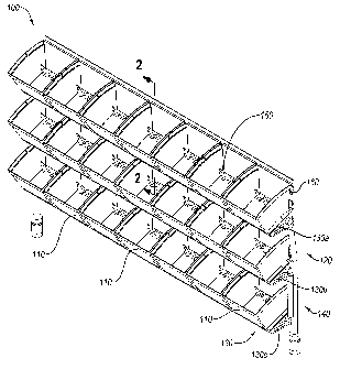
wall module of a modular wall system. For example, Figure 4 illustrates a
CA 02780360 2012-06-20
19
reconfigurable modular wall system 360 comprising a plurality of wall modules
362b,
362c. The wall modules 362b, 362c can include one or more live plant systems
100.
Accordingly, one wall modules incorporating live plants 362b, 362c can couple
to one
or more other wall modules, thereby forming a reconfigurable modular wall
system.
The reconfigurable modular wall system can incorporate any number of wall
modules
incorporating live plant systems or wall modules including no live plant
systems.
The installer can couple and decouple the wall modules and/or the wall
module incorporating live plant systems using connectors. Accordingly, the
installer
can move and rearrange, thereby forming reconfigurable modular wall system
incorporating one or more live plant systems 100 that can have any shapes,
size,
and/or configuration desired by the installer. After rearranging the wall
modules
and/or wall modules362b, 362c incorporating live plant systems 100 into a new
configuration, the installer, for instance, can reconnect the water supply
system 350
and drainage system 360 to the plumbing and sewer systems of the building,
respectively. In one or more implementations, the installer can use flexible
connectors (e.g., hoses) to make such connections.
Furthermore, the installer can use one or more reconfigurable modular wall
systems incorporating one or more live plant systems 100 to form individual
spaces of
various shapes, sizes, and configurations. In particular, the installer can
arrange the
reconfigurable modular wall system incorporating one or more live plant
systems 100
to form one or more individual spaces (e.g., offices, hallways, cubicles,
rooms, etc.)
of desired shapes and sizes. In at least one implementation, the
reconfigurable
modular wall system incorporating one or more live plant systems 100 can
incorporate live plants on both sides thereof. Alternatively, the
reconfigurable
modular wall system 360 incorporating one or more live plant systems 100 can
have
live plants on a single side.
As illustrated in Figure 4, a design or user can mount of various sizes and
configurations of indoor live plant systems 100 to the wall modules 362b,
362c.
Furthermore, in at least one implementation, the installer can conceal at
least a portion
of the watering system 120 within the wall module 362b, 362c. For example, the
connection pipes 140, water supply system 350, and/or drainage system 360 can
couple to the panel 160a on an inner portion of the panel 160a. In other
words, the
CA 02780360 2012-06-20
connection pipes 140, water supply system 350, and drainage system 360 can be
concealed within the wall module 362b. Such concealment can further increase
the
aesthetic of the indoor live plant system 100 as well as of the wall module
incorporating live plants.
5 As shown by Figure 4, the live plant systems 100 can comprise an array of
planters 110 (e.g., 12 planters 110). Alternatively, the live plant systems
100 can
comprise a single row or single planter 110. Thus, one will appreciate that
the system
of the present invention can allow a designer/builder to incorporate any
number, size,
or arrangement of planters 110 to provide a desired aesthetic.
10 Figure 5 illustrates a cross-sectional view of the wall module 362b of
Figure 4.
As shown by Figure 5, the wall module 362b can comprise a frame formed by one
or
more upright supports 380 (Figure 4) and one or more cross-members 390. The
cross-members 390 can couple to an upright support 380 on each side of the
wall
module 362b. The upright supports 380 in turn can couple to upright supports
of
15 adjacent wall modules (362c) to form a wall etc. The frame of the wall
module 362b
can provide the support and structure for attaching one or more panels 160a,
392.
As shown by Figure 5, in one or more implementations the panel 160a can
couple directly to the cross-members 390 of the wall module 362b. In
particular, each
cross-member 390 can include an engagement protrusion 394. In one or more
20 implementations, the engagement protrusion 394 comprises an arm with a head
attached to the end. For example, Figure 5 illustrates an arrow-shaped head.
The
panel 160a can in turn include clips 396 including flexible arms that clip or
snap
about the head of engagement protrusions 394 to secure the panel 160a (and
associated indoor live plant system 100) to the wall module 362b. In
particular, the
flexible arms of the clip 396 can surround at least a portion of the head of
the
engagement protrusion 394.
The ability to clip the panel 160a to a frame of a wall module 362b can allow
a
user to selectively remove, move, or reconfigure the position of an indoor
live plant
system 100 within a given modular wall system. For example, referring again to
Figure 4, a user could decide to switch panels 160a and 392b of wall module
362b to
reposition the indoor live plant system 100 from the top of wall module 362b
to the
bottom. Similarly, a user could move panel 160a and the associated indoor live
plant
CA 02780360 2012-06-20
21
system 100 to wall module 362c. One will thus appreciate that the ability of
the panel
160a to selectively couple to the frame of a wall module can provide a
designer with
the ability to move or reconfigure a design space without having to dissemble
the
indoor live plant system 100.
In alternative implementations, the panel of the indoor live plant system 100
may not include clips 396. In such implementations, a user can fasten the
panel 160
(Figure 2) directly to a wall module panel 392 (Figure 5) via screws or other
fasteners.
One will appreciate that such implementations can allow a user to retro fit a
given
wall module with an indoor live plant system 100.
The present invention may be embodied in other specific forms without
departing from its spirit or essential characteristics. The described
embodiments are
to be considered in all respects only as illustrative and not restrictive. The
scope of
the invention is, therefore, indicated by the appended claims rather than by
the
foregoing description. All changes that come within the meaning and range of
equivalency of the claims are to be embraced within their scope.