Note: Descriptions are shown in the official language in which they were submitted.
CA 02780420 2012-05-08
WO 2011/076705 PCT/EP2010/070185
Unit and Device for the preparation of cells and/or particles
in a liquid and method for microscopic analysis
The present invention relates to the preparation of adherent
or non-adherent cells and/or particles contained in a liquid.
Preparation units are well known in the pharmaceutical
industry for observing biological cells, which are contained
in a liquid. For example, such preparation units are
available under the name "Shandon EZ Single Cytofunnel" from
the company Thermo Fisher Scientific Inc., 81 Wyman Street,
Waltham, USA. This unit comprises a storage chamber, a filter
card and an optical glass slide.
The corresponding filter card is made from a highly absorbent
material and has a hole in the center. Usually, the filter
card is arranged adjacent to the glass slide, such that the
hole of the filter card defines a deposition area on the
glass slide. Consequently, the deposition area is
circumvented by the highly absorbent material of the filter
card.
Initially, the liquid containing the cells is held in the
storage chamber separated from the glass slide. After placing
the preparation unit into a dedicated centrifuge, for example
in the "Shandon Cytospin 4 Cytocentrifuge", and upon spinning
the preparation unit with a certain speed, the spinning
action tilts the preparation unit, thereby releasing the
liquid containing the cells from the storage chamber via the
hole in the filter card to the deposition area on the glass
slide. Once the liquid containing the cells has reached the
CA 02780420 2012-05-08
WO 2011/076705 PCT/EP2010/070185
- 2 -
deposition area, the liquid is removed by the highly
absorbent material of the filter card, leaving the cells on
the deposition area of the glass slide. The glass plate then
can be separated from the preparation unit and forwarded for
microscopic observation of the cells.
Although the above-described centrifuge can process 12
preparation units simultaneously, a more effective and
efficient preparation unit and/or preparation device is
desirable.
Therefore it is an aim of the present invention to provide a
preparation unit, a preparation device and a method for a
highly effective, reliable and high-quality preparation of
cells and/or particles contained in a liquid.
According to the invention, this task is solved by a
preparation unit, a preparation device and a method according
to the respective independent claim. Further embodiments of
the preparation unit and of the preparation device according
to the invention are specified in the dependent claims.
In particular the invention suggests a unit for the
preparation of cells and/or particles contained in a liquid,
comprising a storage chamber configured to store the liquid
containing the cells and/or particles and to release the
stored liquid containing the cells and/or particles via an
exit opening upon the application of a predetermined external
force, in particular a centrifugal force. A passage is
arranged adjacently to the exit opening of the storage
chamber, with the exit opening of the storage chamber leading
into the passage. The passage has a cross-section which is
CA 02780420 2012-05-08
WO 2011/076705 PCT/EP2010/070185
- 3 -
larger than that of the exit opening. At the transition from
the exit opening to the passage the wall forms an edge. The
unit further comprises an observation member for receiving
the released liquid containing the cells and/or particles,
and an absorbing means arranged adjacent to the observation
member between the passage and the observation member. The
absorbing means has an aperture allowing the liquid
containing the cells and/or particles to travel through the
aperture onto the observation member. The absorbing means
further removes the liquid from the liquid containing the
cells and/or particles on the observation member so as to
leave the cells and/or particles on the observation member
for observation. The preparation unit according to the
invention is a small and simple unit for a cost-effective,
reliable and high-quality preparation of cells, in particular
for non-adherent cells, or for other particles originally
contained in a liquid.
The liquid is stored in the storage chamber in a hanging
state against the gravitational force acting on the liquid
without the need to apply any additional external force. This
is achieved by adhesion forces and/or surface tension, which
can be favorably influenced by a suitable shape of the
storage chamber or its exit opening. Thus, the liquid can be
reliably held in the storage chamber so that an uncontrolled
contact of the liquid with the absorbing means prior to
releasing the liquid from the storage chamber is prevented.
In addition, a careful treatment of the cells and/or
particles is ensured. Damages during the preparation are
reduced or completely avoided resulting in a decreased cell
mortality and/or particle deformation. Further, clogging of
CA 02780420 2012-05-08
WO 2011/076705 PCT/EP2010/070185
- 4 -
the cells is avoided thereby providing highly reproducible
results over a large number of preparations. This is
particularly advantageous if a plurality of preparations
units is provided by a multi-well plate, with processing of
the various liquids containing the cells or particles being
performed in parallel.
In addition, using the preparation unit according to the
invention the cells and particles can sediment in the liquid
held in the storage chamber under uniform conditions. This
sedimentation remains basically undisturbed during the
release of the liquid with the cells and particles.
Therefore, the resulting cell distribution on the deposition
area is very homogeneous. Homogeneous distributions are
advantageous as they provide good observation conditions, in
particular for automatic image analysis.
By way of example, the units according to the invention can
be used for the preparation of cells and/or particles in the
pharmaceutical industry.
The retention of the liquid in the storage chamber with the
aid of adhesion forces and/or surface tension is enhanced by
means of the edge arranged at the exit opening of the storage
chamber. Consequently, the liquid can be reliably held in the
storage chamber in any orientation of the storage chamber
without the application of additional external forces.
A centrifugation process is particularly advantageous for the
attachment of non-adherent cells to the observation chamber,
because the use of adhesive chemicals can be avoided.
Adhesive chemicals bear the risk, that they are potentially
CA 02780420 2012-05-08
WO 2011/076705 PCT/EP2010/070185
- 5 -
altering the induction state of the cells, for instance, by
interaction with extracellular matrix proteins.
In a first embodiment of the unit according to the invention,
the wall of the edge at the transition between the exit
opening and the passage includes an angle of 90 degrees. Such
a transition is easy to manufacture. However, other shapes of
transitions are also possible for example a staggered shape
or an edge including an angle other than 90 degrees.
The angle may be dimensioned to provide a good match between
the properties of the liquid and the properties of the
material of the wall forming the edge. For example, for a
liquid having a high creeping capability the edge may have
the shape of a peak, i.e. it may include an angle of less
than 90 degrees.
In a further embodiment of the preparation unit according to
the invention, the storage chamber comprises a dome-shaped or
funnel-shaped portion and a cylindrically-shaped portion
adjoining the dome-shaped or funnel-shaped portion. In a
further embodiment of the preparation unit according to the
invention, the storage chamber is configured to contain a
predetermined volume of the liquid containing the cells
and/or particles, wherein the predetermined volume is between
1 l and 1000 l, particularly between 10 l and 100 l, and
is especially 50 l. This is an amount which is typically
used in the pharmaceutical industry, where small volumes of
liquid preparations are to be processed.
In a further embodiment of the preparation unit according to
the invention, the storage chamber comprises a vent opening
CA 02780420 2012-05-08
WO 2011/076705 PCT/EP2010/070185
- 6 -
arranged at that end of the storage chamber opposite the exit
opening. This allows for a careful and uniform release of the
stored liquid from the storage chamber during centrifugation.
The space left by the released liquid fills with gas, e.g.
air, through the vent opening. Thus, any adverse effects on
the cells or particles contained in the liquid resulting from
a non-uniform or careless release of the liquid can be
prevented.
Further, for loading the storage chamber the liquid
containing the cells and/or particles can advantageously be
dispensed into the storage chamber through this vent opening.
In particular, this can be achieved by putting the open end
of a pipette containing the liquid with the cells and/or
particles onto the wall surrounding the vent opening, and
then by applying a pressure on the liquid contained in the
pipette so as to make the liquid travel through the vent
opening towards the storage chamber. As the walls of the
storage chamber become wetted by the liquid, the liquid
containing the cells and/or particles is sucked into the
storage chamber. The preparation unit may be pre-assembled,
namely by combining the storage chamber with the absorbing
means and/or the observation member, and the storage chamber
may then be loaded with the liquid with the aid of a
pipetting robot. It should be mentioned, however, that
although loading of the storage chamber through the vent
opening is preferred, loading of the storage chamber from the
opposite end is also possible.
In a further embodiment of the preparation unit according to
the invention the observation member is a slide for optical
observations. In particular, the slide for optical
CA 02780420 2012-05-08
WO 2011/076705 PCT/EP2010/070185
- 7 -
observations is a transparent slide, e.g. a glass slide such
as a microscopic slide, and may be coated or uncoated.
In a further embodiment of the preparation unit according to
the invention, the absorbing means comprises a filter paper.
Filter paper provides a high absorbing capacity and is
comparatively cheap. Of course, absorbing means other than
filter paper can be used as well.
In a further embodiment of the preparation unit according to
the invention, the portion of the absorbing means surrounding
the aperture has a predetermined thickness so as to achieve a
predetermined absorbing speed for the liquid. The absorbing
speed is a parameter that is to be controlled so as to allow
the cells and/or particles to settle on the observation
member rather than being dragged away with the liquid that
moves towards and into the absorbing means.
The absorbing means may have a step-shape so that it
comprises an inner region directly adjacent to the aperture,
where the absorbing means is compressed so as to control the
absorbing speed, and an outer region around that inner region
where the absorbing means is uncompressed and has high
absorbing capacity. This enables both, a controlled absorbing
speed as well as the removal of a large amount of liquid and
further prevents cross-contamination in case of adjacently
arranged units.
Preferably, the surface of the absorbing means adjacent to
the aperture is flat, plane, even or smooth and without any
fibers leaking into the aperture or the area on the
observation member where the cells are deposited. This
CA 02780420 2012-05-08
WO 2011/076705 PCT/EP2010/070185
- 8 -
provides for a high reproducibility of the preparation
process.
The passage into which the exit opening of the storage
chamber leads may be shaped to form a further edge, which
upon assembly of the unit presses the absorbing means against
the observation member to prevent gaps between the absorbing
means and the observation member. This prevents cells and/or
particles to escape from the deposit area on the observation
member and also prevents cross-contamination between
adjacently arranged units.
In a further embodiment of the preparation unit according to
the invention, the wall portion of the absorbing means
surrounding the aperture is pre-bent towards the observation
member, so that upon assembly of the unit this portion is
tightly attached to the observation member. With this
configuration, gaps between the observation member and the
absorbing means are avoided.
The invention further suggests a preparation device
comprising a plurality of individual preparation units as
described above, wherein the individual units are mutually
isolated against cross-contamination. With this device
multiple preparations can be performed in parallel, thus
enabling an automated high-throughput preparation,
observation and/or analysis of the cells and/or particles.
One embodiment of the preparation device according to the
invention comprises a 96 well-plate or a 384 well-plate,
wherein the storage chambers of the plurality of the
individual units are formed by the wells of the 96 well-plate
CA 02780420 2012-05-08
WO 2011/076705 PCT/EP2010/070185
- 9 -
or the 384 well-plate, respectively. This has the advantage
that the storage chambers of the individual units are
combined in a compact standard well-plate having standardized
distances between the wells and having standardized foot-
prints so that they can be handled very efficiently by
standard equipment for such multi-well plates. For example,
it is possible to simultaneously load all storage chambers of
the individual wells of such a plate.
In a further embodiment the preparation device according to
the invention comprises an observation plate forming the
observation members of the individual units. Thus, the
observation members of the individual units can be handled
jointly to provide an efficient observation through automated
image analysis.
In a further embodiment the preparation device according to
the invention comprises first and second absorbing sheets
forming the absorbing means of the individual units, with the
first absorbing sheet being arranged directly adjacent to and
in contact with the observation plate, and with the second
absorbing sheet being arranged adjacent to and in contact
with the first absorbing sheet on the side remote from the
observation plate. The second absorbing sheet has an
absorption capacity adding to that of the first absorbing
sheet (for example, the absorption capacity of the second
absorbing sheet can be higher than that of the first
absorbing sheet). This has the advantage that the total
amount of liquid to be absorbed can be increased and that the
mutual isolation of the individual preparation cells is
improved, thus reducing the risk of cross-contamination.
CA 02780420 2012-05-08
WO 2011/076705 PCT/EP2010/070185
- 10 -
In a further embodiment the preparation device according to
the invention comprises a spring plate for applying
individual compression forces to the individual units so as
to achieve a tight attachment of the respective absorbing
means to the respective observation member. The compression
force firmly presses the absorbing means against the
observation member to prevent gaps (see above). Also, the
compression compensates for individual variations of the
thickness of the first absorbing sheet.
In a further embodiment of the preparation device according
to the invention the spring plate comprises a plurality of
spiral-shaped springs corresponding to the number of the
individual units. Each spiral-shaped spring acts on an
individual unit. This results in an individual pressure force
being applied to each individual preparation unit, pressing
the individual part of the observation plate towards the
individual storage chamber with the respective absorbing
means being arranged therebetween. The spiral-shaped springs
may be cone-shaped, for example.
The invention further involves a method for the preparation
of cells (in particular but not exclusively of non-adherent
cells) contained in a liquid, comprising the steps of:
dispensing a liquid containing the cells into a storage
chamber; holding the liquid containing the cells in the
storage chamber against its gravitational force only by means
of adhesion force and/or surface tension; applying an
additional predetermined external force, in particular a
centrifugal force, to the liquid containing the cells in
order to release the liquid from the storage chamber onto an
observation member; removing the liquid from the observation
CA 02780420 2012-05-08
WO 2011/076705 PCT/EP2010/070185
- 11 -
member, leaving the cells on the observation member for
observation.
Through the application of the additional predetermined
external force, in particular the centrifugal force, the
cells are attached to the surface of the observation member.
In addition, the cells are flattened through the application
of the said force so that structures within the cell much
more often come to lie laterally adjacent to each other than
on top of each other. This improves the microscopic analysis
of the cell structures since a microscopic image essentially
is a two-dimensional projection of the three-dimensional
cell-structures. This may be of particular relevance for the
determination of genotoxic effects a substance to which the
cells have been exposed may have on structures or components
of the cells, such as on endosomes, mitochondria, nuclei or
micro-nuclei.
While after deposition of the cells on the observation member
the cells can be dryed and then subjected to microscopic
analysis, one embodiment of the preparation method according
to the invention further comprises the step of applying onto
the observation member having the cells deposited thereon a
coating comprising a hydrogel. The hydrogel contains at least
one stain which is capable of binding to a dedicated
component of the cells. The stain bound to the dedicated
component of the cells is fluorescent upon being excited with
light of a predetermined wavelength, while it is not
fluorescent as long as it is not bound to such dedicated cell
component.
By way of example, the hydrogel may be an agarose hydrogel
CA 02780420 2012-05-08
WO 2011/076705 PCT/EP2010/070185
- 12 -
that keeps the cells deposited on the observation member in a
wet state. A hydrogel can be advantageous with respect to
maintaining the morphology of the cells deposited on the
observation member (e.g. a microscope slide) or on the afore-
mentioned observation plate. A hydrogel such as the afore-
mentioned agarose hydrogel - at room temperature - is in a
state similar to gelatine, that is to say it is essentially
solid. It protects the cells from drying out as well as from
getting polluted. However, small molecules like the molecules
of the stain, are substantially freely movable in the
hydrogel and diffuse through the hydrogel and into the cells
where they bind to dedicated cell components, such as for
example nuclei, micro-nuclei, other dedicated components of
the cell, or to the cell boundary.
This embodiment is advantageous since in contrast to applying
the stain to the cells deposited on the observation member,
washing away from the observation member any excess stain
that has not diffused into the cells prior to placing the
observation member with the stained cells under a microscope
for microscopic analysis, the step of washing away can be
completely omitted, since the stain is already contained in
the hydrogel and diffuses into the cells without the need to
wash away any excess stain.
Therefore, another aspect of the present invention is related
to a method for microscopic analysis of cells, comprising the
steps of
- preparing the cells using the afore-mentioned preparation
method according to the invention,
- illuminating the cells with light of a predetermined
wavelength
CA 02780420 2012-05-08
WO 2011/076705 PCT/EP2010/070185
- 13 -
- placing the prepared cells under a microscope and
- analyzing the microscopic image.
Only the stains that have diffused into the cell and that
have bound to the dedicated components of the cell exhibit
fluorescence after having been illuminated with light of a
predetermined wavelength. For example, the stain may be
adapted to bind to nuclei and to potential micro-nuclei of
the cells. Thus, the formation of micro-nuclei can be
determined which may be an indication that a particular
substance to which the cells have been exposed prior to
microscopic analysis may be genotoxic.
In case an additional stain has been provided and diffused
into the cells and has bound to the cell boundaries, and
after the cells have been illuminated with light of a further
predetermined wavelength the additional stain also exhibits
fluorescence so that both the boundaries of the cells as well
as any dedicated structures within the cells are clearly
visible, thus further enhancing the contrast of the
microscopic image.
The invention is described in more detail hereinafter by way
of exemplary embodiments and with reference to the attached
drawings. It is shown in:
Fig. 1 a cross-sectional view of an embodiment of an
individual preparation unit according to the
invention;
Fig. 2 an exploded perspective view of an embodiment of a
preparation device according to the invention;
CA 02780420 2012-05-08
WO 2011/076705 PCT/EP2010/070185
- 14 -
Fig. 3 a side view of the preparation device of Fig. 2;
Fig. 4 a cross-sectional view along line IV-IV of Fig. 3;
Fig. 5 an enlarged view of detail V of Fig. 4;
Fig. 6 an enlarged view of detail VI of Fig. 4;
Fig. 7 an enlarged view of detail VII of Fig. 2;
Fig. 8 a side view of the preparation device of Fig. 2 in
the assembled state;
Fig. 9 a cross-sectional view along line IX-IX of Fig. 8;
Fig. 10 an enlarged view of detail X of Fig. 9;
Fig. 11 a perspective view of the preparation device of
Fig. 2 in the assembled state,
Fig. 12 a detail of an observation plate of the device of
Fig. 2 with cells deposited thereon, covered with a
hydrogel containing stains,
Fig. 13 example images of non-adherent cells prepared in
with the device and method according to the
invention, and
Fig. 14 examples of analysis results of a micronucleus test
performed using the device and method according to
the invention.
CA 02780420 2012-05-08
WO 2011/076705 PCT/EP2010/070185
- 15 -
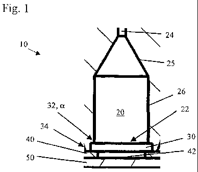
Fig. 1 shows a cross-sectional view on an embodiment of an
individual preparation unit 10 for the preparation of cells
and/or particles contained in a liquid according to the
invention.
The preparation unit 10 comprises a storage chamber 20 for
storing a cell suspension. Storage chamber 20 comprises a
dome-shaped or funnel-shaped portion 25 and a cylindrically-
shaped portion 26 adjoining the dome-shaped portion 25.
Storage chamber 20 may be configured to contain a
predetermined volume of the cell suspension, which is
generally between 1 l and 1000 l, in particular between
10 l and 100 l, and is especially 50 l. At the end remote
from the dome-shaped portion 25 the storage chamber 20
comprises an exit opening 22. Storage chamber 20 further
comprises a vent opening 24 that leads into the dome-shaped
portion 25.
A cylindrically-shaped passage 30 is arranged adjacently to
the exit opening 22 of storage chamber 20. The passage 30 has
a cross-section which is larger than the cross-section of the
exit opening 22. In particular, the passage 30 is coaxially
aligned with the exit opening 22 of the storage chamber 20.
At the transition from the exit opening 22 to the passage 30
the wall forms an edge 32. In this embodiment, the edge 32
includes an angle a of 90 degrees.
An absorbing means 40 embodied as filter paper 40 is arranged
adjacently to the passage 30, on the side remote to the exit
opening 22 of the storage chamber 20. The filter paper 40 can
be a plotting paper or a chromatography paper, in particular
a Grade 17 Chr paper available from the company Whatman Ltd,
CA 02780420 2012-05-08
WO 2011/076705 PCT/EP2010/070185
- 16 -
Brentford, London, United Kingdom. The filter paper 40 has an
aperture 42. The aperture 42 is coaxially aligned with
cylindrically-shaped passage 30.
An observation member 50 embodied as a glass slide 50 is
arranged adjacently to the filter paper 40 such that the
filter paper 40 is arranged between the passage 30 and the
glass slide 50. Further, the passage of the preparation units
is shaped to form a further edge 34, which is arranged
10 adjacently to the filter paper 40. Edge 34 presses the filter
paper 40 towards the glass slide 50 to prevent gaps between
the filter paper 40 and the glass slide 50.
Portions 25 and 26 form an inner hollow space of the storage
chamber 20 for storing the cell suspension that comprises the
liquid and the cells contained in the liquid as long as no
external forces other than the gravitational force are
applied. In this respect, edge 32 in connection with adhesion
forces and/or surface tension helps to retain the cell
suspension in storage chamber 20 against the gravitational
force. Upon the application of a predetermined centrifugal
force, however, the cell suspension is released from storage
chamber through exit opening 22. Air may then flow through
vent opening 24 into storage chamber 20, thus filling the
empty space which is left behind by the released cell
suspension. Vent opening 24 can also be used to fill the cell
suspension into storage chamber 20 by putting the ends of a
pipette on the wall around vent opening 24, applying a
predetermined pressure on the cell suspension in the pipette
(e.g. by squeezing the pipette), so that the cell suspension
is drawn through vent opening 24 into the widening dome-
shaped portion and then into cylindrical portion 26 of
CA 02780420 2012-05-08
WO 2011/076705 PCT/EP2010/070185
- 17 -
storage chamber 20.
Passage 30 and aperture 42 allow the cell suspension, which
has been released from the storage chamber 20, to travel from
storage chamber 20 to glass slide 50. Glass slide 50 serves
to receive the released cell suspension through aperture 42.
Aperture 42 of filter paper 40 is configured to contact the
received cell suspension so as to remove the liquid from the
cell suspension and to leave the cells deposited on glass
slide 50. The absorbing speed of the liquid can be controlled
by the height of the portion of filter paper 40 surrounding
aperture 42. Once the liquid has been absorbed and the cells
have been deposited on glass slide 50, glass slide 50 can be
transported to an imaging device, e.g. a microscope or a
plate reader.
Fig. 2 shows an exploded perspective view of an embodiment of
the preparation device according to the invention. This
preparation device comprises a stack of different plates and
sheets, namely in the following order from the bottom to the
top: a base plate 700, a spring plate 600, an intermediate
plate 602, an observation plate 500 (e.g. a glass plate), a
first absorbing sheet 400 (e.g. a first filter sheet), a
second absorbing sheet 402 (e.g. a second filter sheet), a
well-plate 200 (e.g. a funnel plate) and a cover plate 702.
The preparation device comprises 96 individual units 10 (see
Fig. 1). Well plate 200 comprises the storage chambers 20 and
the passages 30, the first absorbing sheet 400 comprises the
absorbing means 40, and observation plate 500 comprises the
observation members 50.
CA 02780420 2012-05-08
WO 2011/076705 PCT/EP2010/070185
- 18 -
The intermediate plate 602 serves to compensate different
pressure forces exerted by the individual springs of the
spring-plate 600 on the individual preparation units 10.
Further, the intermediate plate 602 prevents scratching of
the observation plate 500 by the springs 604 of the spring
plate 600 (see also detail VII in Fig. 7).
Base plate 700 comprises a plurality of pegs 706, which help
to bring the stack of plates in proper alignment during
assembly. These pegs 706 engage with corresponding holes in
spring plate 600 and in well-plate 200. Further, a clamp 704
is shown, which is suitable to hold the assembled and
compressed stack together as a compact preparation device. To
this end, the clamp 704 is U-shaped, wherein the two bent
edges are configured to engage into grooves which are present
in the side walls of base plate 700 and cover plate 702.
Fig. 3 shows a side view of the preparation device of Figure
2 and Fig. 4 shows a cross-sectional view along line IV-IV of
Fig. 3, referring to the same reference numbers. Detail V
showing a part of the well plate 200 is shown enlarged in
Fig. 5 and detail VI showing a part of the first absorbing
sheet 400 is shown enlarged in Fig. 6. These parts are
described in more detail below.
Fig. 5 shows an enlarged view of detail V of the well-plate
200 of Fig. 3. Detail V shows a portion of two of the 96
individual preparation units of the well-plate 200. Each
portion of the individual units comprises a storage chamber
20 and the passage 30 for individually storing and releasing
the individual cell suspensions.
CA 02780420 2012-05-08
WO 2011/076705 PCT/EP2010/070185
- 19 -
Fig. 6 shows an enlarged view of detail VI of the first
absorbing sheet 400 of Fig. 3. This detail shows one complete
unit of the 96 individual units of the absorbing sheet 400
comprising aperture 42 surrounded by the absorbing sheet 400.
Absorbing sheet 400 has a step-shaped cross-section in an
area surrounding the aperture 42 with an inner region 44
surrounding aperture 42 and having a smaller thickness, and
with an outer region 45 surrounding inner region 44 and
having a thickness greater than that of inner region 44. The
smaller thickness of the inner region 44 can be obtained by
compressing absorbing sheet 400. By means of this compression
the absorbing speed of the liquid can be adjusted to a
desired speed. The outer region 45 remains uncompressed to
exhibit a high absorbing capacity for the liquid to be
removed.
Fig. 7 shows an enlarged view of a detail of the spring plate
600 of Fig. 2 with two spiral-shaped springs 604. The spiral-
shaped springs 604 are arranged between the spring plate 600
and the intermediate plate 602. Each spiral-shaped spring 604
acts on an individual unit 10 (see Fig. 1). Therefore, the
force of each spring 604 applies an individual pressure force
on the corresponding area of the intermediate plate 602,
which in turn applies a pressure force on the corresponding
area of observation plate 500, which is pressed towards well-
plate 200 comprising the individual storage chambers 20.
The spiral-shaped springs 604 may be cone-shaped, with a
spring winding having a large diameter being adjacently
arranged to the spring plate 600 and with the diameters of
the windings decreasing in the direction towards the
intermediate plate 602.
CA 02780420 2012-05-08
WO 2011/076705 PCT/EP2010/070185
- 20 -
Fig. 8 shows a side view of the preparation device of Fig. 2
in the assembled state, and Fig. 9 shows a cross-sectional
view along line IX-IX of Fig. 8. The two clamps 704 (only one
being shown) are holding the assembled and compressed stack
of plates and sheets together as a compact preparation
device. This is achieved with the aid of the two bent edges
of each clamp 704, which engage into grooves in the side
walls of the base plate 700 and the cover plate 702. Detail X
of the preparation device is shown in Fig. 10 and further
described in more detail below.
Fig. 10 shows an enlarged view of detail X of the preparation
device of Fig. 9, and in particular this detail shows two
completely assembled preparation units 10. The second
absorbing sheet 402 is arranged adjacent to and in contact
with the first absorbing sheet 400 on the side remote from
observation plate 500. The second absorbing sheet 402 has a
absorbing capacity higher than that of the first absorbing
sheet 400. This increases the total amount of liquid which
can be absorbed by the absorbing sheets, and helps to improve
the mutual isolation of the individual preparation cells thus
reducing the risk of cross-contamination.
Fig. 11 shows a perspective view of the preparation device
according to Fig. 2 in an assembled state, the stack
including the base plate 700 and the cover plate 702 clamped
together with two clamps 704 (only one clamp being shown). In
the assembled state the preparation device is very compact
and robust and can easily be placed into a centrifuge. In
this embodiment the preparation device has a standard
footprint. Therefore, it can be placed without any
CA 02780420 2012-05-08
WO 2011/076705 PCT/EP2010/070185
- 21 -
modifications into a conventional centrifuge, e.g. the
"Shandon Cytospin 4 Cytocentrifuge".
The preparation device according to Figures 2 to 11 comprises
a plurality of individual units 10 being mutually isolated
against cross-contamination and is therefore suitable for
multiple preparations being performed in parallel. Well-plate
200 provides the storage chambers 20 and the passages 30 of
the individual units 10 in a compact manner having
standardized distances between the wells and having
standardized foot-prints. Observation plate 500 provides
observation members 50 of the individual units 10 so that the
observation members 50 can be handled jointly to provide an
efficient observation through automated image analysis. First
absorbing sheet 400 serves as primary means for removing the
liquid from the observation plate 500, however, with a
controlled absorbing speed so as to prevent cells from being
dragged away together with the liquid during absorption.
Second absorbing sheet 402 serves to assist first absorbing
sheet 400 in removing the liquid, and for improving the
mutual isolation of the individual preparation units.
Intermediate plate 602 serves for uniformly distributing the
individual compression forces applied by the springs 604 of
spring plate 600 and prevents scratching of the observation
plate 500 by the springs 604. Spring plate 600 serves for
applying a compression force to the stack of plates and
sheets, which is held together in a compact and robust manner
with the aid of base plate 700, cover plate 702, and clamps
704. Pegs 706 serves for proper alignment of the stack of
plates during assembly. In case it is desirable to increase
the compression force, an additional spacer plate may be
CA 02780420 2012-05-08
WO 2011/076705 PCT/EP2010/070185
- 22 -
inserted with the rest of the stack remaining unchanged (thus
increasing the compression of the springs of spring plate
600). The entire assembled preparation device may be placed
into a standard centrifuge, so that a plurality of cell
preparations can be performed simultaneously.
As has been mentioned above, it may be advantageous to apply
a hydrogel containing one or more stains to the cells
deposited on the observation member or on the observation
plate, respectively. The hydrogel may contain at least one
stain, which is capable of binding to a dedicated component
of the cells. For example, the hydrogel is an agarose
hydrogel and contains two stains, one being adapted to bind
to dedicated components or structures of the cell, e.g. to
nuclei or micro-nuclei, and the other stain being adapted to
bind to the cell boundaries. When bound to the dedicated
components or structures, or to the cell boundaries,
respectively, the respective stain is fluorescent upon being
excited with light of a respective predetermined wavelength,
while it is not fluorescent as long as it is not bound to
such dedicated cell component, structure or boundary.
The agarose hydrogel keeps the cells deposited on the
observation member in a wet state which can be advantageous
with respect to maintaining the morphology of the cells
deposited on the observation member or on the observation
plate. A hydrogel such as the afore-mentioned agarose
hydrogel - at room temperature - is in a state similar to
gelatine, that is to say it is essentially solid. It protects
the cells from drying out as well as from getting polluted.
However, small molecules like the molecules of the stain, are
substantially freely movable in the hydrogel and diffuse
CA 02780420 2012-05-08
WO 2011/076705 PCT/EP2010/070185
- 23 -
through the hydrogel and into the cells where they bind to
dedicated cell components, such as for example nuclei, micro-
nuclei, other dedicated components of the cell, or to the
cell boundary.
A detail of an observation plate 500 with cells 501 deposited
thereon and covered with a hydrogel 502 containing the stains
is schematically shown in Fig. 12. The so prepared observa-
tion plate 500 can be stored for a predetermined time so as
to allow the stains to diffuse into the cells 501 and to bind
to the nuclei and potential micro-nuclei and to the cell
boundaries respectively. Subsequently, the cells may be
subjected to microscopic analysis yielding a high contrast
microscopic image of the cells and cells structures.
A more detailed example of the method will be described in
the following:
Cell culture
Mouse lymphoma cells of the type "L5178Ytk+i-" are grown in
suspension in T-175 flasks in RPMI 1640 medium containing 10%
horse inactivated serum, 2 mM L-glutamine, and 1% pen/strep
antibiotics to 75% confluency and 95% viability (all media
available from Life Technologies Corporation, Carlsbad,
Compound incubation
Compound incubation is done in 96 well plates of the type
"Falcon 353077" available from Beckton Dickinson, New Jersey,
USA, for 24 hours at 37 C, 5% C02 with 8000 cells in 60 l
growing medium. Compounds are dissolved in dimethyl sulfoxide
DMSO (occasionally in water), at a final DMSO concentration
CA 02780420 2012-05-08
WO 2011/076705 PCT/EP2010/070185
- 24 -
of 1%. As a positive control, 15 g/ml methylmethanesulfonate
(MMS) was used.
Cell centrifugation & fixation
Of the cell suspension, 50 pl are transferred from the
incubation plate into the chambers of an inverted funnel
plate (see chambers 20 of well plate 200 shown in Fig. 4 and
Fig. 5) using a 96-head of an automated pipetor of the type
"CyBi-well" available from the company CyBio AG, Jena,
Germany, after mixing five times using 250 pl pipette tips.
The cell preparation device is assembled essentially as shown
in Fig. 2. A spring plate 600 comprising of 96 spiral springs
of equal strength is placed on top of the base plate 700 of
the frame and covered with a thin and flexible metal
intermediate plate 602 for protection. Next in the stacked
assembly, a dedicated glass plate 500 is serving as the
observation plate to receive the cells. This plate may be a
"Nexterion" glass plate available from Schott Technical Glass
Solutions GmbH, Jena, Germany. Two perforated filter paper
plates 400 and 402 are used, each having 96 holes at SBS-
standard spacing (SBS = Society for Biomolecular Science).
The first filter plate 400, which is in contact with the
glass plate 500, is to form the boundaries of each of the 96
sample spots and to remove the medium from the suspension
during centrifugation (3.5 mm diameter holes). In order to
achieve a homogeneous and isotropic liquid removal with a
defined speed, the filter material was pressed in the shape
of a ring around each well to a thickness of 0.5 mm.
The second filter plate 402, which is lying on top of the
first filter plate 400 in loose contact, is to increase the
retention capacity of the first filter plate 400 and
CA 02780420 2012-05-08
WO 2011/076705 PCT/EP2010/070185
- 25 -
comprises larger holes (7.0 mm diameter) for a better fit
around the edges 32 of the inverted funnel plate 200.
The funnel plate 200 filled with cell suspension is carefully
placed on top of the first filter plate 400 and fitting into
the holes of the second filter plate 402. The assembly is
finished by the cover plate of the preparation device.
Precompressed by a manual lever press, the preparation device
is fixed using two metal brackets 704 from the side that take
virtually no space, such that the whole device fits into the
micro-titer plate bucket of a commercial centrifuge, e.g. of
the type "Multifuge 1S" available from the company Heraeus,
Germany. This particular centrifuge accelerates immediately
to the set centrifugation speed of 1000RPM, which is
maintained for 5 minutes. After disassembly of the
preparation device, the plates are drying in ambient air for
1 min, then immersed in 70% ethanol/water over night for
fixation and up to a week for storage.
Staining and mounting
After fixation, the glass plates were dried for 1 minute with
the excess liquid shaken off and immersed in phosphate
buffered saline (PBS) for 5 minutes as a preconditioning. The
bottom side of the plates opposite to the surface were the
cells have been deposited on was quickly rinsed with double
distilled water (ddH2O) and, then the plates were ready for
mounting.
In order to keep the cells in a wet state and to prevent
undesired change of cell morphology and staining artifacts,
it proved to be advantageous to cover the cells with agarose
hydrogel. To this end, "low-melting point low gelling
temperature agarose type VII" available from Sigma-Aldrich
Corporation, Missouri, USA, was dissolved to a final 2%
CA 02780420 2012-05-08
WO 2011/076705 PCT/EP2010/070185
- 26 -
weight/volume solution in PBS in a micro wave oven at 850 W.
It takes several minutes and several boiling and mixing
cycles before the powder is completely dissolved.
Staining of the nuclei of the cells with the stain of the
type "Hoechst" (1 M (H20)) available from Sigma Aldrich
Corporation, Missouri, USA, and of the cytoplasm of the cells
with the stain of the type "cell mask red" (1 }gig/ml (PBS))
available from Life Technologies Corporation, Ca_rls:ad,
Callfonia, CJSSA) can be done in the agarose gel without the
need for any additional washing step. This is due to the fact
that the stain Hoechst is practically non-fluorescent in
solution and only fluorescent when bound to DNA and the fact
that image acquisition is done by confocal excitation and
detection, thus reducing out-of-focus background
tremendously. The liquid agarose solution containing the
stains is kept at 50 C and poured over the plates using a
ml disposable pipette. The solution will stay on the plate
and not spill over the edges due to surface tension. After
20-30 min the gel is hardened and the plates can be mounted
20 in dedicated lidded frames for the glass "Nexterion"
available from the same company as is the glass.
Imaging
Spinning-disc confocal fluorescence microscopy of glass
25 plates carrying 96 features has been performed on the high-
throughput automated imaging system "Opera QEHS" available
from the company PerkinElmer Cellular Technologies, Hamburg,
Germany. The nuclear stain (Hoechst), and the cytoplasmic
stain (cell mask red) were excited by solid state lasers at
405 nm and 635 nm, respectively.
The excitation intensity and duration of the illumination
sources was adjusted in each experiment to account for
CA 02780420 2012-05-08
WO 2011/076705 PCT/EP2010/070185
- 27 -
differences in labeling efficiencies, to optimize brightness
and contrast, and to minimize bleaching (typically, 50 mW
laser output, 200-2000 ms integration time).
At each spot, typically 25 pairs of scanning images were
recorded through a LCPLF 20x NA 0.4 air objective lens
(available from the company Olympus, Japan) and optimized
filter sets by 2 independent high quantum-efficiency 12 bit
CCD cameras (1.3 mega pixels monochrome). Any residual
illumination heterogeneity, image shift or distortion was
corrected for by using separately acquired images from
calibration samples.
Image analysis
Confocal micrographs were analyzed using the proprietary
software environment "Acapella 2.0" of PerkinElmer's "Opera"
imaging system, both available from PerkinElmer Cellular
Technologies, Hamburg, Germany. First, the location of each
cell was identified by segmentation of the nuclear stain
image. Once the nuclei have been localized and their outline
and area has been measured, the outline of the cell was
determined by segmentation of the cytoplasmic stain.
In addition, images of micro nuclei-containing samples were
analyzed by means of the image analysis software "eCognition"
available from the company Definiens AG, Munich, Germany.
Fig. 13 shows example images of non-adherent cells prepared
with the described device and method. In the images of the
upper row the cells have been stained with the stain
"Hoechst" mentioned above, while in the lower row the cells
have been stained with the stain "cell mask red" also
mentioned above. In the left column the cells are have not
been treated while in the right column the cells have been
CA 02780420 2012-05-08
WO 2011/076705 PCT/EP2010/070185
- 28 -
treated with a genotoxic compound. As can be seen, the cells
prepared with the described device and method stick well to
the untreated glass surface, are spread out flat so that
intracellular structures are well separated.
Fig. 14 shows examples of analysis results of a micronucleus
test performed using the device and method described. The
experiments have been performed in replicates on four
different days, as indicated the legend above the graphs. The
proportion of micronuclei-containing cells to all cells is
plotted versus the substance concentration, as is indicated
in the graphs. The upper row contains substances that are
known to be non-genotoxic, while the lower row contains
substances that are known to be genotoxic. From the graphs it
can be seen that all three substances have been correctly
classified. Plates #13 and #14 were treated only with DMSO
(dimethyl sulfoxide) without any toxic substance as a
negative control, and this can be particularly seen in the
graphs shown in the lower row. The cells have been diluted to
12 dilutions of the indicated substances. The concentration
range id defined by the maximum concentration (10 M for
Nitroquinoline oxide and Mitomycin C, 100 M for all other
substances), the dilution factor 1.5, and the number of
dilutions. Cells containing no micronucleus and cells
containing one to three micronuclei have been counted using a
custom made image processing algorithm. In the graph, the
data for Nitroquinoline oxide and Mitomycin C have been
shifted to the right by the factor of ten solely for
displaying purposes.