Language selection

Search

Patent 2780691 Summary

Third-party information liability

Some of the information on this Web page has been provided by external sources. The Government of Canada is not responsible for the accuracy, reliability or currency of the information supplied by external sources. Users wishing to rely upon this information should consult directly with the source of the information. Content provided by external sources is not subject to official languages, privacy and accessibility requirements.

Claims and Abstract availability

Any discrepancies in the text and image of the Claims and Abstract are due to differing posting times. Text of the Claims and Abstract are posted:

  • At the time the application is open to public inspection;
  • At the time of issue of the patent (grant).
(12) Patent: (11) CA 2780691
(54) English Title: AQUACULTURE REARING ENCLOSURE AND CIRCULATION INDUCTION SYSTEM
(54) French Title: ENCLOS D'ELEVAGE POUR AQUACULTURE ET SYSTEME D'INDUCTEUR DE CIRCULATION
Status: Granted and Issued
Bibliographic Data
(51) International Patent Classification (IPC):
  • A01K 63/00 (2017.01)
  • A01K 61/00 (2017.01)
(72) Inventors :
  • ROBINSON, STEPHEN (Canada)
(73) Owners :
  • AGRIMARINE HOLDINGS INC.
(71) Applicants :
  • AGRIMARINE HOLDINGS INC. (Canada)
(74) Agent: PAUL D. GORNALLGORNALL, PAUL D.
(74) Associate agent:
(45) Issued: 2021-10-26
(22) Filed Date: 2012-06-26
(41) Open to Public Inspection: 2013-12-26
Examination requested: 2018-06-26
Availability of licence: N/A
Dedicated to the Public: N/A
(25) Language of filing: English

Patent Cooperation Treaty (PCT): No

(30) Application Priority Data: None

Abstracts

English Abstract

A system for efficiently circulating water in a large volume of rearing space for aquatic organisms, comprising an impervious enclosure for containing the water and aquatic organisms and a pump for pumping water from an intake duct through intake ducting to a flow diverter, which then directs a flow of water radially outward within the enclosure to directly induce a circulation of water within the enclosure. The 'center drive' circulation pattern is sufficiently uniform to provide optimum rearing conditions for cultured finfish, while also ensuring that solid wastes are swept toward the central drain, even in a very large tank.


French Abstract

Système permettant de faire circuler efficacement de leau dans un grand volume dun espace dalevinage pour organismes aquatiques, comprenant une enceinte imperméable destinée à contenir leau et des organismes aquatiques et une pompe pour pomper de leau dune conduite dentrée à un déflecteur découlement en empruntant une canalisation dentrée, le déflecteur découlement dirigeant alors un flux deau de façon radiale vers lextérieur à lintérieur de lenceinte pour induire directement une circulation deau à lintérieur de lenceinte. Le motif de circulation à « entraînement central » est suffisamment uniforme pour fournir des conditions optimales pour lalevinage de poissons à nageoires délevage, tout en garantissant que les déchets solides soient balayés vers la voie dévacuation centrale, même dans un réservoir de très grande taille.

Claims

Note: Claims are shown in the official language in which they were submitted.


CLAIMS
We claim:
1. A systcm for efficiently circulating water in a large volume of rearing
space for aquatic
organisms, comprising: a) an impervious enclosure, having a cylindrical wall,
for containing the
water and aquatic organisms; b) a centrally positioned pump within the
impervious enclosure for
forcing water from a vertical intake duct through intake ducting to a flow
diverter; c) a filter skirt
for trapping debris, a standpipe outlet providing an exit from the impervious
enclosure filtered
excess water, and an annular gutter for trapping heavier solid debris not
caught by the filter skirt;
in which the flow diverter directs a flow of water radially outward within the
enclosure to
directly induce a circulation of water within the enclosure from the centrally
positioned pump
along a surface of the water surface toward cylindrical wall areas of the
enclosure, down the
cylindrical wall areas, and inward along a floor of the enclosure to a
centrally located drain, in a
poloidal flow pattern that induces, by momentum coupling, a secondary toroidal
flow within the
enclosure.
2. The system of claim 1, in which water exits the centrally positioned pump
through the flow
diverter that directs a flow of water radially outward and induces a poloidal
flow to circulate
water within the enclosure.
3. The system of claim 1, in which the impervious enclosure is a buoyantly
supported tank for
use in an open body of water, the intake duct is located outside the tank, and
the pump draws
CA 2780691 2019-12-19

influent water from outside the tank via the intake duct for the flow
diverter.
4. The system of claim 3, in which floatation collars for buoyantly supporting
the tank are
secured around a periphery of the tank by brackcts.
5. The system of claim 1, in which the flow diverter is centrally located
within the impervious
enclosure.
6. The system of claim 1, in which the intake duct is vertically oriented.
7. The system of claim 1, in which the pump is a submersible pump inducing
vertical upward
flow within the intake duct.
8. The system of claim 1, in which the pump comprises a motor which is
connected to and rotates
an impeller blade by means of an elongated shaft inserted down the intake
duct.
9. The system of claim 1, in which the pump and the intake duct are located
along the central axis
of the impervious enclosure, which is radially symmetric.
10. The system of claim 1, in which the intake duct, thc pump, an outlet duct
for the flow
diverter, are accessible from a central axial service platform within the
impervious enclosure.
16
CA 2780691 2019-12-19

11. The system of claim 10, further comprising filtration, oxygenation and
control subsystems
accessible from the central axis circulation platform.
12. The system of claim 1, in which the impervious enclosure is a open-topped
tank supported by
floatation collars and containing a central circulation platform for the
intake duct, the flow
diverter, the pump, and having a central mast assembly that is suspended by
flotation billets to
enable floatation of the central circulation platform within the tank and that
is anchored to
maintain a central location for the circulation platform within the tank.
13. The system of claim 12, in which the mast assembly comprises poles
embedded in the
platform, linked by cross-members, and secured together at the top by a ring
which is secured by
stays attached to brackets around the periphery of the wall.
14. Thc system of claim 1, in which the filter skirt comprises a coaxial upper
slot drain and an
annular lower slot drain.
15. The system of claim 1, in which the standpipe outlet duct is a vertical
standpipe outlet duct
that is located coaxially to the intakc duct, and below the flow diverter.
16. The system of claim 1, in which the impervious enclosure comprises a
cylindrical wall, a
circular bottom, and a central portion holding the intake duct.
17
CA 2780691 2019-12-19

17. The system of claim 1, in which the flow diverter is mounted on a floating
circulation
platform.
18. The system of claim 1, in which the flow diverter comprises a plurality of
vanes.
19. The system of claim 18, in which the plurality of vanes is concentric
series of curved vanes.
20. The system of claim 17, in which the flow diverter comprises a concentric
series of curved
vanes that divert a flow of influent liquid pumped up the intake duct and
radially spreads the flow
of influent liquid along a surface of water within the enclosure from the
floating circulation
platform to a wall of the impervious enclosure.
21. The system of claim 1, in which the flow diverter induces the poloidal
flow and a secondary
toroidal flow of water within the impervious enclosure.
22. The system of claim 21, in which a majority of poloidal flow becomes
outlet flow by
following the surface of a filter skirt entering an upper drain then exiting
through a standpipe
outlet.
23. The system of claim 1 , in which the filter skirt is a tensile fabric
structure made of filter
medium.
1 8
CA 2780691 2019-12-19

24. The system of claim 22, in which a heavier portion of solid debris in the
poloidal flow slides
under the bottom of the filter skirt, and is then is sucked upwards to exit
through the standpipe
outlet.
25. The system of claim 23, in which a heaviest portion of solid debris
settles into an annular
gutter for later removal.
26. The system of claim 1, in which a floating central circulation platform
holding the intake duct
and the flow diverter is a structural truss of supporting floatation billets
made of foam-filled
rotational-molded polyethylene.
27. The system of claim 11, in which the central mast assembly is connected by
rope stays to
brackets supporting the floatation collar, providing structural support
against wave and tidal
forces.
28. The system of claim 22, in which a minority of effluent flow volume passes
through an
annular lower drain slot at a base of the filter skirt carrying heavier
settled solid debris via a
gutter flow path to an annular gutter from which it is periodically pumped.
29. The system of claim 1, in which effluent flow with debris that is lighter
than watcr follows a
supernatant flow upward to combine with a main outlet flow from a coaxial
upper drain slot, and
then leaves the enclosure through a co-axial standpipe outlet.
19
CA 2780691 2019-12-19

30. The system of claim 1, in which the impervious enclosure has opaque walls.
31. The system of claim 1, in which influent liquid travels from the flow
diverter indirectly to a
standpipe outlet that is adjacent to the flow diverter by following a free-
surface boundary radially
to the perimeter of the enclosure, where it is diverted down a wall of the
enclosure, radially back
toward a center axis of the enclosure, and then rises to upper drain standpipe
outlet.
32. The system of claim 2, in which the poloidal flow gives rise to a
Secondary toroidal flow of
greater velocity than thc poloidal velocity.
33. The system of claim 2, in which: a) the impervious enclosure is a
buoyantly supported tank
for use in an open body of water, the intake duct is located outside the tank,
and the pump draws
influent water from outside the tank via the intake duct for the flow
diverter, floatation collars for
buoyantly supporting the tank being secured around a periphery of the tank by
brackets, b) the
flow diverter is centrally located within the impervious enclosure, the intake
duct is vertically
oriented, the pump is a submersible pump inducing vertical upward flow within
the intake duct,
comprising a motor which is connected to and rotates an impeller blade by
means of an elongated
shaft inserted down the intake duct, and the pump and the intake duct are
located along the
central axis of the impervious enclosure, which is radially symmetric, c) the
intake duct, the
pump, an outlet duct for the flow diverter, are accessible from a central
axial service platform
within the impervious enclosure.
CA 2780691 2019-12-19

34. The system of claim 33, in which: a) the impervious enclosure is an open-
topped tank
supported by floatation collars and containing a central circulation platform
for the intake duct,
the flow divertcr, the pump, and having a central mast assembly that is
suspended by flotation
billets to enable floatation of the central circulation platform within the
tank and that is anchored
to maintain a central location for the circulation platform within the tank;
b) the mast assembly
comprises poles embedded in the platform, linked by cross-members, and secured
together at the
top by a ring which is secured by stays attached to brackets around the
periphery of the wall; c)
the standpipe outlet is a vertical standpipe outlet duct that is located
coaxially to the intake duct,
and below the flow diverter; d) the tank comprises a cylindrical wall, a
circular bottom, and a
central portion holding the intake duct.
35. The system of claim 34, in which: a) the flow diverter comprises a
concentric series of curved
vanes that divert a flow of influent liquid pumped up the intake duct and
radially spreads the flow
of influent liquid along a surface of water within the enclosure from the
floating circulation
platform to a wall of the impervious enclosure; b) the flow diverter induces a
poloidal flow and a
sccondary toroidal flow of watcr within the impervious enclosure, the poloidal
flow giving rise to
a secondary, toroidal flow of greater velocity than the poloidal velocity; c)
a majority of poloidal
flow becomes outlet flow by following the surface of a filter skirt, entering
an upper drain, then
exiting through a standpipe outlet; d) the filter skirt is a tensile fabric
structure made of filter
medium; e) a heavier portion of solid debris in the poloidal flow slides under
the bottom of the
filter skirt, and is then is sucked upwards to exit through the standpipe
outlet; 0 a heaviest
portion of solid debris settles into an annular gutter for later removal; g) a
minority of effluent
21
CA 2780691 2019-12-19

flow volume passes through an annular lower drain slot at a base of the filter
skirt, carrying
heavier settled solid debris via a gutter flow path to an annular gutter, from
which it is
periodically pumped; h) effluent flow with debris that is lighter than water
follows a supernatant
flow upward to combine with a main outlet flow from a coaxial upper drain
slot, and then leaves
the enclosure through a co-axial standpipe outlet; i) influent liquid travels
from the flow diverter
indirectly to a standpipe outlet that is adjacent to the flow diverter by
following a free-surface
boundary radially to the perimeter of the enclosure, where it is diverted down
a wall of the
enclosure, radially back toward a center axis of the enclosure, and then rises
to upper drain
standpipe outlet.
36. The system of claim 35, in which a) the floating central circulation
platform holding the
intake duct and the flow diverter is a structural truss of supporting
floatation billets made of
foam-filled rotational-molded polyethylene; b) the central mast assembly is
connected by rope
stays to brackets supporting the floatation collar to provide structural
support against wave and
tidal forces.
22
CA 2780691 2019-12-19

Description

Note: Descriptions are shown in the official language in which they were submitted.


CA 02780691 2012-06-26
AQUACULTURE REARING ENCLOSURE AND CIRCULATION INDUCTION SYSTEM
SPECIFICATION
FIELD OF INVENTION
This invention relates to the rearing of aquatic organisms in a controlled
environment and more
particularly to impervious closed-container rearing systems enclosing and
efficiently circulating
water in a large volume of rearing space.
BACKGROUND OF THE INVENTION
Methods and equipment for induction of circulating flow in aquaculture
enclosures are known in
the art. Circular tanks are most commonly used, due to their inherent
structural strength, and
because they can maintain a characteristic rotating flow, against which
finfish are induced to
swim. Swimming exercise is believed to promote weight gain and feed conversion
efficiency in
some species of finfish.
In one common design, water is introduced into a circular rearing tank at the
perimeter, in a
tangential direction, so as to impart angular momentum to the fluid flow, and
is withdrawn from
the central axis of the tank through a standpipe or floor drain. The primary
flow in this design
1

CA 02780691 2012-06-26
follows a spiral path from the perimeter toward the center. It is also known
that such azimuthal
flow in circular tanks induces a secondary, toroidal flow by a mechanism known
as the 'teacup
effect'; centrifugal pressure exerted on fluid at the rotating free surface
boundary is not balanced
by the slower boundary layer-influenced flow adjacent to the floor of the
tank. The pressure
imbalance induces flow radially outward along the free surface, down the
vertical tank wall, and
radially inward across the floor, back to the central axis, where fluid is
displaced vertically
upward creating a hydraulic circuit. The teacup effect is responsible for the
self-cleaning
property of circular tanks, whereby settle-able solid debris, including fecal
matter, uneaten feed
pellets, and moribund fish, are swept in a spiral path toward the center of
the floor and out
through a drain.
In a variant of this design, the majority of the flow exiting the tank is
drawn from an overflow
weir at the upper side wall, while the solids exit through the center drain
with the remainder of
the flow. This configuration concentrates the solid waste in a relatively
small proportion of the
flow stream and facilitates de-watering and treatment steps of recirculating
aquaculture systems.
US patents 3,653358 and 3,698,359 to Fremont describe a watertight liner
suspended from a
floatation collar of flexibly linked, foam-filled floats and provided with
inlet and outlet pipes,
and oxygen spargers to continuously oxygenate the enclosed water. Flow pattern
is from one
end of an elongate enclosure to the other, as is the case with land-based
'raceway' enclosures, or
is not specified.
2

CA 02780691 2012-06-26
US patent 4,211,183 to Hoult describes a land-based recirculating aquaculture
system with
centrally located upwelling pump and central drain with integral bio-filter.
In one
implementation the bio-filter support follows a spiral path, but no mention is
made of the
circulation pattern within the rearing volume of the tank, or particularly of
the effect of feeding
circulation from the central top surface of the water volume.
US patent 4,798,168 to Vadseth describes a floating closed-containment
aquaculture enclosure
with an externally mounted vertical pump duct drawing water from depth,
discharging
horizontally tangentially into the perimeter of the floating enclosure. Water
follows a spiral path
with induced poloidal component, and exits through a center standpipe drain.
US patent 6,443,100 to Brenton further describes the flow pattern within
floating closed-
containment enclosures, and claims a design of standpipe drain for such
rearing enclosures that
extracts clear effluent and solids through separate pipes.
None of the previously described methods specifically address the changes in
intrinsic fluid
behavior as aquaculture enclosures are scaled from volumes in the order of 100
cubic meters
typical of land-based culture systems to volumes in the order of 10,000 cubic
meters required for
large scale grow-out operations typical in the modern culture of salmonids and
tunas. Such
tanks may have diameters of up to 40 meters, and depths to 15 meters. At this
scale, two
practical difficulties arise with the azimuthal flow pattern and with the
teacup effect. Firstly,
tangential velocity at the perimeter of the tank produced by the flow volume
necessary to
exchange the large volume of enclosed water volume in the time required (on
the order of one
3

CA 02780691 2012-06-26
hour) is higher than the preferred swimming speed of the cultured fish,
particularly in the early
life stages. Secondly, the teacup effect becomes less significant as the
Reynolds number of the
flow increases. At large scale, turbulence and momentum predominate, while
viscosity, which is
responsible for the boundary layer which drives the toroidal flow component,
is less influential
in determining the overall behavior of the flow. In practice, solids are seen
to build up on the
floor of the tank, the central vortex drifts from the axis or bifurcates, and
in extreme cases
multiple concentric toroidal vortices develop, with upwelling zones re-
suspending solids.
BRIEF SUMMARY OF THE INVENTION
It is an object of the current invention to address the shortcomings of
previous methods of
inducing circulation when employed in larger floating seaborne tank
enclosures, particularly
designs in which influent water is introduced in a tangential direction at the
perimeter of the
tank. It is a further object of the current invention to provide a robust
design of pump and
ducting system and a buoyantly supported tank which floats within an enclosing
water body such
as ocean, lake, or reservoir, and which can withstand large environmental
loads from waves,
wind, tide, and ice. It is a further object of the current invention to
provide a platform from
which service access to said pump and ducting system is facilitated.
In a basic form the invention would have a vertically oriented intake duct and
submersible pump
inducing vertical upward flow within the duct, located at the central axis of
a radially symmetric
tank, drawing influent water from some distance below the tank. A flow
diverter fitted to the top
4

CA 02780691 2012-06-26
end of the intake duct directs flow radially outward over the liquid surface
enclosed by the tank
so as to directly induce a poloidal flow pattern within the tank. The overall
flow within the tank
resembles the laminar boundary layer-induced 'teacup effect' flow observed in
smaller tanks, but
with a greater poloidal component, and at a much larger scale.
Because the intake duct, pump, outlet duct, filtration methods, associated
floatation, oxygenation
and control systems may all be located at a common, central axial platform,
advantages are found
in construction cost, maintenance access and structural strength. The 'center
drive' circulation
pattern is sufficiently uniform to provide optimum rearing conditions for
cultured finfish, while
also ensuring that solid wastes are swept toward the central drain, even in a
very large tank.
The invention is essentially a system for efficiently circulating water in a
large volume of rearing
space for aquatic organisms, comprising an impervious enclosure for containing
the water and
aquatic organisms and a pump for pumping water from an intake duct through
intake ducting to a
flow diverter, which then directs a flow of water radially outward within the
enclosure to directly
induce a circulation of water within the enclosure. By "radially outward" is
meant from a center
region of the tank toward peripheral regions of the tank, whether
substantially along radius lines
from a center axis of the tank directly to peripheral points at the tank outer
walls, or more
indirectly on flow lines that are at acute or obtuse angles to tangents on the
periphery of the tank.
The directing of the water thus outward results in qualitative advantages that
are not provided by
the circulation mechanisms of the prior technology.

CA 02780691 2012-06-26
In a preferred embodiment, the flow diverter directs a flow of water radially
outward and
induces a poloidal flow to circulate water within a buoyantly supported tank
for use in an open
body of water. The intake duct is located outside the tank, and the pump draws
influent water
from outside the tank via the intake duct for the flow diverter, floatation
collars for buoyantly
supporting the tank being secured around a periphery of the tank by brackets.
The flow diverter
is centrally located within the impervious enclosure, the intake duct is
vertically oriented, the
pump is a submersible pump inducing vertical upward flow within the intake
duct, comprising a
motor which is connected to and rotates an impeller blade by means of an
elongated shaft
inserted down the intake duct, and the pump and the intake duct are located
along the central
axis of the impervious enclosure, which is radially symmetric. The intake
duct, the pump, and an
outlet duct for the flow diverter, are all accessible from a central axial
service platform within
the impervious enclosure. The impervious enclosure can be an open-topped tank
supported by
floatation collars and containing a central circulation platform for the
intake duct, the flow
diverter, the pump, and having a central mast assembly that is suspended by
flotation billets to
enable floatation of the central circulation platform within the tank and that
is anchored to
maintain a central location for the circulation platform within the tank. The
mast assembly
comprises poles embedded in the platform, linked by cross-members, and secured
together at the
top by a ring which is secured by stays attached to brackets around the
periphery of the wall.
The tank can have a filter skirt for trapping debris, a standpipe outlet
providing an exit from the
impervious enclosure filtered excess water, and an annular gutter for trapping
heavier solid
debris not caught by the filter skirt, the filter skirt comprising a coaxial
upper slot drain and an
6

CA 02780691 2012-06-26
annular lower slot drain. A vertical standpipe outlet duct is located
coaxially to the intake duct,
and below the flow diverter.
In its overall structure, the tank comprises a cylindrical wall, a circular
bottom, and a central
portion holding the intake duct. The floating central circulation platform
holding the intake duct
and the flow diverter is a structural truss of supporting floatation billets
made of foam-filled
rotational-molded polyethylene. The central mast assembly is connected by rope
stays to
brackets supporting the floatation collar, to provide structural support
against wave and tidal
forces.
In an optimal embodiment, the flow diverter comprises a concentric series of
curved vanes that
divert a flow of influent liquid pumped up the intake duct and radially
spreads the flow of
influent liquid along a surface of water within the enclosure from the
floating circulation
platform to a wall of the impervious enclosure. The flow diverter induces a
poloidal flow and a
secondary toroidal flow of water within the impervious enclosure.
BRIEF DESCRIPTION OF THE DRAWINGS
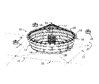
Figure 1 shows a top isometric overview of an Aquaculture Rearing Enclosure
(Tank) moored to
Support Buoys (Platform without Flow Diverter)
Figure 2 shows a side isometric cutaway view of an Aquaculture Rearing
Enclosure (Tank).
7

CA 02780691 2012-06-26
Figure 3 shows a side isometric close-up cutaway view of the Floating
Circulation Platform
(Platform), Filter Skirt and associated elements.
Figure 4 shows a top isometric view of a Floating Circulation Platform with
its Flow Diverter.
Figure 5 shows a top isometric prior art Hatchery Tank with its tangential
outlet and downward
spiral flow pattern.
Figure 6 shows a side isometric cutaway view of the Tank, with induced
poloidal flow and
secondary toroidal flow directions indicated.
Figure 7 shows a top isometric cutaway view of the Tank exposing elements of a
flow diverter.
Figure 8a shows a side cutaway reference view of the Tank, while Figure 8b
shows a close-up of
the flow patterns around the Filter Skirt.
DETAILED DESCRIPTION
All elements will now be introduced by reference to drawing figures, then how
each element
functions and interacts with each other element will be described where
necessary.
8

CA 02780691 2012-06-26
Figure 1 shows an overview of an Aquaculture Rearing Enclosure (Tank) 10
secured by mooring
lines 22 to support buoys 26 by their underwater spars 24. The tank 10 is
comprised of a
cylindrical wall 12 and circular bottom 14 with an intake duct 30 at its
center. Floatation collars
16 are secured around the tank 10 periphery by brackets 18. Safety hand rails
20 are anchored to
the top of the wall 12 between brackets 18; the latter serve as anchors for
one end of each rope
stay 50 which then attaches to the ring 52 at the top of the mast assembly 44.
Note that the
Floating Circulation Platform 28 is without its Flow Diverter 32 in order to
show the how the
mast assembly 44 is anchored within.
Figure 2 shows an internal cutaway view of the Aquaculture Rearing Enclosure
(Tank) 10. The
Floating Circulation Platform (Platform) 28 is comprised of numerous flotation
billets 36 which
provide buoyancy to support the mast assembly 44, pump assembly 54, filter
skirt 38, and intake
duct 30. The mast assembly 44 is comprised of poles 46 embedded in the
platform 28, linked by
cross-members 48, and secured together at the top by a ring 52 which is
secured by stays 50
attached to brackets 18 around the periphery of the wall 12. The pump assembly
54 is comprised
of a motor 56 which is connected to and rotates an impeller blade 60 by means
of an elongated
shaft 58 inserted down the intake duct 30. Also shown is the standpipe outlet
42 which is the
main exit for filtered excess water and an annular gutter 34 which traps
heavier solid debris 66
not caught by the filter skirt 38.
Figure 3 shows a close-up cutaway view of the Floating Circulation Platform
28, with focus on
the location of the coaxial upper slot drain 40 and the annular lower slot
drain 41, both elements
9

CA 02780691 2012-06-26
of the filter skirt 38. (see Figs. 8a & 8b for drainage details) A vertical
'standpipe' outlet 42 duct
is located coaxially to the intake duct 30, and below the flow diverter 32 as
shown.
Figure 4 shows a close-up view of a Floating Circulation Platform 28 with its
Flow Diverter 32
in place, which is comprised of a concentric series of curved vanes 82 which
divert the flow of
influent liquid 62 pumped up the intake duct 30 and radially spread it along
the water surface 64
from the platform 28 to the wall 12. Also visible are the numerous flotation
billets 36 and the
base of some poles 46 of the mast assembly 44.
Figure 5 shows a prior art Hatchery Tank 74 with its tangential flow outlet 76
creating a spiral
flow 80 pattern down towards its drain 78.
Figure 6 shows a cutaway view of the Tank 10, illustrating how the platform 28
induces a
poloidal flow 70 and a secondary toroidal flow 72 in the directions indicated.
Figure 7 shows a cutaway view of the Tank 10 and focusing on the platform 28
with the vanes
82 of its flow diverter 32 creating the output flow patterns seen in Figure 6.
Figure 8a shows a reference view of the Tank 10, with Figure 8b a close-up of
the circled area in
Fig. 8a showing the drainage flow patterns around the Filter Skirt 38. The
majority of poloidal
flow 70 becomes outlet flow 84 by following the surface of the filter skirt
38, entering the upper
drain 40, then exiting through the standpipe outlet 42. Some of the heavier
solid debris 66 of the
poloidal flow 70 slides under the bottom of the filter skirt, i.e. the lower
drain 41, and then is

CA 02780691 2012-06-26
sucked upwards to exit through the standpipe outlet 42. The heaviest solid
debris 66 follows the
gutter flow 88 path shown and settles into the annular gutter 34 for later
removal.
The floating circulation platform 28, as shown in Figs. 2 & 4, is a structural
truss of metal or
fiberglass construction supporting floatation billets 36, typically
constructed of foam-filled
rotational-molded polyethylene. The central mast assembly 44 is connected by
rope stays 50 to
brackets 18 supporting the floatation collar 16, providing structural support
against wave and
tidal forces which act to deform wall 12 of the tank 10.
The filter skirt 38, as shown in Figure 3, is a tensile fabric structure made
of filter medium such
as is commonly used for filter presses, centrifuge baskets, and the like. It
is supported between
the bottom 14 of the tank 10 and the platform 28. Some portion of the effluent
flow volume,
preferably less than 10%, passes through the annular lower drain slot 41 at
the base of the filter
skirt 38, carrying heavier settled solid debris 66 via the gutter flow 88 path
to the annular gutter
34, from which it is periodically pumped to dewatering and composting
equipment located
conveniently on shore or barge. Effluent flow with lighter than water debris
follows the
supernatant flow 86 upward to combine with the main outlet flow 84 from the
coaxial upper
drain slot, and then leaves the enclosure 10 through the co-axial standpipe
outlet 42.
Figure 5 shows the circulation pattern of the prior art, namely a typical land-
based circular
rearing tank, where water enters the hatchery tank 74 by means of a tangential
flow outlet 76
which creates a spiral circulation path 80 towards the central drain 78 at the
bottom of the tank
74. Toroidal flow induces a secondary poloidal flow by the teacup effect.
Solids settle vertically
11

CA 02780691 2012-06-26
through the water column to the floor of the tank, and are swept in spiral
path 80 toward drain
78.
Figures 6 through 8a/b relate the ingoing and outgoing flow and drainage paths
necessary to
understanding the unique features of the present invention. Figure 6 shows the
circulation flows
generated in a large tank 10; Figure 7 shows how the flow diverter creates the
flows necessary
for optimal aquaculture rearing, and Figures 8a/b show how effluent is safely
filtered or trapped.
A tank 10 supported by floatation collars 16 encloses culture water 68, and
includes central
circulating platform 28 consisting of an intake duct 30, flow diverter 32,
pump assembly 54, and
mast assembly 44, suspended by flotation billets 36. Water is drawn vertically
up the intake duct
30 by the impeller 60, and then diverted radially by flow diverter 32, then
outward along the
water surface 64, thereby inducing a poloidal flow 70, which eventually mixes
with the culture
water 68 and primarily exits through the coaxial upper slot drain 40. Poloidal
flow 70 also
induces a secondary toroidal flow 72 which reduces acceleration of effluent
arriving at the
primary upper drain 40.
Floating closed-containment aquaculture systems possess proven advantages over
net-pen
enclosures. A steady, pumped flow of influent water may be drawn from a
selected depth within
the water column, thereby avoiding extreme temperatures, silt contamination,
abnormal salinity,
toxic plankton, and motile parasites. Influent water may be oxygenated, and
maintained at a pre-
determined dissolved oxygen set point by automated means. Fixed enclosure
geometry allows
improved accuracy of sonar biomass estimation devices. Predators are more
effectively
12

CA 02780691 2012-06-26
separated from the cultured fish, and are unable to see them through the
opaque walls of the
enclosure. Solid waste, including uneaten feed and fecal matter, may be
separated from the
effluent stream before it leaves the enclosure.
Previous closed-containment enclosure designs (impervious to water) have not
been big enough
or sufficiently robust to enable production on a scale comparable with
existing net-pen (water
permeable) farms. Typical net-pens may enclose 10,000 to 30,000 cubic meters
of water, and
are stocked with 300 tonnes of live fish. The current invention enables pumped
circulation of
water within an enclosure of up to 10,000 cubic meters volume, while including
a central
structural spar, attached by means of rope stays to the perimeter floatation
collar, and which
supports the tank against environmental loads.
In a surprising aspect of the preferred embodiment, it is found that influent
liquid 62 does not
travel directly to the standpipe outlet 42 via the upper drain 40, even though
a relatively short
distance separates the flow diverter 32 and outlet 42. Instead, influent 62
follows the free-
surface 64 boundary radially to the perimeter of the tank 10, where it is
diverted down the wall
12, radially back to the center axis, and then rises to the upper drain 40.
(See Fig. 8b) In a further
surprising aspect of the invention, the poloidal induced flow 70 gives rise to
a secondary,
toroidal flow 72 (i.e. azimuthal flow, about the vertical axis) of greater
velocity and momentum
than the driven poloidal component. By this means, the overall flow within the
tank 10
resembles the laminar boundary layer-induced 'teacup effect' flow observed in
smaller tanks, but
with greater poloidal component, and at a much larger scale.
13

CA 02780691 2012-06-26
The foregoing description of the preferred implementations should be
considered as illustrative
only, and not limiting. Other embodiments are not ruled out or similar methods
leading to the
same result. Other techniques and other materials may be employed towards
similar ends.
Various changes and modifications will occur to those skilled in the art,
without departing from
the true scope of the invention as defined in the above disclosure, and the
following claims.
14

Representative Drawing
A single figure which represents the drawing illustrating the invention.
Administrative Status

2024-08-01:As part of the Next Generation Patents (NGP) transition, the Canadian Patents Database (CPD) now contains a more detailed Event History, which replicates the Event Log of our new back-office solution.

Please note that "Inactive:" events refers to events no longer in use in our new back-office solution.

For a clearer understanding of the status of the application/patent presented on this page, the site Disclaimer , as well as the definitions for Patent , Event History , Maintenance Fee  and Payment History  should be consulted.

Event History

Description Date
Letter Sent 2023-09-26
Refund Request Received 2023-09-01
Inactive: Office letter 2023-08-04
Inactive: Single transfer 2023-07-14
Letter Sent 2023-07-12
Inactive: Single transfer 2023-06-19
Letter Sent 2021-10-26
Grant by Issuance 2021-10-26
Inactive: Cover page published 2021-10-25
Inactive: Ack. of Reinst. (Due Care Not Required): Corr. Sent 2021-09-20
Inactive: Final fee received 2021-08-30
Pre-grant 2021-08-30
Final Fee Paid and Application Reinstated 2021-08-30
Reinstatement Request Received 2021-08-30
Maintenance Fee Payment Determined Compliant 2021-07-02
Common Representative Appointed 2020-11-07
Deemed Abandoned - Conditions for Grant Determined Not Compliant 2020-08-31
Inactive: COVID 19 - Deadline extended 2020-08-19
Inactive: COVID 19 - Deadline extended 2020-08-06
Inactive: COVID 19 - Deadline extended 2020-07-16
Inactive: COVID 19 - Deadline extended 2020-07-02
Inactive: COVID 19 - Deadline extended 2020-06-10
Notice of Allowance is Issued 2020-02-19
Letter Sent 2020-02-19
Notice of Allowance is Issued 2020-02-19
Inactive: Approved for allowance (AFA) 2020-02-03
Inactive: Q2 passed 2020-02-03
Amendment Received - Voluntary Amendment 2019-12-19
Common Representative Appointed 2019-10-30
Inactive: S.30(2) Rules - Examiner requisition 2019-06-19
Inactive: Report - No QC 2019-06-14
Letter Sent 2018-06-29
Request for Examination Received 2018-06-26
Request for Examination Requirements Determined Compliant 2018-06-26
Reinstatement Request Received 2018-06-26
All Requirements for Examination Determined Compliant 2018-06-26
Reinstatement Requirements Deemed Compliant for All Abandonment Reasons 2018-06-26
Reinstatement Request Received 2018-06-26
Inactive: IPC deactivated 2017-09-16
Inactive: Abandon-RFE+Late fee unpaid-Correspondence sent 2017-06-27
Inactive: IPC assigned 2017-01-01
Inactive: First IPC assigned 2017-01-01
Inactive: IPC assigned 2017-01-01
Inactive: IPC expired 2017-01-01
Inactive: Cover page published 2013-12-30
Application Published (Open to Public Inspection) 2013-12-26
Inactive: First IPC assigned 2013-05-23
Inactive: IPC assigned 2013-05-23
Application Received - Regular National 2012-07-06
Inactive: Filing certificate - No RFE (English) 2012-07-06
Small Entity Declaration Determined Compliant 2012-06-26

Abandonment History

Abandonment Date Reason Reinstatement Date
2021-08-30
2020-08-31
2018-06-26
2018-06-26

Maintenance Fee

The last payment was received on 2021-07-02

Note : If the full payment has not been received on or before the date indicated, a further fee may be required which may be one of the following

  • the reinstatement fee;
  • the late payment fee; or
  • additional fee to reverse deemed expiry.

Patent fees are adjusted on the 1st of January every year. The amounts above are the current amounts if received by December 31 of the current year.
Please refer to the CIPO Patent Fees web page to see all current fee amounts.

Fee History

Fee Type Anniversary Year Due Date Paid Date
Application fee - small 2012-06-26
MF (application, 2nd anniv.) - small 02 2014-06-26 2014-06-04
MF (application, 3rd anniv.) - small 03 2015-06-26 2015-06-24
MF (application, 4th anniv.) - small 04 2016-06-27 2016-06-27
MF (application, 5th anniv.) - small 05 2017-06-27 2017-06-26
MF (application, 6th anniv.) - small 06 2018-06-26 2018-06-26
2018-06-26
Request for examination - small 2018-06-26
MF (application, 7th anniv.) - small 07 2019-06-26 2019-06-26
MF (application, 8th anniv.) - small 08 2020-06-26 2020-07-09
MF (application, 9th anniv.) - small 09 2021-06-28 2021-07-02
Late fee (ss. 27.1(2) of the Act) 2021-07-02 2021-07-02
Final fee - small 2020-06-19 2021-08-30
Reinstatement 2021-08-31 2021-08-30
MF (patent, 10th anniv.) - small 2022-06-27 2022-06-22
Registration of a document 2023-06-19
MF (patent, 11th anniv.) - small 2023-06-27 2023-06-26
MF (patent, 12th anniv.) - small 2024-06-26 2024-06-24
Owners on Record

Note: Records showing the ownership history in alphabetical order.

Current Owners on Record
AGRIMARINE HOLDINGS INC.
Past Owners on Record
STEPHEN ROBINSON
Past Owners that do not appear in the "Owners on Record" listing will appear in other documentation within the application.
Documents

To view selected files, please enter reCAPTCHA code :


To view images, click a link in the Document Description column. To download the documents, select one or more checkboxes in the first column and then click the "Download Selected in PDF format (Zip Archive)" or the "Download Selected as Single PDF" button.

List of published and non-published patent-specific documents on the CPD .

If you have any difficulty accessing content, you can call the Client Service Centre at 1-866-997-1936 or send them an e-mail at CIPO Client Service Centre.


Document
Description 
Date
(yyyy-mm-dd) 
Number of pages   Size of Image (KB) 
Description 2012-06-25 14 463
Abstract 2012-06-25 1 17
Claims 2012-06-25 10 234
Representative drawing 2013-12-02 1 26
Drawings 2012-06-25 8 632
Drawings 2019-12-18 8 257
Claims 2019-12-18 8 242
Representative drawing 2021-09-27 1 18
Maintenance fee payment 2024-06-23 1 25
Filing Certificate (English) 2012-07-05 1 166
Reminder of maintenance fee due 2014-02-26 1 112
Reminder - Request for Examination 2017-02-27 1 124
Courtesy - Abandonment Letter (Request for Examination) 2017-08-07 1 166
Acknowledgement of Request for Examination 2018-06-28 1 187
Notice of Reinstatement 2018-06-28 1 169
Commissioner's Notice - Application Found Allowable 2020-02-18 1 503
Courtesy - Abandonment Letter (NOA) 2020-10-25 1 547
Courtesy - Acknowledgement of Payment of Maintenance Fee and Late Fee 2021-07-01 1 433
Courtesy - Acknowledgment of Reinstatement (Request for Examination (Due Care not Required)) 2021-09-19 1 405
Courtesy - Certificate of Recordal (Change of Name) 2023-07-11 1 384
Maintenance fee payment 2023-06-25 1 25
Courtesy - Office Letter 2023-08-03 1 188
Refund 2023-08-31 8 332
Courtesy - Acknowledgment of Refund 2023-09-25 1 175
Electronic Grant Certificate 2021-10-25 1 2,527
Correspondence 2012-07-05 1 60
Fees 2015-06-23 1 23
Fees 2016-06-26 1 24
Maintenance fee payment 2017-06-25 1 24
Maintenance fee payment 2018-06-25 1 24
Request for examination / Reinstatement 2018-06-25 1 35
Examiner Requisition 2019-06-18 7 322
Maintenance fee payment 2019-06-25 1 24
Amendment / response to report 2019-12-18 10 295
Maintenance fee payment 2020-07-08 1 25
Maintenance fee payment 2021-07-01 1 27
Reinstatement 2021-08-29 2 55
Final fee 2021-08-29 2 55
Maintenance fee payment 2022-06-21 1 25