Note: Descriptions are shown in the official language in which they were submitted.
CA 02780957 2012-05-15
WO 2011/062624 PCT/US2010/002999
LANDING SYSTEM FOR WELL CASING
BACKGROUND OF THE INVENTION
This invention relates generally to methods and
apparatus utilized in the completion of hydrocarbon wells,
and is particularly directed to methods for reducing the
amount of drillrig time and associated expense associated
with hanging casing or tubing within a previously installed
concentric outer casing.
A hydrocarbon well typically employs a plurality
of tubular or concentric casing strings extended from the
ground surface toward the subsurface hydrocarbon reservoir,
with the outermost string having the largest diameter and
being the shortest in length, with each inner string having
a smaller diameter and a longer length. The outermost pipe,
the conductor pipe, is installed as part of site preparation
and will be present when the drilling rig moves onto the
location. The conductor pipe typically extends from a depth
of 20 to 100 feet, and will have a diameter of 4 inches or
larger. A starting head/drilling rig is attached to the top
of the conductor pipe for connecting to blowout prevention
equipment, i.e. BOP and typically a diverter. The casing
head typically on the surface casing will usually have an
internal shoulder.
Once moved on location, the drilling rig drills to
the surface/next casing point, which is a predetermined
CA 02780957 2012-05-15
WO 2011/062624 PCT/US2010/002999
2
depth set below freshwater bearing zones, or difficult
strata such as sloughing clay or gravel zones. Typically,
this first casing point extends from a few hundred to a
thousand feet below ground surface. Once the first casing
point is reached, the surface casing is run into the well,
and cemented in place, usually by pumping cement down
through the inside of the casing, and continuing to pump
until the cement exits the bottom of the casing and
circulates up into the annulus between the open hole and the
outside of the surface casing.
Once cementing operations have been completed on
the surface casing and the cement adequately hardened, a
blowout preventer (BOP) stack is nippled down and removed
from under the rig. The drilling rig is cut off and
removed. The surface casing is cut and dressed to
land/install a surface casing well head. A BOP is re-
installed and attached or nippled up to the casing head.
Drilling thereafter continues, until the next casing point
is reached, at which time a smaller string of casing is run
into the well. Depending upon the integrity of the drilled
strata and the anticipated depth of the well, the casing
point may extend all of the way to the production zone, and
production casing installed. Alternatively, one or more
intermediate strings of casing may be concentrically
installed within the surface casing. The production casing
typically extends from the ground surface to the production
zone which may be thousands of feet down. In some cases,
the production casing is hung or attached to the bottom of
CA 02780957 2012-05-15
WO 2011/062624 PCT/US2010/002999
3
the surface casing, or intermediate casing.
The production casing is cemented in place, and
after all of the cement has been pumped into place, the
casing string is held stationary while the cement sets up.
Thereafter, a slip-type casing hanger is placed around the
top joint of the production casing, which is typically
landed against an internal shoulder of a casing spool or
newly attached wellhead.
In well completions the casing is preferably hung
in tension to reduce the possibility of casing collapse.
Such collapse is possible when the top of the casing is
locked into position within the wellhead. For example, if
the well is subject to thermal stimulation, the casing will
expand and place the casing string into buckling, because
the top of the casing is locked in place at the wellhead.
In most applications, before landing the surface
casing, production casing string, or intermediate casing
string, it is necessary to remove the blowout preventer
stack to land the casing string within a well head spool at
wellhead. Removal of the blowout preventer stack is time
consuming, and requires a drilling rig to sit idle for hours
while the stack is removed, the casing spool or wellhead
attached, and the blowout preventers nippled back up.
Because of the relatively high expense for rig time, this
delay is expensive. In addition, if the well proves to be
productive, the wellhead and casing hanging equipment
CA 02780957 2012-05-15
WO 2011/062624 PCT/US2010/002999
4
utilized in this procedure are permanently installed in the
well. These devices are usually expensive and add
substantially to the expense of the well.
SUMMARY OF THE INVENTION
It is a major object of the invention to provide
method and apparatus to meet needs associated with the above
described operations. Basically, the method of installing
a plurality of casing sections in a well, includes the steps
a) providing a hanger supporting the casing
sections to extend longitudinally in the well,
b) landing the hanger on structure in the
well, whereby weight of the casing sections longitudinally
compresses the hanger,
c) cementing casing sections in position in
the well, below the hanger,
d) adjusting the hanger to provide for
controllable longitudinal shortening of hanger length,
thereby removing exertion of casing weight on the hanger,
e) and removing at least part of the hanger
away from the well head.
In one mode, the d) and e) steps may include:
d) adjusting the hanger to allow controllable
expansion of at least a portion of the hanger and
longitudinal shortening of hanger length in response to
relief of hanger generally sideward compression, and
e) removing at least said expanded portion
CA 02780957 2012-05-15
WO 2011/062624 PCT/US2010/002999
of the hanger from the well.
As will be seen, the hanger may typically have
interengaged wedge surfaces that interengage to induce
5 lateral expansion of the hanger portion. Also, such wedge
surfaces preferably extend angularly laterally and
longitudinally, and define upper and lower interengaged
surfaces, as for example with V-shape, and/or converted V-
shaped.
A further object includes provision for use of a
hanger that has an expansible wall portion on which at least
one of such wedge surfaces is located. Retention means is
typically provided and used for blocking the wall portions
against expansion, and is adjustable to allow unblocking of
lateral expansion of the hanger.
Yet another object includes the step of severing
the upper portion of the hanger from a lower mandrel portion
of the hanger, to allow removing of the upper portion of the
hanger from the well. In this method, lateral expansion of
the hanger serves to facilitate removal of the upper portion
of the hanger from the well. The mandrel is typically
landed prior to such severing, in supporting relation to the
wedge surfaces, to allow their relative sliding.
Accordingly, the present method and apparatus are
directed toward eliminating the need to lock the top of a
casing into a wellhead, as well as the need to remove and
CA 02780957 2012-05-15
WO 2011/062624 PCT/US2010/002999
6
reinstall a blowout preventer stack as part of the process
in landing a string of casing joints within a hydrocarbon
well, where the casing is to be cemented in place. Attached
to the last joint of the string run into the well is a
hanger, embodiments of which are disclosed herein. The
hanger is landed onto a load shoulder, or other structure
installed within or upon the uppermost joint of the
previously installed string of casing outside of the string
being installed.
The method and apparatus allow the utilization of
an alternative assembly, as disclosed, for attachment of the
blowout preventer, although the conventional assembly may
also be utilized. Installation of the equipment may take
place after the hanging of the casing using an embodiment of
the disclosed hanger. A diverter spool may be made up
directly to the top of the conductor pipe, with the blowout
preventer made up to the diverter spool. The hanger and
casing may be hung and cemented in place below the mandrel
load shoulder of the lower bowl, with cement return taken
through the diverter spool. After the cement has hardened,
the blowout preventer may be removed and the wellhead
installed, with the casing already landed and cemented in
place.
In contrast to known casing hangers, the hanger
utilized in the present method typically and preferably
comprises length adjustment means, where the hanger is
adjustable between a first length and a second length, and
CA 02780957 2012-05-15
WO 2011/062624 PCT/US2010/002999
7
where the first length is longer than the second length.
The casing string is suspended from the hanger, and the
hanger, in turn, is suspended within the well. Cement is
thereafter circulated within the well, whereby the cement
forms a sheath around a portion of the casing string, and
the casing is typically in tension. After the cement is
allowed to reach a predetermined strength, the hanger is
adjusted to second length, after which tension on the casing
string is released, the top of the casing not being rigidly
locked into place. Because the disclosed hanger is landed
within the uppermost joint of the previously installed
casing strings, there is no need to nipple down the blowout
preventer.
A further object is to provide axially exerted
force acting on the hanger, by one of the following:
i) axially extending bolts exerting force on-
axially spaced hanger sections,
ii), axially extending hydraulic ram structure
exerting force on axially spaced hanger sections,
iii) axially extending jacking structure
exerting force on axially spaced hanger sections.
While the above is a description of various
embodiments of the present invention, further modifications
may be employed without departing from the, spirit and scope
of the present invention. Thus the scope of the invention
should not be limited according to these factors, but
according to the claims to be filed in the forthcoming
CA 02780957 2012-05-15
WO 2011/062624 PCT/US2010/002999
8
utility application.
BRIEF DESCRIPTION OF THE DRAWINGS
Figure 1 shows an isometric view of a casing
hanger;
Figure 2 shows a side'view of the casing hanger
shown in Figure 1;
Figure 3 shows a front view of the casing hanger
shown in Figure 1;
Figure 4 shows a top view of the casing hanger
shown in Figure 1;
Figure 5 is a section taken on lines 5-5 of Fig.
2;
Figure 6 shows a side view of the hanger
supporting well casing;
Figure 7 shows a front view of the Fig. 6 hanger
and casing shown in Figure 5;
Figure 8 is a section taken on lines 8-8 of Fig.
6;
Figure 9 shows an isometric view of an upper wedge
member of the hanger;
Figure 10 shows a side view of the wedge member as
shown in Figure 9; and Fig. 10a is a section taken on lines
lOa-10a of Fig. 10;
Figure 11 shows a front view of the wedge member
as shown in Figure 9;
Figure 12 shows a top view of the wedge member as
shown in Figure 9;
CA 02780957 2012-05-15
WO 2011/062624 PCT/US2010/002999
9
Figure 13 shows an isometric view of an
intermediate wedge member of the casing hanger;
Figure 14 shows a side view of the intermediate
wedge member shown in Figure 13;
Figure 15 shows a top plan view of the top wedge
member of Figure 13;
Figure 16 shows a top plan view of one section of
the two sections wedge member of Figure 15;
Figure 17 shows an isometric view of the bottom
wedge member of the casing hanger;
Figure 18 shows a side view of the bottom wedge
member, seen in Figure 17;
Figure 19 shows a front view of the bottom wedge
member shown in Figure 17;
Figure 20 shows a top view of the bottom wedge
member shown in Figure 17;
Figure 21 is a section taken on lines 21-21 of
Fig. 18;
Figure 22 shows an isometric view of a mandrel
section of the casing hanger;
Figure 23 shows a side view of the mandrel section
seen in Figure 22;
Figure 24 shows a front view of the mandrel
section shown in Figure 22;
Figure 25 shows a top view of the mandrel section
shown in Figure 22;
Figure 26 shows the hanger of Fig. 6 with the
upper section dropped down;
Fig. 26' is a schematic view of structure seen in
CA 02780957 2012-05-15
WO 2011/062624 PCT/US2010/002999
Fig. 26;
Figure 27 shows a front view of the hanger of Fig.
26;
Figure 28 is a section taken on lines 28-28 of
5 Fig. 27;
Figure 29 shows a top view of top wedge member
seen in Fig. 27, and which may be utilized in the Figure 26
hanger;
Figure 30 is an isometric view of the Figs. 26-18
10 shortened hanger;
Figure 31 shows a modified form of hanger
shortening apparatus; and Fig. 31' shows the Fig. 31
apparatus in adjusted state;
Figure 32 is a side view of the Fig. 31 apparatus;
Figure 33 is a section taken on lines 33-33 of
Fig. 32;
Figure 34 is a top plan view of the Fig. 32
apparatus;
Figures 35, 36 and 37 correspond to Figs. 32. 33
and 34, but after hanger shortening as in Fig. 31';
Figures 38-40 correspond to Figs. 32-34, but show
another modified hanger apparatus, prior to shortening;
Figure 41 is an isometric view of the Figs. 32-34
apparatus;
Figure 41' shows the Fig. 41 apparatus after
shortening;
Figures 42-44 correspond to Figs. 38-40, showing
the hanger after shortening;
Figures 45-47 correspond to Figs. 30-40 and show
CA 02780957 2012-05-15
WO 2011/062624 PCT/US2010/002999
11
another modified hanger, prior to shortening;
Figure 48 is an isometric view of the Figs. 45-47
hanger apparatus;
Figure 48' shows the Fig. 48 apparatus after
shortening;
Figures 49-51 correspond to Figs. 45-47, but show
the apparatus after shortening;
Figures 52-56 are an isometric view, side views,
a section view, and a top view of a bowl unit that receives
the lower sealing element seen in Figs. 2 and 3;
Figures 57-61 correspond to Figs. 52-56, but show
a modification, and show a sealing element seated at lower
bowl;
Figure 62 shows a double hung casing installation;
and
Figure 63 shows slidable mandrel sealing.
DETAILED DESCRIPTION
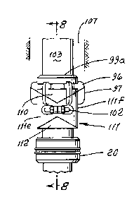
Referring first to Figs. 6 and 26, they show hanger 99
upper, lower and intermediate members 110, 111 and 112 prior
to (Fig. 6) and after (Fig. 26) lateral translation or
expansion of intermediate member 112 relative to upper and
lower members .110 and 111. Simplified schematic view 26'
corresponds to Fig. 26. Such lateral translation is
facilitated by sliding slippage of upward facing upper V-
shaped wedge surfaces llla and 111b on member 111, relative
and with respect to downward facing upper V-shaped wedge
surfaces 110a and 110b on 110; and simultaneous sliding
CA 02780957 2012-05-15
WO 2011/062624 PCT/US2010/002999
12
slippage of downward facing lower inverted V-shaped wedge
surfaces lllc and llld relative and with respect to upward
facing lower inverted V-shaped wedge surfaces 112c and 112d
on 112. This enables downward bodily displacement of 110
relative to and beneath wall casing 103 flange or shoulder
103a previously landed on the top 99a of hanger 99, the
casing then connected in position in the well, whereby
casing loading on the shortened hanger is relieved. This in
turn enables sideward and outward removal of meshing 110 and
111 from beneath member 99.
Note, that member 111 is in two sections, 111c and llld held
in Fig. 6 position (prior to lateral displacement) by a
fastener device or devices, such as bolts 102 that extend
horizontally between the sections lllc and llid. Upon
loosening of those bolts, the downwardly composed weight
effects member sliding, as referred to. A further advantage
of this V-shaped configuration of sliding surfaces is the
maintenance of vertical alignment of the members 110-112,
precluding interference with well structure, at the side or
sides of the hanger structure. Angularity of the V-shaped
member surfaces is typically about 30 relative to
horizontal.
Centering guides 96 and 97 on 99 and 100 serve to center the
hanger in position at the well head.
Accordingly, the members 99, 110 and 111 are then easily
removed, and the mandrel 20 below and supporting member 111
is upwardly removed, whereby the hanger is removed, from
support at 106, leaving the casing 103 projecting upwardly
in the top well zone 107. Support shoulder 106 is typically
CA 02780957 2012-05-15
WO 2011/062624 PCT/US2010/002999
13
provided by outer casing in the well. Accordingly, means is
provided whereby the hanger is expanded laterally and
lengthwise shortened, in response to disconnection of hanger
elements, such as bolt 102 and in response to imposed casing
weight, facilitating ease of removal of the hanger from the
top zone of the well.
Referring now to Figures 1-8, the hanger 10 is generally
tubular, and is shown in its first length configuration. It
may be adjusted to its second and shortened length by
loosening the bolts 102 that clasp together flanges 12a on
the two sections of 111, at opposite sides of axes 90. The
intermediate wedge member sections slide laterally
oppositely along diagonal upper and lower surfaces as
referred to and sections lllc and llld move radially
outwardly. The casing hanger moves to shortened position.
The casing hanger 10 may further comprise the lower
supporting mandrel 20 having rubber O-rings 20a to seal
against casing bore, or outer conductor casing. See bore
150 in Figures 2 and 5. Mandrel 20 may be left in the well
to provide a seal in the annulus between the casing being
hung with the casing hanger 10 and the previously installed
casing string, in which the casing hanger is suspended. The
mandrel is typically bolted to hanger section 112. Figs. 2
and 27 show hanger length dimensions A and B, before and
after hanger adjustment, below casing flange 103a,
As shown in the Figures and described, the
intermediate section 111, is of split construction llla and
111b which allows the hanger to be taken apart in place in
CA 02780957 2012-05-15
WO 2011/062624 PCT/US2010/002999
14
sections, facilitating removal of the hanger from the
cemented casing or tubing, and below casing flange 103a.
Referring now to Figs. 31-37, they show an
alternative form of the hanger 126 that employs vertical
bolts or fasteners 125 rotatable to shorten the hanger
length as from a long measurement A (see Fig. 32) to a short
measurement B (see Fig. 35). This lowers the casing flange
support shoulder 126' on the top of the hanger by amount A-B
below the casing flange 103a, relieving energy or tension in
the initially hanger supported casing 103. Bolts 125 can
easily be removed to allow removal of the hanger upper and
lower elements 110 and 112' described above. Upper element
110' is spaced above element 111'. Bolt adjustment moves
bolt flange 110a' toward bolt flange llla' on llla.
Figs. 31 and 31' show the hanger prior to after
its axial shortening.
Figs. 38-44 correspond to Figs. 31-37,
respectively, and show another alternative form of the
hanger 127 and that employs two or more hydraulic rams,
instead of adjustable bolts, for shortening hanger 127
length as from long measurement A (see Fig. 38) to a short
measurement B (see Fig. 42). A s before, this lowers the
casing flange support shoulder 127' on the top of the
hanger, by amount A-B below the casing flange 103a, thereby
relieving energy or tension in the initially hanger
suspended casing 103. The hydraulic rams include pistons
CA 02780957 2012-05-15
WO 2011/062624 PCT/US2010/002999
135 connected to upper hanger element 310, and projecting
downwardly in cylinders 136 connected to lower hanger
element 312. Pressurized fluid in the cylinders at 313 is
controllably relieved by valve means 314 to allow element
5 310 to be lowered, shorten the hanger. Valve means 314'
controls fluid pressure input to 336. Figs. 41 and 41' show
the hanger prior to and after its axial shortening.
Figs. 45-51, correspond to Figs. 38-44 respectively, and
show a further alternative form of the hanger 140, and that
10 employs an hydraulic jack type means, instead of adjustable
bolts or multiple hydraulic rams, for shortening the hanger
140 length, as from a long measurement A (see Fig. 45) to a
short measurement B (see Fig. 49. This lowers the casing
flange support shoulder 140' on the top of the hanger, by
15 amount A-B below the casing flange 103a, relieving energy or
tension in the initially hanger suspended casing 103. The
jack means includes a cylindrical piston 145 connected to
upper hanger element 140', and projecting downwardly in the
cylinder 146 connected to hanger lower element 147,
corresponding to 112. Pressurized fluid in the cylinder
space 148 is controllably relieved by valve means 149 to
allow element 140 to be lowered to shorten the hanger
allowing upward removal of 140', 146 and 147. Figs. 48 and
48' show the hanger prior to and after axial shortening.
Figs. 52-56 show a retrievable lower bowl assembly
270 which is of generally cylindrical configuration to
receive the hanger lower sealing element, as shown at 20 in
Fig. 6, for sealing. An internal seating shoulder appears
at 271. Downwardly tapered bowl surface is shown at 272.
CA 02780957 2012-05-15
WO 2011/062624 PCT/US2010/002999
16
Figs. 57-61 are like 52-56 and show a retrievable lower bowl
assembly, at 280, and which also is generally cylindrical.
A modified mandrel 20' is received in the bowl assembly and
seats at annular shoulder 282. Mandrel 20' connects to and
is part of the hanger assembly, as described. The bowl
assembly is typically welded to well conductor pipe. Other
attachment means can be used.
Accordingly, the invention provides a retrievable
landing system capable of landing casing string weight
before or during cement jobs. It enables removal of casing
string weight off the landing system which then can be
easily removed and re-used.
Fig. 62 shows a double hung casing installation,
including first means at dual vertical levels or locations
150 and 151 at a well head 152, for supporting larger
diameter hung casing 153 at lower location 150, and for
supporting smaller diameter hung casing 154 at upper
location 151. Structure 157 supported on collar 153a
supports 151.
Each or both of the first means at the locations
150 and 151 may take the form of the devices shown in Figs.
1-8, or Figs. 31-37 or Figs. 38-43, or Figs. 45-51.
Removable surrounding spools are indicated at 160-162.
Second means for controlling releasing energy
stored in the double hung casing, or in each of such
CA 02780957 2012-05-15
WO 2011/062624 PCT/US2010/002999
17
casings, in response to controlled reduction in casing
support, is provided, for example in the adjustments
described above in connection with operation of elements in
said Figures.
Figs. 62 and 63 also show an annular supporting
mandrel 170 extending about the casings, and bodily
relatively movable or slidable on and lengthwise of the
casing, below the double or single hung casing location. As
seen in Figs. 62 and 63, the slidable mandrel carries and is
sealed by O-rings 172, as at 172a with the bore 173 of
structure 174, and by 0-ring 175 as at 175a with the outer
surface 176 of casing 153. That ring is pressurized or
deformed for sealing. A landing shoulder for the mandrel
bevel is provided at 177.
Accordingly, an additional object includes
provision of:
a) a first means providing a double hung casing
installation, at a well head, and characterized by energy
storage in supported casing,
b) and second means for controllably releasing
energy storage in the double hung casing in response to
controlled reduction in casing support, whereby associated
equipment maybe retrieved at the well head, saving time and
expense.
Another object includes provision of adjustable
support structure extending under casing head structure or
structures, and controllably bodily movable out from under
the casing head structure or structures after cementing of
casing lower extent or extents in the well, and after energy
release, as referred to.