Note: Descriptions are shown in the official language in which they were submitted.
CA 2780968 2017-04-19
1
DEVICE FOR DISCHARGING LIQUID OR SUBSTANTIALLY LIQUID PRODUCTS
FROM A COMPRESSIBLE CONTAINER OF FLEXIBLE MATERIAL
Technical field
The present invention relates to a device for discharge of liquid or
substantially liquid
products, preferably foodstuffs, e.g. mayonnaise, mustard, ketchup or
dressing, from a
compressible container made of flexible material.
State of the art
Specification WO 2008/079089 A 1 describes a discharge device whereby products
are fed
out from a plastic bag through a nozzle. The nozzle is provided with a valve
device to
prevent such elements of the product as are, after a discharge, still present
in the nozzle
from dripping out of the nozzle. Providing a nozzle with a fully effective
valve device for this
purpose does however mean that the cost of the nozzle would be high and the
nozzle would
therefore have to be reused, entailing having to clean the nozzle, a time-
consuming and
troublesome procedure. Nor would it ever be possible to be certain that the
cleaning was
done properly so as to meet the high hygiene requirements which apply to
discharge devices
for foodstuffs.
Specification DE 102004038698 B3 describes a discharge device for feeding
products out
from a container of plastic pot type. That discharge device has a compression
device for
squeezing the plastic pot and there is a device which allows the compression
device to
perform return movements. However, that discharge device cannot be used for
feeding
products out from plastic bags, nor does it prevent after-dripping therefrom.
Problem solution
The invention solves the problems of the state of the art by having the
features indicated in
the claims set out below. Said features make it possible for the discharge
device to feed
products out from plastic bags and prevent the occurrence of after-dripping
therefrom.
I I
CA 2780968 2017-04-19
2
List of drawings
Fig. 1 depicts a device according to the invention in a vertical section,
before discharge of a
product from a container placed therein.
Fig. 2 depicts the device according to Fig. 1 during discharge of said product
from the
container.
Fig. 3 depicts the device according to Fig. 1 in a plan view.
Fig. 4 depicts in a side view a container intended to be emptied by a device
according to Fig.
1.
Description of a preferred embodiment of a device according to the invention
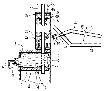
Fig. 1 depicts a device 1 for discharge of liquid or semi-liquid products 2
from a compressible
container 3 made of flexible wall material. The liquid product is preferably a
foodstuff, e.g.
mayonnaise, mustard, ketchup or dressing, and said foodstuff may comprise
quite large
components, e.g. pieces of gherkin. The container 3 may be of plastic bag type
with walls
made of such flexible material that it can be squeezed without bursting.
The discharge device 1 has a compression device 4 and a manually operable
operating
device 5 which can be subjected to operating movements in order to operate the
compression device 4 with the object of squeezing the plastic bag 3 in order
to feed the
product 2 out through a nozzle 6. The compression device 4 is disposed with
respect to an
outer container 7 and comprises a fixed compression means 8 and a movable
compression
means 9. The fixed compression means 8 is firmly attached to the outer
container 7 and the
lower compression means 9 is disposed in the latter in such a way as to be
movable in the
height direction. The plastic bag 3 is placeable between said compression
means 8 and 9.
A housing 10 is placed on top of the outer container 7.
I I
CA 2780968 2017-04-19
3
The operating device 5 has a device 11 resembling a pair of tongs, with two
limbs 12, 13, the
limb 12 being firmly disposed on the housing 10 and the limb 13 being
pivotably connected to
the limb 12 via a hinge pin 14 which supports a spring 15 which abuts against
the insides of
the limbs 12, 13 so that it pushes them apart and keeps them apart after being
operated.
The forward portion 13a of the limb 13 has a stud 16 intended to transmit the
operating
movements of the operating device 5 to the compression device 4 via an opening
30 of the
housing 10 (see Fig 1).
The compression device 4 has also a piston 17 or equivalent, which is disposed
vertically
and extends through the housing 10 and down into the outer container 7. This
piston 17 is
more precisely supported for vertical movement in upper portions 18 and lower
portions 19 of
the housing 10, extends movably vertically through the upper compression means
8 of the
outer container 7 and has at the bottom the lower compression means 9 fastened
to it by
nuts 20, 21 or similar fastening means.
The portion of the piston 17 which is within the housing 10 extends through a
movement
transmission means 22 and a coil compression spring 23 which abuts at the
bottom against
the movement transmission means 22 and at the top against a portion 25 of the
housing 10,
possibly via a washer 24.
Discharge of a portion of product 2 from the plastic bag 3 is effected by
taking hold of the
limbs 12, 13 and pressing the limb 13 downwards towards the limb 12 in a
portioning
direction P1 (see Fig. 2). This causes the forward portions 13a of the limb 13
to pivot in an
upward direction P2 with the result that the stud 16 moves the movement
transmission
means 22 from a releasing position F (see Fig. 1) to a locking position L (see
Fig. 2). In the
releasing position F the means 22 allows the piston 17 to move relative to it
in vertical
directions, whereas in the locking position it is firmly locked to the piston
17 by clamping,
enabling it to move the piston 17 in an portioning direction P3. Moving the
piston 17 in the
portioning direction P3 causes the lower compression means 9 firmly attached
to the piston
to move in the same direction P3 and to squeeze the plastic bag 3 so that a
portion 2a of the
product 2 is discharged therefrom through the nozzle 6.
I I
CA 2780968 2017-04-19
4
When the movement transmission means 22 causes the piston 17 to move in the
portioning
direction P3 the coil compression spring 23 is tightened, and when the limb 13
is released
after the discharge of the portion 2a the coil compression spring 23 will push
the movement
transmission means 22 back to its releasing position F.
A device 29 which allows return movement is adapted to allowing the
compression means 9,
after having been subjected to a movement in the portioning direction P3, to
perform a return
movement in a return direction P4 which is opposite to the portioning
direction P3 and is
therefore in this case directed downwards. During this movement in the return
direction P4,
the movable compression means 9 will move in the same direction P4, i.e. in
this case
downwards, which means that the plastic bag 3 expands or may expand somewhat,
thereby
causing its interior to become somewhat larger, with the result that the
pressure in the nozzle
6 ceases and such elements 2b of the product 2 as are present therein are
prevented from
dripping out of it. Depending on the degree of expansion of the plastic bag 3,
the return
movement may even result in elements 2b of the product 2 which are still in
the nozzle being
sucked in towards the plastic bag 3.
In the embodiment depicted, the device 29 which allows the return movement has
two stop
surfaces 27, 28 disposed above one another and, between them, at least one
ring 29a or an
equivalent means threaded on the piston 17. The stop surface 28 may for
example take the
form of the inside of the upper portion 18 of the housing, and the stop
surface 27 takes the
form of the upper side of such a portion 25 of the housing 10 as is situated
below the upper
portion 18. The ring 29a has resilient characteristics and can by friction
between it and the
piston 17 accompany the movement of the piston and thus be moved by the piston
17
between the stop surfaces 27, 28 when the piston 17 moves upwards or
downwards. When
the piston 17 is caused to move upwards in the portioning direction P3, the
ring 29a thus
accompanies it and is moved from the stop surface 27 to the stop surface 28
which brings to
a halt the upward movement of the ring 29a. When the ring 29a has reached the
stop
surface 28, the friction between it and the piston 17 allows the piston 17 to
slide in the ring
29a and continue moving upwards in the portioning direction P3. When the
piston 17 is no
longer being caused to move upwards in the portioning direction P3, it can
move downwards
in the return direction P4 until the ring 29a, by its friction against the
piston 17, brings the
CA 2780968 2017-04-19
movement of the piston to a halt when it comes into contact with the stop
surface 27. Hence,
in one aspect, the ring 29a grips round the piston 17 by spring action.
The return movement in the return direction P4 may be effected by means of the
plastic bag
5 3. Thus the weight of the plastic bag 3 with product 2 therein may be
utilised to press down
the lower compression means 9, the piston 17 and the ring 29a so that all
three are
subjected to the return movement in the return direction P4. The more product
2 is dis-
charged from it, the lighter the plastic bag 3 becomes, and if the weight of
the plastic bag 3 is
no longer sufficient its elastic characteristics causing it to endeavour to
revert to its original
shape may instead be utilised to exert such a force on the lower compression
means 9, the
piston 17 and the ring 29a that they move downwards in the return direction
P4. The more
the plastic bag 3 is squeezed, the greater will be the strength of its
endeavour to revert to its
original shape, which can thus be utilised to effect the movement in the
return direction P4.
The magnitude S of the return movement is determined by the distance between
the ring 29a
and, for example, the stop surface 28, as in the embodiment depicted. Said
magnitude S
may however be some other magnitude and be varied as necessary, e.g. by
providing a
thicker or thinner ring 29a than that depicted, by providing more than one
ring 29a or by
altering the distance A between the stop surfaces 27, 28. It is also possible
for the stop
surfaces 27, 28 to be situated on parts whose mutual spacing A is variable.
To make it possible for the plastic bag 3 to be placed in the outer container
7 between the
compression means 8, 9, the outer container 7 has a lower aperture 32 and the
length of the
piston 17 is with advantage such that the lower compression means 9 can be
drawn far
enough out from the outer container 7 through its lower aperture 32 to enable
the plastic bag
to be put into the outer container 7 via the lower aperture 32 without the
piston 17 having to
be drawn out from the housing 10. The plastic bag 3 is introduced into the
outer container 7
until it abuts against the upper compression means 8, after which the lower
compression
means 9 is put back into the outer container 7 until it abuts against the
plastic bag 3.
In the embodiment depicted, the plastic bag 3 has an inner connecting portion
31 disposed
within it. The nozzle 6 has a connecting portion 6a so configured that it is
possible to use it
I I
CA 2780968 2017-04-19
6
for opening the plastic bag 3 and thereafter for connecting the nozzle 6
firmly to the inner
connecting portion of the plastic bag 3. The nozzle 6 thus has both an opening
function and
a connecting function.
The outer container 7 may have at the top a lateral aperture 33 through which
the nozzle 6 or
portions of the plastic bag 3 which comprise the nozzle 6 may be caused to
protrude from the
outer container 7. The outer container 7 may have on the outside below the
lateral aperture
33 a bracket 34 forming a hollow 35 both for the portions of the plastic bag 3
which comprise
the inner connecting portion 31 and for the nozzle 6 so that said bracket 34
holds firmly the
portions of the plastic bag 3 which comprise the inner connecting element 31,
and also the
nozzle 6.
The device 29 which allows return movement makes it possible to use nozzles
without drip-
preventing valves, thereby making it possible for the nozzles to have very
simple shapes and
be manufactured at such a low price that they are suitable for once-only use,
i.e. when a
plastic bag with nozzle is empty it is removed together with its nozzle and a
full plastic bag
with a new nozzle is inserted and is thereafter emptied by means of the device
1.
The invention is not limited to the variants described above and depicted in
the drawings but
may be varied within the scope of the claims set out below. Examples of
further variants
which may be cited are the compression device possibly having two movable
compression
means instead of one, the configuration of the operating device possibly being
other than
resembling a pair of tongs, and the device effecting return movements possibly
comprising
for example two mutually cooperating means connected to one another with such
play that a
return movement can take place between them.
The outer container 7 need not be of upright type but may be adapted to being
held in the
hand during discharge. The outer container 7 as seen in plan view (see Fig. 3)
may have
two parallel walls 7a, 7b and the piston 17 may be disposed near to one wall
7a.
The nozzle may also be of some other type than as depicted. Thus the nozzle
may be
formed by the container, viz, by two opposite wall portions of the latter
which extend along a
container side between them forming a discharge duct which allows discharge of
product
CA 2780968 2017-04-19
7
from the container. Said opposite wall portions may be folded out from the
side of the
container to form a nozzle pointing outwards from the container, and if said
discharge duct is
initially closed it can be opened when discharge of product from the container
is to take
place.
It may also be mentioned that a movable compression means in the compression
device
may have a collar (e.g. a collar 9a as depicted in Fig. 1) which is directed
towards a space
for the container of product and which abuts against the inside of an outer
container in which
said container is placeable. This collar is intended to prevent the walls of
the container from
being pressed in between said inner wall and the compression means and thereby
being
firmly clamped.