Note: Descriptions are shown in the official language in which they were submitted.
CA 02,811982[12-05- 7
WO 2011/063970 PCT/EP2010/007178
1
AN ELECTRICALLY HEATED SMOKING SYSTEM
WITH INTERNAL OR EXTERNAL HEATER
The present invention relates to an electrically heated smoking system
including a heater for
heating an aerosol-forming substrate.
EP-A-0 358 002 discloses a smoking system comprising a cigarette with a
resistance
heating element for heating tobacco material in the cigarette. The cigarette
has an electrical
connection plug for connection to a reusable, hand held controller. The hand
held controller
includes a battery and a current control circuit which controls the supply of
power to the resistance
heating element in the cigarette.
One problem of such a proposed smoking system is that tobacco smoke tends to
condense
on the internal walls of the system. This is undesirable because condensation
build up on the
internal walls of the system can lead to reduced performance.
Accordingly, it is advantageous to provide an electrically heated smoking
system which, in
use, minimises the risk of smoke or aerosol condensation on its internal
walls.
According to the invention, there is provided an electrically heated smoking
system for
receiving an aerosol-forming substrate, the system comprising a heater for
heating the substrate to
form the aerosol, the heater comprising a heating element, wherein the
electrically heated smoking
system and the heating element are arranged such that, when the aerosol-
forming substrate is
received in the electrically heated smoking system, the heating element
extends a distance only
partially along the length of the aerosol forming-substrate, and the heating
element is positioned
towards the downstream end of the aerosol-forming substrate.
According to another aspect of the invention, there is provided an
electrically heated
smoking system for receiving an aerosol-forming substrate, the system
comprising a heater for
heating the substrate to form the aerosol, the heater comprising a heating
element, wherein the
electrically heated smoking system and the heating element are arranged such
that, when the
aerosol-forming substrate is received in the electrically heated smoking
system, the heating
element extends a distance only partially along the length of the aerosol
forming-substrate.
According to a further aspect of the invention, there is provided an
electrically heated
smoking system for receiving an aerosol-forming substrate, the system
comprising a heater for
heating the substrate to form the aerosol, the heater comprising a heating
element, wherein the
electrically heated smoking system and the heating element are arranged such
that, when the
aerosol-forming substrate is received in the electrically heated smoking
system, the heating
element is positioned towards the downstream end of the aerosol-forming
substrate.
Positioning the heating element such that it extends only partially along the
aerosol-forming
CA 02781198 2012 05 17
WO 2011/063970 PCT/EP2010/007178
2
substrate's length reduces the power required to heat the substrate and
produce the aerosol.
Furthermore, positioning the heating element towards the downstream end of the
aerosol-
forming substrate also minimises the risk of condensation of the aerosol on
the internal walls of the
smoking system. This is because the non-heated portion of the aerosol-forming
substrate (for
example, a tobacco rod) located away from the heating element acts as a
filtration zone, thereby
minimising the risk of aerosol leaving the upstream end of the aerosol forming
substrate.
In addition, positioning the heating element towards the downstream end of the
aerosol-
forming substrate shortens the zone contained between the downstream end of
the heating
element and the downstream end of the aerosol-forming substrate. This leads to
a significant
reduction in the energy required to generate an aerosol for the user. This
also leads to a reduction
in the time to first puff, that is to say, the time between energizing the
heating element and
providing the aerosol to a user.
The heating element may be an external heating element. Preferably, the
heating element
extends fully or partially around the circumference of the aerosol forming
substrate. In one
embodiment, the heating element extends substantially fully around the
circumference of the
aerosol forming substrate.
Alternatively, the heating element may be an internal heating element. In one
embodiment,
the heating element is arranged to be inserted into the aerosol forming
substrate. The internal
heating element may be positioned at least partially within or inside the
aerosol forming substrate.
Preferably, the aerosol-forming substrate is substantially cylindrical in
shape. The aerosol-
forming substrate may be substantially elongate. The aerosol-forming substrate
may also have a
length and a circumference substantially perpendicular to the length.
Preferably, the electrically
heated smoking system comprises an aerosol-forming substrate in which the
length of the aerosol-
forming substrate is substantially parallel to airflow direction in the
electrically heated smoking
system.
Preferably, the electrical energy is supplied to the heating element (or, in
embodiments
where further heating elements are included, to one or more of the heating
elements) until the
heating element or elements reach a temperature of between approximately 250
C and 440 C.
Any suitable temperature sensor and control circuitry may be used in order to
control heating of the
heating element or elements to reach the temperature of between approximately
250 C and
440 C. This is in contrast to conventional cigarettes in which the combustion
of tobacco and
cigarette wrapper may reach 800 C.
The upstream and downstream ends of the electrically heated smoking system are
defined
with respect to the airflow when the user takes a puff. Typically, incoming
air enters the electrically
heated smoking system at the upstream end, combines with the aerosol, and
carries the aerosol in
CA 02'81198 2C12 05 7
WO 2011/063970 PCT/EP2010/007178
3
the airflow towards the user's mouth at the downstream end. As known to those
skilled in the art,
an aerosol is a suspension of solid particles or liquid droplets or both solid
particles and liquid
droplets in a gas, such as air.
Preferably, the substrate forms part of a separate smoking article and the
user may puff
directly on the smoking article. The smoking article may be substantially
cylindrical in shape. The
smoking article may be substantially elongate. The smoking article may have a
length and a
circumference substantially perpendicular to the length. The smoking article
may have a total length
between approximately 30 mm and approximately 100 mm. The smoking article may
have an
external diameter between approximately 5 mm and approximately 12 mm. The
smoking article
may comprise a filter plug. The filter plug may be located at the downstream
end of the smoking
article. The filter plug may be a cellulose acetate filter plug. The filter
plug is preferably
approximately 7 mm in length, but may have a length of between approximately 5
mm to
approximately 10 mm.
Preferably, the smoking article is a cigarette. In a preferred embodiment, the
smoking article
has a total length of approximately 45 mm. It is also preferable for the
smoking article to have an
external diameter of approximately 7.2 mm. Preferably, the aerosol forming
substrate comprises
tobacco. Further, the aerosol forming substrate may have a length of
approximately 10 mm.
However it is most preferable for the aerosol-forming substrate to have a
length of approximately
12 mm. Further, the diameter of the aerosol forming substrate may also be
between approximately
mm and approximately 12 mm. The smoking article may comprise an outer paper
wrapper.
Further, the smoking article may comprise a separation between the aerosol-
forming substrate and
the filter plug. The separation may be approximately 18 mm, but may be in the
range of
approximately 5 mm to approximately 25 mm.
The heating element being positioned towards the downstream end of the aerosol-
forming
substrate may be defined as the separation between the downstream end of the
heating element
and the downstream end of the aerosol-forming substrate, being less than the
separation between
the upstream end of the heating element and the upstream end of the aerosol-
forming substrate.
Preferably, the downstream end of the heating element is upstream of the
downstream end
of the aerosol-forming substrate by a distance d equal to, or greater than,
approximately 1 mm. By
having a distance d of greater than, or equal to approximately 1mm (rather
than having d = 0), this
avoids the heater being immediately adjacent the non-aerosol forming part of
the smoking article,
such as the non-tobacco part of the cigarette (with the exception of the
cigarette paper)
downstream to the tobacco plug. This reduces heat dissipation through non-
tobacco materials.
Furthermore, this gap allows a reduction of mainstream smoke temperature.
Preferably, the upstream end of the heating element is downstream of the
upstream end of
CA 02781198 2012-05-17
WO 2011/063970 PCT/EP2010/007178
4
the aerosol-forming substrate by a distance e between approximately 2 mm and
approximately 6
mm. Even more preferably, the upstream end of the heating element is
downstream of the
upstream end of the aerosol-forming substrate by a distance e of approximately
4 mm.
The non-heated portion of the aerosol-forming substrate located at the
upstream end, that
is, between the upstream end of the aerosol-forming substrate and the upstream
end of the heating
element, provides an efficient filtration zone. This minimises the risk of
aerosol leaving the
upstream end of the aerosol forming substrate in the electrically heated
smoking system. This also
minimises the risk of condensation of aerosol inside the electrically heated
smoking system, which
minimises the number of cleaning operations required throughout the smoking
system's lifetime. In
addition, the non-heated upstream portion of the aerosol-forming substrate
acts as a slow-release
aerosol reservoir which may be accessible by thermal conduction through the
substrate throughout
the smoking experience.
Preferably, the ratio of the distance w, that the heating element extends
along the aerosol-
forming substrate, to the length / of the aerosol-forming substrate, ¨w is
between approximately 0.35
and approximately 0.6. Even more preferably, the ratio ¨w is approximately
0.5.
The ratio of ¨w of between approximately 0.35 and approximately 0.6 has the
advantage
that it maximises the volume of aerosol delivered to the user, whilst
minimising the amount of
aerosol leaving the upstream portion of the aerosol forming substrate. This
minimises the risk of
condensation of the aerosol in the smoking system. Further, this ratio also
has the advantage that it
minimises heat loss through non-tobacco materials. This means that the smoking
system requires
less energy.
Even more preferably, the ratio of the distance that the heating element
extends along the
aerosol-forming substrate to the length of the aerosol-forming substrate is
approximately 0.5. A
ratio of approximately 0.5 (for an aerosol forming substrate such as a tobacco
plug of either 10 or
12 mm) offers the best balance in terms of aerosol deliveries, minimisation of
the risk of aerosol
leaving the upstream end of the aerosol forming substrate and aerosol
temperature.
In one embodiment of the electrically heated smoking system, the heater
further comprises
a second heating element arranged, when the aerosol-forming substrate is
received in the
electrically heated smoking system: to extend a distance y only partially
along the length / of the
aerosol-forming substrate; and to be upstream of the first heating element.
The first heating
element, the second heating element or both heating elements may extend
substantially partially or
fully around the circumference of the aerosol forming substrate.
CA 02'81198 2C12 05 17
WO 2011/063970 PCT/EP2010/007178
In another embodiment, the heater further comprises a second heating element
arranged,
when the aerosol-forming substrate is received in the electrically heated
smoking system, to extend
a distance y only partially along the length / of the aerosol-forming
substrate.
Providing a second heating element upstream of the first heating element
allows different
parts of the aerosol-forming substrate to be heated at different times. This
is also advantageous,
since the aerosol-forming substrate does not need to be reheated for example
if the user wishes to
stop and resume the smoking experience. In addition, providing two separate
heating elements
provides for more straightforward control of the temperature gradient along
the aerosol-forming
substrate and hence control of the aerosol generation. Preferably, the heating
elements are
independently controllable.
Further heating elements may be provided between the first and second heating
elements.
For example, the heater may comprise three, four, five, six or more heating
elements.
Preferably, the separation between the first heating element and the second
heating
element is equal to or greater than approximately 0.5 mm. That is to say
preferably, the separation
between the upstream end of the first heating element and the downstream end
of the second
heating element is equal to or greater than approximately 0.5 mm. However, any
separation
between the first and second heating elements may be used, provided the first
and second heating
elements are not in electrical contact with each other.
Preferably, the upstream end of the second heating element is downstream of
the upstream
end of the aerosol-forming substrate by a distance g between approximately 2
mm and
approximately 4 mm. Even more preferably, the upstream end of the second
heating element is
downstream of the upstream end of the aerosol-forming substrate by a distance
g of approximately
3 mm.
Again, the non-heated portion of the aerosol-forming substrate located at the
upstream end,
that is, between the upstream end of the aerosol-forming substrate and the
upstream end of the
second heating element, provides an efficient filtration zone. This minimises
the risk of aerosol
escaping from the upstream end of the aerosol forming substrate in the
electrically heated smoking
system. This also minimises the risk of condensation of aerosol inside the
electrically heated
smoking system, which minimises the number of cleaning operations required
throughout the
electrically heated smoking system's lifetime. In addition, the non-heated
upstream portion of the
aerosol-forming substrate acts as a slow-release aerosol reservoir which may
be accessible by
thermal conduction through the substrate throughout the smoking experience.
For embodiments of the invention which have two heating elements, the lengths
of both the
heating elements may be slightly reduced (compared to the length of the
heating element in
embodiments of the invention which only have one heating element) in order to
keep a zone
CA 02'81198 2C12 05 7
WO 2011/063970 PCT/EP2010/007178
6
upstream of the second heating element which is cooler than the heated portion
of the aerosol
forming substrate, and a zone downstream of the first heating element which is
cooler than the
heated portion of the aerosol forming substrate. That is to say, for
embodiments of the invention
which only have a single heating element, the heating element may have a
length of approximately
4mm. Then, for embodiments of the invention which having two heating elements,
the length of
each heating element may be reduced to approximately 3mm, for example. A
decrease in length
may be compensated by a higher electrically power.
Alternatively, the first heating element (downstream) may have substantially
the same
dimension as the heating element in the smoking system which only has a single
heating element,
but the second heating element (upstream) may be shorter in length than the
first heating element.
That is to say, the first heating element has a length which is greater than
the length of the second
heating element. For example, the first heating element may have a length of
approximately 4 mm,
while the second heating element may have a length of approximately 3 mm.
This means that substantially equal aerosol yields and time to first puff are
provided by the
first and second heating elements.
Preferably, the ratio of the distance (x + y) that the first heating element
and the second
heating element together extend along the aerosol-forming substrate, to the
length / of the aerosol-
forming substrate (x + y) is between approximately 0.5 and approximately 0.8.
(x +y)
The inventors have found that this range of the ratio
maximises the advantages of
the smoking experience. This ratio has the advantage that it maximises the
aerosol delivery
amount, whilst minimising the amount of aerosol escaping from the upstream
portion of the aerosol
forming substrate. This minimises the risk of condensation of the aerosol
within the smoking
system. Further, this ratio also has the advantage that it minimises heat loss
through non-tobacco
materials. This means that the smoking system requires less energy. A ratio of
approximately 0.7
(for a tobacco plug of either 10 mm or 12 mm) offers the best balance in terms
of aerosol deliveries,
minimising the risk of aerosol leaving the upstream end of the aerosol forming
substrate and
aerosol temperature.
Each heating element may be in the form of a ring extending substantially
partially or fully
around the circumference of the aerosol-forming substrate. Preferably, the
position of each heating
element is fixed with respect to the electrically heated smoking system and
hence the aerosol-
forming substrate. Preferably, the heater does not include an end portion to
heat the upstream end
of the aerosol-forming substrate. This provides a non-heated portion of
aerosol-forming substrate at
the upstream end.
CA 02781198 2012-05-17
WO 2011/063970 PCT/EP2010/007178
7
Each heating element preferably comprises an electrically resistive material.
Each heating
element may comprise a non-elastic material, for example a ceramic sintered
material, such as
alumina (A1203) and silicon nitride (Si3N4), or printed circuit board or
silicon rubber. Alternatively,
each heating element may comprise an elastic, metallic material, for example
an iron alloy or a
nickel-chromium alloy.
Other suitable electrically resistive materials include but are not limited
to: semiconductors
such as doped ceramics, electrically "conductive" ceramics (such as, for
example, molybdenum
disilicide), carbon, graphite, metals, metal alloys and composite materials
made of a ceramic
material and a metallic material. Such composite materials may comprise doped
or undoped
ceramics. Examples of suitable doped ceramics include doped silicon carbides.
Examples of
suitable metals include titanium, zirconium, tantalum and metals from the
platinum group.
Examples of suitable metal alloys include stainless steel, nickel-, cobalt-,
chromium-, aluminium-
titanium- zirconium-, hafnium-, niobium-, molybdenum-, tantalum-, tungsten-,
tin-, gallium- and
manganese- alloys, and super-alloys based on nickel, iron, cobalt, stainless
steel, Timetal and
iron-manganese-aluminium based alloys. Timetale is a registered trade mark of
Titanium Metals
Corporation, 1999 Broadway Suite 4300, Denver, Colorado. In composite
materials, the electrically
resistive material may optionally be embedded in, encapsulated or coated with
an insulating
material or vice-versa, depending on the kinetics of energy transfer and the
external
physicochemical properties required.
Alternatively, each heating element may comprise an infra-red heating element,
a photonic
source, or an inductive heating element.
Each heating element may comprise a heat sink, or heat reservoir comprising a
material
capable of absorbing and storing heat and subsequently releasing the heat over
time to the
aerosol-forming substrate. The heat sink may be formed of any suitable
material, such as a suitable
metal or ceramic material. Preferably, the material has a high heat capacity
(sensible heat storage
material), or is a material capable of absorbing and subsequently releasing
heat via a reversible
process, such as a high temperature phase change. Suitable sensible heat
storage materials
include silica gel, alumina, carbon, glass mat, glass fibre, minerals, a metal
or alloy such as
aluminium, silver or lead, and a cellulose material such as paper. Other
suitable materials which
release heat via a reversible phase change include paraffin, sodium acetate,
naphthalene, wax,
polyethylene oxide, a metal, metal salt, a mixture of eutectic salts or an
alloy.
The aerosol-forming substrate preferably comprises a tobacco-containing
material
containing volatile tobacco flavour compounds which are released from the
substrate upon heating.
Alternatively, the aerosol-forming substrate may comprise a non-tobacco
material.
Preferably, the aerosokforming substrate further comprises an aerosol former.
Examples of
CA 02,811982[12-05- 7
WO 2011/063970 PCT/EP2010/007178
8
suitable aerosol formers are glycerine and propylene glycol.
In one embodiment, the aerosol-forming substrate is a solid or substantially
solid substrate.
The solid substrate may comprise, for example, one or more of: powder,
granules, pellets, shreds,
spaghettis, strips or sheets containing one or more of: herb leaf, tobacco
leaf, fragments of tobacco
ribs, reconstituted tobacco, homogenised tobacco, extruded tobacco and
expanded tobacco. The
solid substrate may be provided as a cylindrical plug of aerosol-forming
substrate. Alternatively, the
solid substrate may be provided in a suitable container or cartridge.
Optionally, the solid substrate
may contain additional tobacco or non-tobacco volatile flavour compounds, to
be released upon
heating of the substrate.
Optionally, the solid substrate may be provided on or embedded in a thermally
stable
carrier. The carrier may take the form of powder, granules, pellets, shreds,
spaghettis, strips or
sheets. Alternatively, the carrier may be a tubular carrier having a thin
layer of the solid substrate
deposited on its outer surface, or on both its inner and outer surfaces. Such
a tubular carrier may
be formed of, for example, a paper, or paper like material, a non-woven carbon
fibre mat, a low
mass open mesh metallic screen, or a perforated metallic foil or any other
thermally stable polymer
matrix. The solid substrate may be deposited on the surface of the carrier in
the form of, for
example, a sheet, foam, gel or slurry. The solid substrate may be deposited on
the entire surface of
the carrier, or alternatively, may be deposited in a pattern in order to
provide a non-uniform flavour
delivery during use.
Alternatively, the carrier may be a non-woven fabric or fibre bundle into
which tobacco
components have been incorporated. The non-woven fabric or fibre bundle may
comprise, for
example, carbon fibres, natural cellulose fibres, or cellulose derivative
fibres.
The aerosol-forming substrate may alternatively be a liquid substrate. If a
liquid substrate is
provided, the electrically heated smoking system preferably comprises means
for retaining the
liquid. For example, the liquid substrate may be retained in a container.
Alternatively or in addition,
the liquid substrate may be absorbed into a porous carrier material. The
porous carrier material
may be made from any suitable absorbent plug or body, for example, a foamed
metal or plastics
material, polypropylene, terylene, nylon fibres or ceramic. The liquid
substrate may be retained in
the porous carrier material prior to use of the electrically heated smoking
system or alternatively,
the liquid substrate material may be released into the porous carrier material
during, or immediately
prior to use. For example, the liquid substrate may be provided in a capsule.
The shell of the
capsule preferably melts upon heating and releases the liquid substrate into
the porous carrier
material. The capsule may optionally contain a solid aerosol forming substrate
in combination with
the liquid.
Alternatively, or in addition, if the aerosol-forming substrate is a liquid
substrate, the
CA 02781198 2012 05 17
WO 2011/063970 PCT/EP2010/007178
9
electrically heated smoking system may further comprise an atomiser in contact
with the liquid
substrate source and including the heating element or elements. The atomiser
converts the liquid
into an aerosol or fine mist of particles. The atomiser may comprise a liquid
source connected to a
tube. The tube may be heated by an electrical heater in close proximity to the
tube, or in contact
with the tube. The liquid is atomised when the tube is heated by the heater
when electrical energy
is passed through the heater.
In addition to the heating element or elements, the atomiser may include one
or more
electromechanical elements such as piezoelectric elements. Additionally or
alternatively, the
atomiser may also include elements that use electrostatic, electromagnetic or
pneumatic effects.
The electrically heated smoking system may still further comprise a
condensation chamber.
The aerosol-forming substrate may alternatively be any other sort of
substrate, for example,
a gas substrate, or any combination of the various types of substrate. During
operation, the
substrate may be completely contained within the electrically heated smoking
system. In that case,
a user may puff on a mouthpiece of the electrically heated smoking system.
Alternatively, during
operation, the substrate may be partially contained within the electrically
heated smoking system. In
that case, the substrate may form part of a separate smoking article and the
user may puff directly
on the smoking article.
Preferably, the electrically heated smoking system further comprises a power
supply for
supplying power to the heating element or elements. The power supply may be
any suitable power
supply, for example a DC voltage source. In one embodiment, the power supply
is a Lithium-ion
battery. Alternatively, the power supply may be a Nickel-metal hydride battery
or a Nickel cadmium
battery.
Preferably, the electrically heated smoking system further comprises
electronic circuitry
arranged to be connected to the power supply and the heating element or
elements. If more than
one heating element is provided, preferably the electronic circuitry provides
for the heating
elements to be independently controllable. The electronic circuitry may be
programmable.
In one embodiment, the system further comprises a sensor to detect air flow
indicative of a
user taking a puff. The sensor may be an electro-mechanical device.
Alternatively, the sensor may
be any of: a mechanical device, an optical device, an opto-mechanical device
and a micro electro
mechanical systems (MEMS) based sensor. In that embodiment, preferably, the
sensor is
connected to the power supply and the system is arranged to activate the
heating element or
elements when the sensor senses a user taking a puff. In an alternative
embodiment, the system
further comprises a manually operable switch, for a user to initiate a puff.
Preferably, the system further comprises a housing for receiving the aerosol-
forming
substrate and designed to be grasped by a user.
Ck 02'81198 2[12-05-17
WO 2011/063970 PCT/EP2010/007178
Features described in relation to one aspect of the invention may also be
applicable to
another aspect of the invention.
The invention will be further described, by way of example only, with
reference to the
accompanying drawings, in which:
Figure 1 is a schematic diagram showing a first embodiment of the electrically
heated
smoking system in use with a smoking article;
Figure 2 is a schematic diagram showing a second embodiment of the
electrically heated
smoking system in use with a smoking article;
Figure 3 is a detailed view of a cross-section of an external heating element
according to
one embodiment of the invention, which may be used in conjunction with Figure
1 or Figure 2;
Figure 4 is a detailed view of an external heating element laid out flat
according to one
embodiment of the invention, which may be used in conjunction with Figure 1 or
Figure 2;
Figure 5 is a detailed view of an external heating element laid out flat
according to another
embodiment of the invention, which may be used in conjunction with Figure 1 or
Figure 2; and
Figures 6 to 11 show a method for forming an internal heater according to one
embodiment
of the invention.
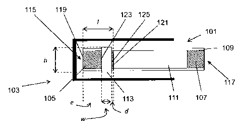
Figure 1 shows a smoking article 101 received in an electrically heated
smoking system 103
according to a first embodiment of the invention. In this embodiment, the
smoking article 101 has
an elongate cylindrical shape and comprises an aerosol-forming substrate 105,
and a filter plug
107, arranged sequentially and in coaxial alignment. The components 105 and
107 are
overwrapped with an outer paper wrapper 109. In this embodiment, the aerosol-
forming substrate
105 is in the form of a cylindrical plug of solid substrate. The length I of
the plug is substantially
parallel to the length of the smoking article and also substantially parallel
to the direction of airflow
(not shown) in the electrically heated smoking system when a user puffs on the
smoking article.
The circumference of the plug is substantially perpendicular to the length.
The filter plug 107 is
located at the downstream end of the smoking article 101 and, in this
embodiment, is separated
from the aerosol-forming substrate 105 by separation 111.
As already discussed, various types of smoking article may be used in the
context of the
present invention. The smoking article does not need to be of the form
illustrated in Figure 1. In
particular, the smoking article does not have to have a length of aerosol-
forming substrate which is
substantially perpendicular to its circumference.
In the first embodiment illustrated in Figure 1, the electrically heated
smoking system 103
comprises a heater having a heating element 113. The heating element is
resistive, and heats up
as electrical current is passed through the heating element. In this
embodiment, the heating
element 113 is in the form of a ring, having a width wand a diameter h.
CA 2781198 2017-04-03
11
In Figure 1, the upstream end of the smoking article 101 is labelled 115,
while the
downstream end of the smoking article is labelled 117. Further, the upstream
end of the aerosol-
forming substrate is labelled 119, while the downstream end of the aerosol-
forming substrate is
labelled 121. Finally, the upstream end of the heating element is labelled
123, while the
downstream end of the heating element is labelled 125.
In an alternative embodiment, the heater may be an internal heater. An
internal heater is
one which is placed within the aerosol forming substrate, for example as
described in our co-
pending European Patent Application No. 09252501.3, filed 29 October 2009.
The internal heater may be manufactured as described
below with reference to Figures 6 to 11.
In an alternative embodiment the heater may comprise a temperature sensor used
as an
internal heater which is placed inside the aerosol-forming substrate. An
example of a suitable
internal heater is a PT resistive temperature sensor which may be used as an
internal heater. The
PT resistive temperature sensor may be made by Heraeus Sensor Technology,
Reinhard-Heraeus-
Ring, 23D-63801, Kleinostheim, Germany.
In the case of both internal and external heaters the heating element 113
extends only
partially along the length / of the cylindrical plug of aerosol-forming
substrate 105. That is to say,
the width w of the heating element 113 is less than the length / of the plug
of aerosol-forming
substrate 105. The heating element 113 is positioned towards the downstream
end 121 of the
aerosol-forming substrate 105.
In the embodiment illustrated in Figure 1, the downstream end 125 of the
heating element
113 is upstream of the downstream end 121 of the cylindrical plug of aerosol-
forming substrate
105. In this embodiment, the separation between the downstream end 125 of the
heating element
113 and the downstream end 121 of the cylindrical plug of aerosol-forming
substrate 105 is d. Also
in this embodiment, the upstream end 123 of the heating element 113 is
downstream of the
upstream end 119 of the cylindrical plug of aerosol-forming substrate 105. In
this embodiment, the
separation between the upstream end 123 of the heating element 113 and the
upstream end 119 of
the cylindrical plug of aerosol-forming substrate 105 is e.
The inventors of the present invention have found the various dimensions of
the heating
element 113 and the plug of aerosol-forming substrate 105, as well as the
relative positions of the
heating element 113 and the plug of aerosol-forming substrate 105, can be
adjusted to substantially
improve the smoking experience. In particular, the time to first puff can be
reduced. That is to say,
the time between the heating element being activated and the user being able
to take a first puff on
the smoking article can be reduced. In addition, the power required to
generate the aerosol and
sustain that aerosol generation can be reduced. In addition, this minimises
the risk of aerosol
CA 02'81198 2C12 05 7
WO 2011/063970 PCT/EP2010/007178
12
leaving the upstream portion of the aerosol forming substrate. Furthermore,
condensate and other
residues forming on the inside of the electrically heated smoking system can
be minimised, which
minimises cleaning required.
As already mentioned, the heating element 113 is positioned towards the
downstream end
of the aerosol-forming substrate 105. That is to say, d < e. For an aerosol-
forming substrate
containing tobacco, positioning the heating element 113 towards the downstream
end of the
aerosol-forming substrate 105 shortens the tobacco filtration zone contained
between the
downstream end of the heating element 113 and the downstream end of the plug
of aerosol-
forming substrate 105 (that is to say, reduces d). This leads to a significant
reduction of the energy
required to generate a pleasant smoke and similarly leads to a reduction of
the time to first puff.
However, it is preferable for d not to be reduced to zero, as previously
described. In fact, it has
been found that, in order to maximise the advantages of the smoking
experience, the separation
between the downstream end of the heating element 113 and the downstream end
of the cylindrical
plug of aerosol-forming substrate 105, d, should be greater than or equal to 1
mm.
In addition, it has been found that, in order to maximise the advantages of
the smoking
experience, the separation between the upstream end 123 of the heating element
113 and the
upstream end 119 of the (preferably) cylindrical plug of aerosol-forming
substrate 105, e, should be
between 2 mm and 6 mm and, more preferably, 4 mm. This non-heated portion of
the cylindrical
plug located at the upstream end provides an efficient filtration zone to
minimise the risk of aerosol
leaving the upstream end of the aerosol forming substrate of the smoking
article. Consequently,
this minimises the risk of condensation of aerosol, such as tobacco smoke,
inside the internal walls
of the electrically heated smoking system 103, which minimises the number of
cleaning operations
required throughout the lifetime of the electrically heated smoking system.
Moreover, the non-
heated zone acts as a slow-release smoking material reservoir which may be
accessible by thermal
conduction inside the plug during the smoking experience.
In addition, it has been found that, in order to maximise the advantages of
the smoking
experience, the width w of the heating element 113 in relation to the length /
of the plug of aerosol-
forming substrate 105, as well as the positioning of the heating element 113
in relation to the plug
of aerosol-forming substrate 105 can be adjusted. In particular, it has been
found that the ratio of
the width of the heating element to the length of the plug of aerosol-forming
substrate, ¨w should
be between 0.35 and 0.6, more preferably, 0.5. The ratio ¨w as well as w
itself, may be adjusted to
appropriately deliver the aerosol up to a desired number of puffs.
Figure 2 shows a smoking article 201 received in an electrically heated
smoking system 203
CA 2781198 2017-04-03
13
according to a second embodiment of the invention. In this embodiment, just
like in Figure 1, the
smoking article 201 has an elongate cylindrical shape and comprises an aerosol-
forming substrate
205, and a filter plug 207, arranged sequentially and in coaxial alignment.
The components 205 and
207 are overwrapped with an outer paper wrapper 209. In this embodiment, the
aerosol-forming
substrate 205 is in the form of a cylindrical plug of solid substrate. The
length / of the plug may be
substantially parallel to the length of the smoking article and also
substantially parallel to the
direction of airflow (not shown) in the electrically heated smoking system
when a user puffs pn the
smoking article. The circumference of the plug may be substantially
perpendicular to the length.
The filter plug 207 is located at the downstream end of the smoking article
201 and, in this
embodiment, is separated from the aerosol-forming substrate 205 by separation
211.
As already discussed, various types of smoking article may be used in the
context of the
present invention. The smoking article does not need to be of the form
illustrated in Figure 2. For
example, the smoking article doe not necessarily have to have a length of
aerosol-forming
substrate substantially perpendicular to its circumference.
In the second embodiment illustrated in Figure 2, the electrically heated
smoking system
203 comprises a heater having a first heating element 213 and a second heating
element 214
upstream of the first heating element. In this embodiment, the heating
elements 213, 214 are both
in the form of rings. That is to say that the heaters are external heating
elements. The heating
elements are resistive, and heat up as electrical current is passed through
the heating element.
In Figure 2, the upstream end of the smoking article 201 is labelled 215,
while the
downstream end of the smoking article is labelled 217. Further, the upstream
end of the aerosol-
forming substrate is labelled 219, while the downstream end of the aerosol-
forming substrate is
labelled 221. Further, the upstream end of the first heating element 213 is
labelled 223, while the
downstream end of the first heating element 213 is labelled 225. Finally, the
upstream end of the
second heating element 214 is labelled 227, while the downstream end of the
second heating
element 214 is labelled 229.
In an alternative embodiment, one or more of the heaters may be an internal
heater. An
internal heater is one which is placed within the aerosol forming substrate,
for example as
described in our co-pending European Patent Application No. 09252501.3, filed
29 October 2009..
The internal heater may be
manufactured as described below with reference to Figures 6 to 11.
In an alternative embodiment, the heater may comprise a temperature sensor
used as an
internal heater which is placed inside the aerosol-forming substrate. An
example of a suitable
internal heater is a PT resistive temperature sensor used as an internal
heater. The PT resistive
temperature sensor may be made by Heraeus Sensor Technology, Reinhard-Heraeus-
Ring, 23D-
CA 02'81198 2[12-05-17
WO 2011/063970 PCT/EP2010/007178
14
63801, Kleinostheim, Germany.
Two such heaters may be placed adjacent each other and clamped or held in
position on a
holder to form the first heating element 213 and the second heating element
214 upstream of the
first heating element.
For both internal and external heaters, the width of the first heating element
213 is x and the
width of the second heating element 214 is y. In this embodiment, both heating
elements 213, 214
have the same diameter h although the diameters need not be equal. Both
heating elements 213,
214 may extend substantially surround the circumference of the cylindrical
plug of aerosol-forming
substrate 205. Alternatively, one or more of the heating elements may be an
internal heater
inserted inside the aerosol forming substrate as previously described.
However, each heating
element extends only partially along the length / of the cylindrical plug of
aerosol-forming substrate
205. That is to say, the width x of the first heating element 213 is less than
the length / of the plug of
aerosol-forming substrate 205 and the width y of the second heating element
214 is also less than
the length I of the plug of aerosol-forming substrate 205. In addition, both
heating elements together
extend only partially along the length of the cylindrical plug of aerosol-
forming substrate 205. That
is to say, (x + y) is less than the length / of the plug of aerosol-forming
substrate 205. The first
heating element 213 is positioned towards the downstream end 221 of the
aerosol-forming
substrate 205, and the second heating element 214 is positioned upstream of
the first heating
element 213 and separated from the first heating element by a distance s. In
other words the
upstream end 223 of the first heating element 213 is separated from the
downstream end 229 of
the second element 214 by a distance s.
In this embodiment, the downstream end 225 of the first heating element 213 is
upstream of
the downstream end 221 of the plug of aerosol-forming substrate 205. In this
embodiment, the
separation between the downstream end 225 of the first heating element 213 and
the downstream
end 221 of the cylindrical plug of aerosol-forming substrate 205 is f. Also in
this embodiment, the
upstream end 227 of the second heating element 214 is downstream of the
upstream end 219 of
the cylindrical plug of aerosol-forming substrate 205. In this embodiment, the
separation between
the upstream end 227 of the second heating element 214 and the upstream end
219 of the
cylindrical plug of aerosol-forming substrate 205 is g. As already mentioned,
the separation
between the heating elements 213 and 214 is s.
The inventors of the present invention have found that the various dimensions
of the heating
elements 213, 214 and the plug of aerosol-forming substrate 205, as well as
the relative positions
of the heating elements 213, 214 and the plug of aerosol-forming substrate 205
can be adjusted to
substantially improve the smoking experience. In particular, the time to first
puff can be reduced.
That is to say, the time between the heating element or elements being
activated and the user
CA 02'81198 2[12-05-17
WO 2011/063970 PCT/EP2010/007178
being able to take a first puff on the smoking article can be reduced. In
addition, the power required
to generate the aerosol and sustain that aerosol generation can be reduced. In
addition, this
minimises the risk of aerosol escaping from the upstream portion of the
aerosol forming substrate.
Furthermore, the risk of condensate and other residues forming on the inside
of the electrically
heated smoking system can be minimised, which minimises cleaning required.
As already mentioned, the heating elements 213, 214 are positioned towards the
downstream end of the aerosol-forming substrate 205. That is to say, f < g.
For an aerosol-forming
substrate containing tobacco, positioning the heating elements 213, 214
towards the downstream
end of the aerosol-forming substrate 205 shortens the tobacco filtration zone
contained between
the downstream end of the first heating element 213 and the downstream end of
the plug of
aerosol-forming substrate 205 (that is to say, reduces t). This leads to a
significant reduction of the
energy required to generate a pleasant smoke and similarly leads to a
reduction of the time to first
puff. However, it is preferable for f not to be reduced to zero, as previously
described. In fact, it has
been found that, in order to maximise the advantages of the smoking
experience, the separation
between the downstream end of the first heating element 213 and the downstream
end of the
cylindrical plug of aerosol-forming substrate 205, f, should be greaterthan or
equal to 1 mm.
In addition, it has been found that, in order to maximise the advantages of
the smoking
experience, the separation between the upstream end 227 of the second heating
element 214 and
the upstream end 219 of the (preferably) cylindrical plug of aerosol-forming
substrate 205, g, should
be between 2 mm and 4 mm and, more preferably, 3 mm. This non-heated portion
of the cylindrical
plug located at the upstream end 219 of the aerosol forming substrate provides
an efficient filtration
zone to minimise the risk of aerosol escaping from the upstream portion of the
aerosol forming
substrate. Consequently, this minimises the risk of condensation of aerosol,
for example tobacco
smoke, inside the internal walls of the electrically heated smoking system
203. This minimises the
number of cleaning operations required throughout the lifetime of the
electrically heated smoking
system. Moreover, the non-heated zone acts as a slow-release smoking material
reservoir which
may be accessible during the smoking experience by thermal conduction inside
the aerosol-forming
substrate.
In order to maximise g, so as to provide an efficient filtration zone and, at
the same time,
minimise f, so as to reduce the power requirements, the separation s of the
heating elements 213,
214 should be minimised. However, it has been found that s should not be
reduced to zero, as
previously described. In fact, it has been found that, in order to maximise
the advantages of the
smoking experience, the separation s between the upstream end 223 of the first
heating element
213 and the downstream end 229 of the second heating element 214 should be
greater than or
equal to about 0.5 mm.
CA 02,811982[12 05 7
WO 2011/063970 PCT/EP2010/007178
16
In addition, it has been found that, in order to maximise the advantages of
the smoking
experience, the combined width (x+ y) of the heating elements 213, 214 in
relation to the length I
of the plug of aerosol-forming substrate 205, as well as the positioning of
the heating elements 213,
214 in relation to the plug of aerosol-forming substrate 205 can be adjusted.
In particular, it has
been found that the ratio of the combined width of the heating elements to the
length of the plug of
aerosol-forming substrate, (x+y) should be between 0.5 and 0.8. The ratio (x+
y)as well as x
1 1
and y, may be adjusted to appropriately deliver the aerosol up to a desired
number of puffs.
Figure 3 is a detailed view of a cross-section of an external heating element
according to
one embodiment of the invention. Figure 4 is a detailed view of an external
heating element laid out
flat, according to one embodiment of the invention and Figure 5 is a detailed
view of an external
heating element laid out flat according to another embodiment of the
invention. The external
heating elements of Figures 3, 4 and 5 may be used in conjunction with the
embodiments of both
Figure 1 and Figure 2. Note that, for the sake of clarity, Figures 1, 2, 3, 4
and 5 are not to the same
scale.
Figure 3 is a section through the external heating element 113, 213, 214. As
shown in
Figure 3, the heating element 113, 213, 214 may take the form of an incomplete
ring, having a
diameter h. An electrical connection to a voltage V+ is made at A, and an
electrical connection to a
voltage V- is made at B. The ring is incomplete because a gap or separation
may be formed in the
ring to provide the electrical connections A and B. In Figure 3, the gap
between the two terminals A
and B has been exaggerated for the sake of clarity. However, the gap or
spacing between the two
terminals is preferably as small as possible, whilst not permitting an
electrical short circuit between
the two terminals. The gap between the two terminals may be 0.5 mm or 1 mm.
In Figure 3, an aerosol forming substrate 105, 205 is located inside or within
the external
heating element. In Figure 3, the aerosol forming substrate 105, 205 is
surrounded by a paper
wrapper 109, 209. However this is, in fact, optional. In the case in which the
aerosol forming
substrate is surrounded by an outer paper wrapper, the heating element may be
in physical contact
with the outer paper wrapper to allow for efficient transfer of heat to the
aerosol forming substrate
via the paper wrapper. In the case in which there is no paper wrapper, the
heating element 113,
213, 214 may be in physical contact with aerosol forming substrate to directly
transfer heat to the
aerosol forming substrate.
Figure 4 shows the heating element in which the ring is laid out flat to show
the detailed
structure of the heating element. The heating element may comprise one or more
substantially u-
shaped segments, each u-shaped segment having two substantially straight
portions electrically
connected to each other by a semi-circular portion. One or more of the u-
shaped elements are
CA 02'81198 2C12 05 7
WO 2011/063970 PCT/EP2010/007178
17
joined together at the end of the one of the straight portions of the u-shaped
elements to form the
structure shown in Figure 4. The straight portions may be substantially
parallel to one another. In
use, the straight portions may be positioned so that they are substantially
parallel to the longitudinal
axis of the smoking article. The heating element may extend substantially
fully around the
circumference of the aerosol forming substrate. The heating element may be
stamped out from
suitable sheet material and then formed into the ring shape as shown in Figure
3.
Figure 5 shows another embodiment of the heating element in which the ring is
laid out flat
to show the detailed structure of the heating element. The heating element
shown in Figure 5
comprises a rectangle of sheet material. The heating element may be stamped
out from suitable
sheet material and then formed into the ring shape as shown in Figure 3, by
shaping or bending.
Other shapes of the heating element are possible such as one or more semi-
circular rings,
each ring electrically joined to its neighbour such that when it is laid out
flat, the semicircular rings
form an elongated structure that extends in a particular direction. The rings
are arranged so that
they form troughs and peaks in a rippled or wavy structure. As before, the
heating element may be
flat stamped out of a piece of suitable material using a suitably shaped
stamp. The heating element
may then be bent into the appropriate shape, as shown in Figure 3. The heating
element may also
be mechanically attached to the rest of the smoking system, to prevent
relative movement of the
housing and the heater.
Preferably control circuitry is provided which controls when the voltages are
applied to A
and B. When a potential difference is applied between A and B, electrical
current flows along the
heating element from A to B or from B to A, and the heating element heats up
as a result of the
Joule heating effect which occurs in the heating element. In an alternative
embodiment, the heating
element does not have to comprise one or u-shaped elements, but may be
substantially annular in
shape with a portion of the annulus removed to allow electrical connection of
a potential difference.
The provision of two heating elements in the embodiment of Figure 2 allows the
user to stop
and resume the smoking experience without needing to reheat any portion of the
substrate. One
possible method of usage is as follows. Firstly, the first (downstream)
heating element 213 is
activated at the start of the smoking experience. Then, the heating element
213 is deactivated at
one of the following events: 1) the puff count of the first heating element
213 reaches a
predetermined limit, 2) the user terminates the smoking experience, or 3) the
smoking article 201 is
removed from the electrically heated smoking system 203. Then, the second
(upstream) heating
element 214 may be activated at one of the following events: 1) the user
wishes to resume the
smoking experience after a short or extended break, or 2) the puff count of
the first heating element
213 has reached a predetermined limit so the second heating element 214 needs
to be activated in
order to begin heating a new portion of the substrate.
CA 02,811982[12 05 7
WO 2011/063970 PCT/EP2010/007178
18
This method allows a fresh portion of the substrate to be heated for each
heating sequence.
One or more further heating elements may be provided between the downstream
heating element
and the upstream heating element.
The heating elements shown in Figures 1, 2, 3, 4 and 5 may be made from any
suitable
material, for example an electrically resistive material. Preferred materials
include a ceramic
sintered material, such as alumina (A1203) and silicon nitride (Si3N14),
printed circuit board, silicon
rubber, an iron alloy or a nickel-chromium alloy.
The aerosol-forming substrates shown in Figures 1, 2, 3, 4 and 5 may be
provided in any
suitable form. In the illustrate embodiments, the substrate is a solid
substrate in the shape of a
cylindrical plug which forms part of a smoking article. The substrate may
alternatively be a separate
substrate which may be directly inserted into the electrically heated smoking
system.
Figures 6 to 11 show a manufacturing process for the internal heater using a
technique
similar to that used in screen printing.
Referring to Figure 6, firstly an electrically insulating substrate 601 is
provided. The
electrically insulating substrate may comprise any suitable electrically
insulating material, for
example, but not limited to, a ceramic such as MICA, glass or paper.
Alternatively, the electrically
insulating substrate may comprise an electrical conductor that is insulated
from the electrically.
conductive tracks (produced in Figure 7 and discussed below), for example, by
oxidizing or
anodizing its surface or both. One example is anodized aluminium.
Alternatively, the electrically
insulating substrate may comprise an electrical conductor to which is added an
intermediate
coating called a glaze. In that case, the glaze has two functions: to
electrically insulate the
substrate from the electrically conductive tracks, and to reduce bending of
the substrate. Folds
existing in the electrically insulating substrate can lead to cracks in the
electrically conductive paste
(applied in Figure 7 and discussed below) causing defective resistors.
Referring to Figure 7, the electrically insulating substrate is held securely,
such as by a
vacuum, while a metal paste 701 is coated onto the electrically insulating
substrate using a cut out
703. Any suitable metal paste may be used but, in one example, the metal paste
is silver paste. In
one particularly advantageous example, the paste comprises 20% to 30% of
binders and
plasticizers and 70% to 80% of metal particles, typically silver particles.
The cut out 703 provides a
template for the desired electrically conductive tracks. After the metal paste
701 has been coated
onto the electrically insulating substrate 601, the electrically insulating
substrate and paste are
fired, for example, in a sintering furnace. In a first firing phase at between
200 C and 400 C, the
organic binders and solvents are burned out. In a second firing phase at
between 350 C and 500
C the metal particles are sintered.
Referring to Figure 8, the result is an electrically insulating substrate 601
having an
CA 02781198 2012-05-17
WO 2011/063970 PCT/EP2010/007178
19
electrically conductive track or tracks 801 thereon. The electrically
conductive track or tracks
comprises heating resistors and the necessary connection pads. Finally, the
electrically insulating
substrate 601 and electrically conductive tracks 801 are formed into the
appropriate form for use as
a heater in an electrically heated smoking system.
Referring to Figure 9, the electrically insulating substrate 601 may be rolled
into tubular
form, such that the electrically conductive tracks lie on the inside of the
electrically insulating
substrate. In that case, the tube may function as an external heater for a
solid plug of aerosol-
forming material. The internal diameter of the tube may be the same as or
slightly bigger than the
diameter of the aerosol-forming plug.
Referring to Figu' re 10, alternatively, the electrically insulating substrate
601 may be rolled
into tubular form, such that the electrically conductive tracks lie on the
outside of the electrically
insulating substrate. In that case, the tube may function as an internal
heater and can be inserted
directly into the aerosol-forming substrate. This may work well when the
aerosol forming substrate
takes the form of a tube of tobacco material, for example, such as tobacco
mat. In that case, the
external diameter of the tube may be the same as or slightly smaller than the
internal diameter of
the aerosol-forming substrate tube.
Referring to Figure 11, alternatively, if the electrically insulating
substrate 601 is sufficiently
rigid or is reinforced in some way, some or all of the electrically insulating
substrate and electrically
conductive tracks may be used directly as an internal heater simply by
inserting the electrically
insulating substrate and electrically conductive tracks directly into the
aerosol-forming substrate.