Note: Descriptions are shown in the official language in which they were submitted.
CA 02781201 2012-05-17
WO 2011/061040 PCT/EP2010/066001
Apparatus for retracting, storing and inserting an elongated
element.
The invention concerns a simple tool that pulls a length of pre-cut (at a
downstream location) module (per example optical) out of a retractable cable
(which contains a loose bundle of said modules), stores it in a container, and
pushes and/or blows it back into a branch duct.
Such tool can be favorably used for the establishment of a derivation in
T or Y from a principal line, without necessity of any junction box or splice.
In US 2009/0041414 Al a retractable cable, with inside it's jacket a
loose bundle of fiber modules, and a method to access said modules for
branching has been described. For this at 2 places a window is made in the
cable jacket. At one place (downstream) the module(s) of choice is (are) cut
and at the other place (upstream), the branching location, said module(s) is
(are) retracted from the cable. After that pulling into branch ducts can be
done,
enabling the final drop installed, the customer connection, without making a
splice.
The retracting procedure today is as follows. After the windows in the
cable are made and the module of choice has been cut, said module is
gripped by tweezers at the branch window. Optionally first a tapping box was
already placed, but, that can also been done at a later stage. When the
module of choice has been accessed it is first gently pulled out in a loop.
Then
the rest of the length is pulled out by hand. The pulled out module is dropped
on the floor, or wound on a Figure-8 table by another operator, depending of
the situation (e.g. pulling length). Pulling lengths are typically up to 25 m
for
indoor riser cables and up to 300 m for outside plant fiber to the home
networks. Next step, pulling the fiber module through the branch duct also
requires at least 2 operators, one for guiding and optionally unwinding from
the Figure-8 table, and one for pulling. The latter is sometimes also done by
2
CA 02781201 2012-05-17
WO 2011/061040 PCT/EP2010/066001
2
men, when hard pulling is required and the branch duct must also be held by a
man. The following disadvantages have been encountered:
- The process is a time consuming operation with at least 2 operators.
- The operation can result in a mess.
- A pulling chord must be pre-installed in the branch duct.
- Pulling the module into the branch duct needs high pulling forces, and a
risk for fiber break.
- Hand pushing, from the branch location into the branch duct, is even
worse. Soon, when the pushing force becomes high, the "free stroke" (the
length over which pushing can be done without buckling the module)
becomes short, the process will be very time consuming and there will be a
big risk for kinking (man dependent).
- When a break occurs, the whole retractable cable must be replaced. If not,
spare capacity must have been reserved for unintended breaks. As the
latter is very much man-dependent such planning will be extremely
unpractical.
In WO 2004/074900 a method is described where a plurality of cables
is blown first into a first duct, to a branching location. From there the
individual
cable can be blown into separate (branching) ducts. The end product looks
like the end product from US 2009/0041414 Al, but the way to install this
network is completely different. It is not indicated in WO 2004/074900 how to
store the cables halfway the process.
In order to overcome these drawbacks, the invention proposes a tool
that has three functions, listed below and as described in claim 1:
1. Pulling (retracting) the modules from the retractable cable.
2. Storing the retracted length of module in a storage container.
3. Inserting the stored length of module into the branch duct.
CA 02781201 2012-05-17
WO 2011/061040 PCT/EP2010/066001
3
The tool makes the process a simple one-man operation
A preferred embodiments of the tool according to the invention is
described below, the description which is to be considered with regard to the
accompanying drawing comprising the figures, where:
Fig 1 shows the complete tool, placed in the tapping box,
Fig 2 shows the bottom part of the tool. This part is placed first in the
tapping box,
Fig 3 shows the bottom part of the part from Fig 2, without tapping box,
retractable cable and branch duct,
Fig 4 shows the same as Fig 2, but with a first module already retracted
from the retractable cable and inserted into the branch duct,
Fig 5 shows the total tool, but without container, motor and counter,
after placing of the top part on the bottom part and mounting said upper part
on the tapping box,
Fig 6 shows starting of the retraction process of the second module,
with the first loop of the module taken out. The middle wheel is the drive
wheel. Note the 180 capstan,
Fig 7 shows the end of the retraction process. The last piece of the
module is gripped by a plastic ball, activated by the top pressure wheel when
the module has left between drive wheel and top pressure wheel,
Fig 8 shows the process close to the end of pushing the module into the
branch duct. The plastic ball might untwist the last torsion,
Fig 9 shows another view of a part of the tool,
Fig 10 shows the module entirely pushed into the branch duct. For
indoor use the wheels can be placed a little more to the left and no need for
this long guide channel, making short free branch lengths possible,
Fig 11 shows another embodiment of the funnel,
Fig 12 shows a device disposed inside the funnel,
Fig 13A, 13B and 13C show another device disposed inside the funnel
and two cuts of said device,
CA 02781201 2012-05-17
WO 2011/061040 PCT/EP2010/066001
4
Fig 14 shows a cut of the container equipped with a device fort properly
disposing the module inside the container,
Fig 15A and 15B show a container and a view of another device for
properly disposing the module inside the container,
Fig 16 shows another variant of the container, and
Fig 17 sows a detailed view of a spinning arm.
In the present invention a tool to retract a module from a retractable
cable, store it and feed it into a branch tube is used. A preferred embodiment
of this tool has been developed around a tapping box with non-dividable
branching ports. Also retracting of multiple modules, also fed into a single
branch tube is possible in this embodiment. A second embodiment is possible
that can be used in general for tapping boxes with dividable branch ports. It
can be designed from the first embodiment by skipping a few elements and
slightly modifying some details. Such an embodiment is not further shown.
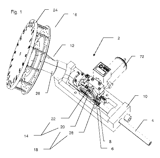
In Fig 1 the complete tool 2 is shown. A retractable cable 4 containing a
number of modules 6 is also shown. At two different positions in said
retractable cable, windows are made to access the modules, one at at least a
branch length downstream (not shown) and one, window 8, at the branch
location. A tapping box 10 is mounted around the retractable cable 4 at the
branch location, such that window 8 is placed inside said tapping box. In
tapping box 10 also a branch duct 12 is mounted. (see Fig 2) The tool 2 is
mounted on the tapping box 10. The tool consists of pull-out means 14, storing
means 16 and inserting means 18. The module 6 is pulled out by the drive
wheel 20 and upper press wheel 22. Storing is done in the container 24 that is
connected by funnel 26. Inserting is done by the same drive wheel 20 and the
lower press wheel 28.
In Fig 2 a first step of mounting the tool is shown. Before mounting the
entire tool, first the bottom part 30 is placed in tapping box 10. Said bottom
part is placed under the branch duct 12 with an O-ring 32 already in place.
CA 02781201 2012-05-17
WO 2011/061040 PCT/EP2010/066001
In Fig 3 the bottom part 30 of the tool is shown in more detail, without
tapping box 10, retractable cable 4 and branch duct 12. Bottom part 30
consists of a lower press wheel 28 that is spring (not shown) loaded via
5 holding block 34 against drive wheel 20 (not shown, is part of upper part,
see
Fig 5). The spring load can be adjusted by bolt 36 (not visible). With bolt 38
the lower press wheel can be released from the drive wheel. The module is
first guided (to the right axial position of the lower drive wheel) by a slit
40 in
guiding block 42. Immediately after the module has passed the lower press
wheel 28 and the drive wheel said module is guided through a channel 44,
formed by a slit 45 in block 46. The "ceiling" of channel 44 is formed by
block
48, which is a part of the upper part 50 of the tool (not shown in Fig 3). In
block 46 also the branch duct can be clamped, by teethed portion 52, and
sealed, by 0-ring 32 that is placed in groove 54 of block 46. Another channel
56 is made in block 46. Here a previously installed module can be placed.
With pins 58 the upper part is positioned on the lower part of the tool.
In Fig 4 a previously installed module 60 is shown, now with retractable
cable 4 and branch duct 12 shown again.
In Fig 5 the upper part 50 of the tool has been placed. Here block 48
can be recognized that matches with block 46. Upper part 50 also contains
drive wheel 20, mounted in holding block 62, and upper press wheel 22,
mounted in holding block 64. The upper press wheel is also spring (not
shown) loaded. The spring can be adjusted by bolt 66 and with bolt 68 the
upper press wheel can be released from the drive wheel. A motor can be
connected to axes 70 of the drive wheel. In this embodiment a magnetic clutch
72 (see Figure 1) is used onto which a cordless screwdriver/boring tool (not
shown) can be connected, optionally via a flexible shaft (also not shown).
Onto
block 48 is also mounted a clamping device 74 that holds the funnel 26 of the
storing means 16 (not represented here). Connected to holding block 64 is, via
crank 76, a spherical ball body 78. The space between the bottom of spherical
CA 02781201 2012-05-17
WO 2011/061040 PCT/EP2010/066001
6
ball body 78 and the inside of funnel 26 is just enough to let module 6 pass.
When module 6 is entirely pulled out of retractable cable 4 and leaves the
space between the drive wheel and the upper press wheel, the latter moves
down a little, activated by the spring load. Body 78 moves down with the upper
press wheel such that the space between the bottom of body 78 and the
inside of funnel 26 becomes less than the diameter of module 6, resulting in
holding module 6, preventing said module from being lost in the container 24.
The figure shows 5 an example of assembly portion comprising the
bottom part 30 and the upper part 50 of the tool 2 on which are fixed the
retracting means 20, 22, the storing means 26 and the inserting means 20,28.
The tool can be driven e.g. by its own motor and control or by a
cordless screwdriver/boring tool, optionally connected by a flexible shaft
connected to axes 70.
The force in pulling must be high (typically 10-25 N, preferably 15 N) to
obtain long enough pulling lengths. For this just gripping the module between
2 wheels is not sufficient. For this reason pulling out is done either by
using
caterpillars or, more simple (preferred), by using a capstan. In the latter
case
the drive wheel can serve as a capstan, see further.
The pushing force must be much lower than the pulling force (typically
2-5 N, preferably 3 N). For this reason a magnetic clutch is used. Also the
module must be guided through narrow channels after pushing, to prevent
kinking of the module. For longer length, assistance of a high-speed airflow
is
used. In US 20090236575 a tool has been described that uses such a
magnetic clutch, has the possibility of air-assistance and is provided with
anti-
buckling guide channels. In such a device the required pushing force of up to
5 N can easily be reached without using a capstan. In a preferred embodiment
the drive wheel direction in the pushing mode is opposite of that in the
pulling
mode, allowing simple and fool-proof switching between the different required
forces. It is possible to use a magnetic clutch in the push direction and none
in
CA 02781201 2012-05-17
WO 2011/061040 PCT/EP2010/066001
7
the pull direction. It is also possible to use clutches of different
(preferably
fixed) values in both directions. In case the motor has its own motor and
control the latter can take care of the different forces in both directions.
Fig 6 shows starting of the actual retraction process of the second
module 80. First a loop 82 of module 80 is taken out of the window 8 in
retractable cable 4, e.g. by using tweezers. Next said module is wound around
drive wheel 20, guided under upper press wheel 22 and said loop inserted into
the entrance of funnel 26 (shown transparently, for clarity; also not all
parts
shown). Note the 1800 capstan around the drive wheel 20. This results in extra
pulling force. If the pulling force at the location between drive wheel 20 and
upper press wheel 22 is F1, then the pulling force F2 (at window 8) is given
by
(see W. Griffloen, "Installation of optical cables in ducts", Plumettaz, Bex,
Switzerland, 1993):
Fz =F =exp(fir)
Here f is the coefficient of friction between module 80 and drive wheel
20. The ratio F2 / F, is given below for a number of coefficients of frictions
f:
f 0.1 0.2 0.5 1
F2 / F1 1.4 1.9 4.8 23.1
The coefficient of friction between module 80 and drive wheel 20 may
vary between 0.1 for lubricated plastic modules around steel drive wheels
until
more than 1 for non-lubricated plastic modules around rubber drive wheels.
For a preferred embodiment with slightly lubricated (to enhance pulling out of
the module out of the retractable cable) plastic modules around e.g. Linatex
or Nyoprene rubber drive wheels the coefficient is around 0.5. In this case
already around a factor of 5 more pulling force can be obtained than just by
pressing the upper press wheel 22 onto drive wheel 20. The invention is not
limited to these materials, nor to a capstan of 180 .
CA 02781201 2012-05-17
WO 20111061040 PCTIEP2010/066001
8
In order to keep the module 80 around drive wheel 20 the latter has
been accommodated with a U-groove 84, matching with a convex edge 86 of
upper press wheel 22. The static part 88 of module 80 is parked "behind" the
wheels 20 and 22. The loop 82 of module 80 had passed the space between
funnel 26 and spherical ball body 78.
Fig 7 shows the end of the retraction process. Here the full length of the
retracted module 80 has been pulled out and stored in the container 24. When
the module is pulled away from drive wheel 20 and leaves the space between
said drive wheel and upper press wheel 22, the spring action of said press
wheel causes said press wheel to move down to said drive wheel. At the same
time the spherical ball body 78, this is in communication (via crank 76) with
upper press wheel 22, moves down. This action causes to brake module 80,
which is then clamped between the spherical ball body 78 and funnel 26 (for
this reason the spherical ball body 78 is preferably made out of rubber-like
material). This prevent module 80 from being shot (or falling) too far into
the
funnel, which would make the module 80 inaccessible for further processing.
Different devices for storing cables in containers are known. One
example is described in US 5699974. Here an optical fiber transmission line is
coiled in a "rosette shape" into a circular container, using a special
mechanism. In another example also coiling a cable in a circular basket is
done, by means of a spinning arm, as described in US 5911381. In the latter
example all elements, including the arm, are developed "dividable", i.e. such
that a midspan section of the cable can be stored and retrieved without
cutting
the cable (note that none of these storing devices get their cable fed
directly
from pulling out). In the preferred embodiment of the present invention the
use
of such a spinning arm is considered to be too complicated (also it is not
intended to make the "rosette shapes"). Therefore in the preferred
embodiment containers are used where the modules can be inserted and
retrieved without using spinning arms (however, embodiments with spinning
arm might be needed for some types of module, and are also described). For
CA 02781201 2012-05-17
WO 2011/061040 PCT/EP2010/066001
9
this a special geometry was needed for the container, deviating from the
geometry of known containers. Most characteristic (new) properties are the
small height of the container and the use of a small diameter funnel for
feeding
the container. The diameter of the container is typically between 100 and 500
times that of the module, more specific between 150 and 300 times. The
height of the container is typically between 10 and 60 times the diameter of
the module, more specific between 10 and 40 times and even more specific
between 10 and 20 times. The diameter of the funnel is typically between 10
and 40 mm, more specific between 10 and 20 mm. The length of the funnel is
typically minimum 40 mm. Furthermore the ceiling and/or bottom of the
container can be made conical (tapered). Finally also an easy to mount simple
passive spinner is described that does not contain an arm.
Next step is pushing the stored module 80 into branch duct 12. Fig 8
shows the process close to the end of pushing said module into said branch
duct. For clarity the tapping box is not shown, the funnel 26 is shown
transparently and some parts of the upper part 50 of the tool are shown
separately in Fig 9. Now module 80 has been guided over another,
neighboring (can be of different material, because no large pulling force
required here), part 90 of drive wheel 20. Actual pushing is done at the place
where the second lower press wheel 28 presses (again spring action not
shown) said module against drive wheel 20. Module 80 is guided through
channel 44. First the module passes a guiding block 42 with guiding slit 40,
which brings the module in the position of channel 44. Then, when the module
has passed the position where lower press wheel 28 presses against drive
wheel part 90, the guiding channel 44 is confined at the bottom by the slit 45
in
guiding block 46 (part of lower part 30 of the tool) and at the top by the
(smooth) part 90 of drive wheel 20, against which said guiding block makes a
close contact (small gap, just no friction). When the module continues, the
confinement of guiding channel 44 at the top is taken over by block 48, a part
of the upper part 50 of the tool (shown in Fig 9). Note that at the entrance
the
slits in guiding blocks 42 and 46 are made a little rounded in order for the
CA 02781201 2012-05-17
WO 2011/061040 PCT/EP2010/066001
module to find its way without being stuck when pushed through. In guiding
block 42 also the outside is rounded.
Further in the channel optionally a lipseal (also rounded entrance,
5 lipseal not shown) makes an airtight seal when the module 80 has passed.
From this moment on the channel can be pressurized with air, fed through
inlet 92 (see Fig 9). For this the upper and lower part of the guiding block
are
sealed airtight, e.g. by using O-rings (not shown, only the O-ring 32 that
seals
the branch duct 12 has been shown). A previously installed module 60 may
10 also be present. The latter module has been bypassed in the guiding block
46
through channel 56. The spherical ball body 78 also serves to untwist a
possible remaining torsion twist in the last section of the retracted loop 94
of
module 80.
Finally the entire length of module 80 has been retrieved from the
container. Fig 10 shows the module entirely pushed into the branch duct 12. It
then follows a close to a straight path 96 from retractable cable 4 to branch
duct 12. After completion of all the modules (more modules like module 60
could have been previously installed and parked) the parts of the retractable
tool can be removed.
Note that for indoor use a simpler tool can be made. Here the tapping
box may be fully dividable, including the branch duct ports. A lot of elements
can be taken out then. No guiding blocks 46 and 48 are needed. Instead lower
press wheel 28 and a simple holder for the branch duct (but, with blowing
facility!) are connected to the tool. It is intended to keep as many parts as
possible the same for both indoor and outdoor applications, and supply the
rest as adapters.
Sometimes, depending e.g. on the properties of the module, coiling of
the module in the container changes spinning direction. This might cause
tangling when uncoiling. In most cases this changing in direction can be
CA 02781201 2012-05-17
WO 20111061040 PCT/EP2010/066001
11
avoided when the module is held in a confined geometry when going from
funnel to container. This can be done e.g. by making a guiding slit at that
location, like in Fig 11 where in mounting block 98 a slit 100 has been cut.
The
holes 102 allow pins (not shown) to lock the module inside the slit once
placed.
A central hole is another solution. A solution without the need to cut the
module is found in using two circular plates, shown in Fig 12. Here two
circular
plates are placed rotatable inside the funnel, close to the container. The
first
plate 112 contains a slit 114, the second plate 116 a slit 118. When the slits
are in the same position the loop can pass. The slits become a centered hole
when rotating one of the plates, e.g. by 90 . The plates 112, 116 are
represented transparent in the figure.
If this does not work a passive rotation device can be used, in fact the
same principle as the spinning arm in US 5911381. Only now the device is
made simpler, see Fig 13A. A massive cylinder 200 contains a slit 202. At the
entrance this slit extends until the axis of the cylinder, allowing the module
to
enter in the centre. Moving forward (direction container) the slit becomes
less
deep until it forms a channel at the surface of the cylinder. This transition
is
shown in cross-sectional view in A-A direction at hatched section 204 in Fig
13B. When the channel is at the surface there is a transition from a straight
channel to a helical channel, see also projected channel 206 cross-sectional
view in B-B direction in Fig 13C. When the first part of the loop is obtained
it
can be inserted with one branch in the slit 202 and channel 206. Then the
cylinder and loop of module are sleeved by a pipe section 210 (section of the
funnel), the second branch of the loop placed in straight slit 208. When
placed
in the funnel cylinder 200 will rotate in pipe section 210, driven by the
module
that is inserted. In order to lock cylinder 200 in axial direction the
internal
diameter of the other sections of the funnel are a little less in diameter
than
that of pipe section 210. Uses of special materials, like Teflon, are
preferred to
obtain a low rotational friction. It is also preferred to center the module
when
CA 02781201 2012-05-17
WO 2011/061049 PCTIEP2010/066001
12
entering the rotating cylinder 200. This can be done by placing the rotation
device immediately after drive wheel 20 and upper press wheel 22 (when
possible) or by placing plates 112 and 116 from Fig 12 just before the
rotational device.
In Figure 14 the friction of the rotating device (cylinder 200 with slit 202
and helical section 206 of that slit) has been further diminished by putting
it on
ball bearings 212. Now there can be a small gap (just enough to not touch and
not have friction, but amply enough to avoid that module 80 can come in
between) between cylinder 200 and pipe section 210. In this embodiment the
ball bearings are placed on a tapered (conical) central bottom 214 of the
container 24. Also the top of the container can contain a tapered section 216.
Note that it shall be possible to remove funnel 26 with pipe section 210
(mounting means not shown) from the container with mounted cylinder 200, in
order to be able to pass the loop 82 of module 80.
In Figures 15A and 15B a variant of Figure 14 is shown in which
mounting is made easier. Here pipe section 210a does not contain a slit 208 to
let pass one part of the loop of module 82. Instead said part of the loop is
now
outside pipe section 210a. For this the outer diameter of pipe section 210a is
sufficiently smaller than the inner diameter of funnel part 26a, such than the
cylinder 200 with pipe section 210a runs free from said funnel part, also when
said part of the loop is in between them. When the other part of the loop of
module is inserted in slit 202 it can be locked in the centre of cylinder 200
by
rotating circular plate 220, which has the same function as indicated in
Figure
12. Next said part of the module is guided in helical part 206 of slit 202 and
locked by sliding pipe section 210a down (leaving a side-opening of helical
part 206 of slit 202).
Cylinder 200 with pipe section 210 rotates on ball-bearing 212 and may
also be mechanically driven (electronic- or air-motor, not shown in Figure)
with
a very small torque in the direction of pushing the module out of helical part
CA 02781201 2012-05-17
WO 2011/061040 PCT/EP2010/066001
13
206 of slit 202 into the container. This will keep the module coiling against
the
outer wall of the container, especially important when uncoiling, avoiding
"pulling small loops" when the module lacks stiffness. Ball-bearing 212 is
mounted on circular plate 222a, which is a part of the strip 222 that connects
to funnel 26a. This allows mounting the funnel with rotatable cylinder 200 on
the tool, leaving enough space to access and perform the handlings described
above. When done the container 224 is sliced onto the funnel 26a. Slit 226
allows to pass strip 222 and rotatable cylinder 200 (with other parts) when
doing so, and strip 222 becomes an integral part of the container. Note that
it
is useful to clip (not shown) loop 82 of the module onto the upper part of
strip
222, to avoid uncontrolled spinning of cylinder 200 by the mechanical drive at
the end of the uncoiling process. This clipping on shall be done in a way not
to
hinder coiling of the loops and with some rounding of guiding to avoid kinking
of the module when pulling the loop away.
In Figure 16 another variant is shown of the container and with a
spinning arm like used in US 5911381. Here an air motor is used to move the
spinning arm. In Figure 17 a detailed view of the spinning arm with air motor
is
shown. Besides the container and clamping device, also the housing of the
motor is taken away for clarity. The gear wheel shown on the axis catches the
air that comes through the air-connection at the bottom. Inside the housing of
the motor (hided in Figure 17) the air is directed to blow against this gear
wheel in tangential direction, and in a direction such that the spinning arm
"pushes" the module.
Pulling out (retracting) the module from the cable might be enhanced by
using air blowing (from the far end) or air suction (from the tool). In the
latter
case the tool must be made such that it encloses fully the window in the
cable,
and air suction channels and connections must be made in the housing of the
tool (not shown). When the retractable cable is built with separate loose
tubes
with modules the suction "mouth" is easily connected on said loose tubes. For
air blowing assistance (from any suitable far end where the modules are cut
and compressed air connected) a compressor or gas bottle with remote
CA 02781201 2012-05-17
WO 2011/061040 PCT/EP2010/066001
14
controlled valve might be used. To avoid uncontrolled blowing out of the
module the free capstan part of the drive wheel might be covered with a "lid",
with a gap small enough to avoid the module from popping out, and large
enough not to touch the drive wheel and allowing enough free space for the
module. In the latter case the process of blowing out is only done for the
length needed to branch. The module may then be cut again, leaving a
remaining "blow out length" of module in the cable.
The invention is not limited to the tool and cables as described here.
For example, instead of loose coiling the modules in a container also coiling
around a reel can be done, like is done with casting rods and described in
e.g.
US 2648505. In this case the type with a stationary non-rotary drum or spool
is
meant.