Note: Descriptions are shown in the official language in which they were submitted.
CA 02781242 2014-04-25
1
ORAL CLEANING SECTION
FIELD OF THE INVENTION
The present invention is concerned with an oral cleaning section and it is in
particular concerned
with an oral cleaning section that has a first carrier on which at least a
first cleaning element is
mounted and a second carrier on which at least a second cleaning element is
mounted.
BACKGROUND OF THE INVENTION
US 2008/0307591 Al discloses as an oral cleaning section a brush section for
use with an electric
toothbrush. The brush section has a brush head portion that supports a first
plurality of contact
elements and a movable contact element holder that supports a second plurality
of contact
elements. In some embodiments, multiple rows of the first plurality of contact
elements are
separated by a row or rows of the second plurality of contact elements.
Each of the support structures must have a width that allows mounting of the
contact elements
without breaking or unduly deforming the support structures, which does not
allow a high density
of contact elements perpendicular to the row direction, specifically when the
rows of contact
elements of the first and second plurality of contact elements are alternately
arranged.
SUMMARY OF THE INVENTION
In one aspect, provided is an oral cleaning section that enables a high
density of first and second
oral cleaning elements while allowing for a relative movement of the first and
second cleaning
elements relative to each other.
The oral cleaning section as proposed comprises a first carrier that has a
cleaning side on which at
least a first cleaning element is mounted and a second carrier having a
cleaning side on which at
least a second cleaning element is mounted. At least an aperture is provided
in the first carrier.
The second carrier is arranged underneath the first carrier with respect to
the cleaning side of the
first carrier (i.e. the first and the second carrier are arranged on top of
each other such that the
cleaning side of the first carrier defines the outmost lying side of the
arrangement that is intended
CA 02781242 2012-05-17
WO 2011/073911
PCT/1B2010/055817
2
for facing an oral site to be cleaned). Further, the cleaning side of the
second carrier laterally
extends beyond the aperture, i.e. the second carrier overlaps with the first
carrier at least in a
lateral direction, which is enabled as the carriers (not only their mounting
surfaces) are arranged
underneath each other. The second cleaning element extends through the
aperture. The first
carrier and the second carrier are arranged for relative movement to each
other. As the first
carrier and the second carrier are arranged on top of each other this allows
for overlap in the wall
thickness needed for mounting the first and the second cleaning elements on
the first and second
carrier, respectively. This leads to a higher cleaning element density in the
formed cleaning
element field as the first and second cleaning elements can be brought closer
together with the
proposed arrangement than in an arrangement as known from US 2008/0307591 Al.
The first
and/or the second cleaning element or cleaning elements may be realized by
bristlesor by bristle
tufts, but this shall not mean that it should be excluded that cleaning
elements can be realized as
e.g. soft elastomeric cleaning structures.
In an embodiment of the proposed oral cleaning section, the first carrier and
the second carrier
are movably coupled to each other, e.g. the second carrier can be supported by
the first carrier so
as to enable the relative movement in a low volume realization.
In another embodiment of the proposed oral cleaning section, the second
carrier is arranged for
an oscillatory wiping motion around a longitudinal axis that is essentially
parallel to a
longitudinal extension axis of the oral cleaning section. Thus, in operation,
when the oral
cleaning section extends into the oral cavity, the second cleaning element or
the second cleaning
elements perform an oscillatory wiping motion similar to the wiping motion a
user of a manual
toothbrush would utilize to clean the teeth, but in the proposed embodiment
the user does not
have to move the oral cleaning section actively.
In a further embodiment of the proposed oral cleaning section, the oral
cleaning section
comprises a coupling element for transferring motion induced by a drive to at
least one of the
first or second carrier.
In an even further embodiment of the proposed oral cleaning section, the first
carrier is arranged
to at least partially envelope the second carrier. The first carrier may be
designed to house the
second carrier in an internal cavity. In particular, the second carrier may
have a second side that
CA 02781242 2012-05-17
WO 2011/073911 PCT/1B2010/055817
3
is exposed at the back of the oral cleaning section such that it can be
brought into contact with
tissue present in the oral cavity. The second side may have a texture, i.e. a
roughness or
structures suitable for e.g. cleaning the tongue.
In this respect, according to an aspect of the invention, an oral cleaning
section has a mounting
structure and a second carrier having a cleaning side on which at least a
cleaning element is
mounted and a second side being opposite to the cleaning side, which second
side is exposed so
that it can be brought into contact with tissue present in an oral cavity,
e.g. a tongue, where the
second side may be textured.
In yet another embodiment of the proposed oral cleaning section, at least a
first row of first
cleaning elements is mounted on the first carrier and at least a second row of
second cleaning
elements is mounted on the second carrier, with the second row of second
cleaning elements
extending through the aperture. Several apertures may be formed in the first
carrier such that one
of the several second rows of second cleaning elements extend through each one
of the apertures
and several first rows of first cleaning elements may be mounted on the first
carrier such that the
first rows and the second rows are alternately arranged. In such an
embodiment, a high density of
cleaning elements in a direction perpendicular to the row extension direction
can be achieved.
In an embodiment of the proposed oral cleaning section, the distance between
an outer edge of
the first cleaning element and an outer edge of the second cleaning element is
less than 1.6 mm,
e.g. less than 1.4 mm or less than 1.2 mm and in particular the distance may
be around 1.0 mm.
This can only be achieved if the wall thickness required for mounting
overlaps, which is allowed
because of the stacked arrangement of the first and second carriers.
In another embodiment of the proposed oral cleaning section, a third carrier
concludes the oral
cleaning section at a distal end (where the distal end is the end that lies
away from a handle
section of the oral cleaning device in an attached state, i.e. the proximal
end of the cleaning
section is the end that is intended for coupling to the handle section), with
the third carrier being
fixedly connected with the second carrier. In such an arrangement, the third
carrier would
perform the same relative motion to the first carrier as the second carrier,
e.g. an oscillatory
wiping motion around a longitudinal axis. The specific arrangement of a
carrier arranged so as to
conclude the oral cleaning section can be considered as a novelty in itself
that is independent
CA 02781242 2012-05-17
WO 2011/073911 PCT/1B2010/055817
4
from the other features previously discussed. The respective carrier may in
particular be arranged
for an oscillatory wiping motion around a longitudinal axis that is parallel
to the longitudinal
extension axis of the oral cleaning section.
The oral cleaning section may be realized as a replacement brush-head for
detachable connection
to a handle section of a toothbrush, in particular an electric toothbrush.
The invention is further concerned with an oral cleaning device (such as an
electric toothbrush or
a manual toothbrush) in which an oral cleaning section as proposed is
utilized. In case the oral
cleaning device is realized as a manual toothbrush, the oral cleaning section
may be integral with
a handle of the manual toothbrush. The oral cleaning device may comprise a
handle section to
which the oral cleaning section is detachably attached. In a manual
toothbrush, provision may be
made for an actuator that can be used to move the second carrier.
BRIEF DESCRIPTION OF THE DRAWINGS
The invention will be further elucidated by a description of an exemplary
embodiment and with
reference to figures. In the figures
Fig. lA is a side view onto an oral cleaning section as proposed that
is realized as a
detachable brush head for an electric toothbrush;
Fig. 1B is a frontal view onto the cleaning side of the oral cleaning
section shown in Fig.
1A;
Fig. 2 is a longitudinal cross sectional cut through the oral cleaning
section shown in Fig.
1B along line A-A;
Fig. 3 is a frontal view onto the cleaning side of the head part of the
oral cleaning section
shown in Fig. 1B without mounted bristle tufts;
Fig. 4 is a longitudinal cross sectional cut through a front section
of the head part of the
oral cleaning section as shown in Fig. 3 along line B-B;
Fig. 5 is a staged cross sectional cut through the head part of the
oral cleaning section as
shown in Fig. 4 along line C-C; and
Fig. 6 is a perspective view onto an oral cleaning device realized as
an electric
toothbrush that comprises a detachable oral cleaning section as proposed.
CA 02781242 2012-05-17
WO 2011/073911
PCT/1B2010/055817
DETAILED DESCRIPTION OF THE INVENTION
Fig. lA is a side view onto an exemplary embodiment of an oral cleaning
section 10 as proposed.
In the shown embodiment, the oral cleaning section 10 is realized as a
detachable brush head for
detachable connection to a handle section of an oral cleaning device (in Fig.
6 an exemplary oral
5 cleaning device is shown that is realized as an electric toothbrush). The
oral cleaning section 10
comprises a head part 100 and a tubular mounting structure 190. The head part
100 of the oral
cleaning section 10 comprises a cleaning element field 101 (here realized as a
bristle tuft field)
that extends from the head part 100 essentially into a direction perpendicular
to the longitudinal
extension direction L of the oral cleaning section, as is usual in the art to
enable effective
cleaning of an area in the oral cavity such as the teeth, the gums, the
mucosa, or the tongue
surface. In another embodiment, the oral cleaning section is integral with a
handle section of an
(battery-operated or rechargeable) electric toothbrush or a manual toothbrush.
The mounting structure 190 comprises a tube 191 that is slightly tapered
towards the head part
100 and is realized as being integral with a first carrier 110 of the head
part 100 of the oral
cleaning section 10. The tube 191 has an opening 192 at the end distal to the
head part 100 for
accommodating e.g. a driving shaft extending from the handle section of the
oral cleaning device
and for detachably mounting the oral cleaning section to a handle section of
an oral cleaning
device.
The first carrier 110 has a cleaning side 113 on which first cleaning elements
111 (here realized
as bristle tufts) are mounted, which first cleaning elements 111 are part of
the cleaning element
field 101. The first carrier 110 is an integral part of the oral cleaning
section 10 and can be
manufactured e.g. by a single plastic injection moulding process together with
the tube 191. The
first cleaning elements 111 may be considered as static cleaning elements of
the oral cleaning
section 10 as they are fixed in relation to the mounting structure 190. When
mounted onto the
handle section of the oral cleaning device, the first carrier 110 may not be
driven during
operation but may remain static with respect to the tube 191 and the handle
section. In another
embodiment, the whole cleaning section 10 is additionally driven into a motion
(e.g. a
reciprocation oscillation in longitudinal extension direction L). The first
cleaning elements 111
are then still fixed (i.e. static) with respect to the mounting structure 190.
CA 02781242 2012-05-17
WO 2011/073911 PCT/1B2010/055817
6
The head part 100 further comprises a second carrier 120 that is a movably
supported part of the
oral cleaning section 10 (as will be further discussed with reference to Fig.
2 and Fig. 4). Second
cleaning elements 121 (here also realized as bristle tufts) are mounted on the
cleaning side of the
second carrier 120, which second cleaning elements 121 extend through
apertures 130 formed in
the first carrier 110 so that the second cleaning elements 121 are here also
part of the cleaning
element field 101 and are arranged in close vicinity to the first cleaning
elements 111. The first
and second cleaning elements 111 and 121 form the cleaning element field 101
(here a bristle tuft
field) as is known from brush heads of manual or electric toothbrushes. When
attached to a
handle section of an electric oral cleaning device, the second carrier 120 may
be coupled to the
drive shaft of the electric oral cleaning device. During operation the second
carrier 120 would
then be set into an arcuate oscillatory motion (or: oscillatory wiping motion
or sweeping motion)
around a longitudinal axis that is essentially parallel to a longitudinal
extension axis L of the oral
cleaning section 10. In operation, the second cleaning elements 121 will then
move relative to the
first cleaning elements 111 (which will here remain static with respect to the
mounting structure
190). Generally, the first carrier 110 and the second carrier 120 are arranged
for relative
movement to each other, hence in another embodiment, the first carrier and the
second carrier are
both arranged for relative movement with respect to each other and with
respect to the mounting
structure. The oscillatory wiping motion of the second cleaning elements 121
around the
longitudinal axis is very similar to the motion a user would perform with a
manual oral cleaning
device, e.g. a manual toothbrush. Hence, the shown embodiment of an oral
cleaning section 10 as
proposed supports the feeling of a natural motion that may be preferred by
some users in contrast
to other motions the brush head may perform.
The second carrier 120 has a second side 124 that extends through an opening
in the backside of
the head part 100 (i.e. the first carrier is designed in such a way that it
covers the cleaning side of
the second carrier 120 and also partially envelopes the second carrier 120 ¨
one may say that the
second carrier 120 is here partially housed in the first carrier 110 ¨ such
that the second side 124
of the second carrier 120 is exposed). Hence, in operation not only the second
cleaning elements
121 move with respect to the mounting structure 191, also the second side 124
of the second
carrier 120 moves and thus provides a moving surface on the back side of the
head part 100. This
can be used to e.g. provide a tongue cleaner structure suitable to clean the
tongue by making the
second side 124 of the second carrier 120 textured (e.g. by making the second
side 124 rough or
CA 02781242 2012-05-17
WO 2011/073911 PCT/1B2010/055817
7
by providing structures on the backside; the texture may be provide by a
further material layer,
e.g. an elastomeric material, applied to the second side 124).
It is to be noted here that it is considered an invention in itself to provide
an oral cleaning section
having a head part and at least a carrier movably supported at the head part,
which movable
carrier has a first side on which cleaning elements are mounted and a second
side that is exposed
at the back side of the head part, which back side is opposite to the front
side of the head part
from which the cleaning elements are extending.
In the shown exemplary embodiment, the head part 100 further comprises a third
carrier 150
concluding the distal end of the oral cleaning section 10. The third carrier
150 has a cleaning side
on which third cleaning elements 151 (here again realized as bristle tufts)
are mounted. The
extension direction of the third cleaning elements 151 is somewhat (outwards)
inclined with
respect to the cleaning side of the oral cleaning section 10, whereas the
extension direction of the
first and second cleaning elements 111 and 121 is essentially normal to the
cleaning side of the
oral cleaning section 10. In the shown embodiment, the third carrier 150 is
integral with the
second carrier 120. The provision of such a movable carrier that concludes the
distal end of the
oral cleaning section and also performs an oscillatory wiping motion around a
longitudinal axis
that is essentially parallel to the longitudinal extension axis of the oral
cleaning section 10 is an
independent novelty in itself and is further considered as an optional feature
in the context of the
present invention.
In case the first or second or third cleaning elements 111, 121, or 151,
respectively, are realized
as bristle tufts, they can be mounted to the first, second, or third carriers
110, 120, or 150,
respectively, in a manner as is known in the art, e.g. via stapling
(anchoring), anchor free tufting
(AFT), or an in-moulding process. Instead of bristle or bristle tufts, at
least some of the cleaning
elements could e.g. be realized as soft and flexible elastomeric fingers for
massaging and softly
removing debris from oral tissue or as thin and flexible flaps for cleaning in
the interdental
cavities etc.
Fig. 1B is a frontal view onto the cleaning side 113 of the oral cleaning
section 10 as shown in
Fig. 1A. The same features as already shown in Fig. 1 A have the same
reference numerals and
reference is made to the description above. In the frontal view it can be seen
that the first
CA 02781242 2012-05-17
WO 2011/073911 PCT/1B2010/055817
8
cleaning elements 111 and the second cleaning elements 121 are arranged in
alternating rows.
The first cleaning elements 111 form first rows 112 of first cleaning elements
and the second
cleaning elements 121 form second rows 122 of second cleaning elements. Here,
three first rows
112, each having three double tufts, and three second rows 122, each having
two double tufts, are
alternately arranged in longitudinal direction. As shown here, the rows of
cleaning elements may
be centrically aligned in their rest position. Hence, during operation every
other row of cleaning
elements is set into an arcuate oscillation that occurs in a plane being
essentially perpendicular to
the longitudinal extension axis of the oral cleaning section 10. The second
cleaning elements 121
extend through apertures 130 formed in the first carrier 110. The apertures
130 have a
circumferential extension (here circumferential is meant with respect to the
longitudinal
extension axis L indicated by the dash-dotted line drawn in Fig. 1B; the
aperture 130 needs not to
be bent around the longitudinal extension axis) that is large enough to allow
for the arcuate
oscillation of the second cleaning elements 121, but the axial extension (in
the longitudinal
extension axis L) is only about as wide as the axial extension (here the axial
extension is the
width of the second cleaning elements 121 in the longitudinal extension
direction) of the second
cleaning elements 121 (here realized as bristle tufts) to allow for a high
density of the cleaning
elements in longitudinal direction (in other words: the chosen design supports
achieving a
minimal distance between the first and second rows 112 and 122 in the
longitudinal direction,
which leads to a high density of cleaning elements in longitudinal direction;
this will be further
discussed with reference to Fig. 3 and Fig. 4). The achieved density of
cleaning elements in
longitudinal direction is higher than the density that could be achieved on
first and second
carriers that are arranged side by side instead of on top of each other, as
the mounting of cleaning
elements such as bristle tufts requires a certain wall thickness of carrier
material between
mounting cavities to avoid that the material breaks (or deforms) during the
mounting process
(e.g. anchoring requires to have a wall thickness of about 0.8 mm or more).
The present invention
proposes to have a first and a second carrier 110 and 120 that are arranged on
top of each other
with respect to the extension direction of the cleaning elements such that the
first and second
carriers can move relatively to each other and can both laterally extend so
that they overlap in at
least a lateral direction. This allows for an overlap of the required walls
between the mounting
cavities so that in total a higher density of cleaning elements in
longitudinal direction is achieved
than with a side-by-side (non-overlapping) arrangement.
CA 02781242 2012-05-17
9
It is to be noted that the shown embodiment is just exemplary. The basic
feature relating
to an aspect of the proposed oral cleaning section relies in the fact that a
first carrier and a
second carrier are arranged on top of each other (the first and second
carriers thereby
laterally overlapping). Only a single second cleaning element may be mounted
on the
cleaning side of the second carrier. The first and/or second cleaning elements
may be
arranged as individual elements, in rows, in arrays etc. The first and second
cleaning
elements may be arranged in alternating order or the second cleaning element
or second
cleaning elements may extend through a single aperture formed in the first
carrier or
through several apertures formed in the first carrier.
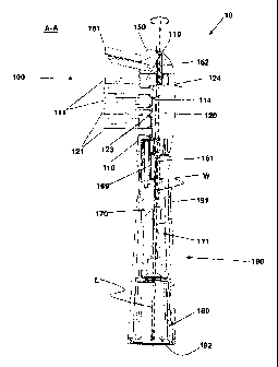
Fig. 2 is a longitudinal cross sectional cut through the oral cleaning section
10 as shown
in Fig. IB along line A-A. The tube 191 of the mounting structure 190 is
essentially
hollow and accommodates a sleeve 180 for clamping the oral cleaning section 10
onto a
mount of a handle section of an oral cleaning device and a coupling element
170 for
coupling the drive shaft of the oral cleaning device to the movably supported
second
carrier 120. The mount and the shaft of the handle section of the oral
cleaning device are
inserted into the hollow tube 191 through opening 192. The coupling element
170
comprises a snap-fit hook 171 having a V-like nose that snaps into a V-like
groove
formed in the shaft of the drive shaft to establish a detachable connection of
the coupling
element 170 and the shaft. Such a snap-hook fit is described in EP 0 500 537
Bl. The
sleeve 180 has a spring-like element that clamps onto the mount. The details
of the sleeve
180 and of the coupling insert 170 are in more detail explained in US
6,588,042 and EP 1
023 001 Bl. The coupling element 170 is coupled to the second carrier 120 via
a coupling
shaft 163, which coupling shaft 163 transfers a motion induced through the
drive shaft of
the oral cleaning device onto the coupling element 170 to the second carrier
120, so that
an oscillatory wiping motion of the second carrier 120 essentially around a
longitudinal
axis W defined by the first and second bearing shafts 161 and 162 is effected
during
operation. The longitudinal axis W defined by the first and second bearing
shafts 161 and
162 is essentially parallel to the longitudinal extension axis L of the oral
cleaning section
10. In the shown exemplary embodiment, the second carrier 120 is integral with
the third
carrier 150, which third carrier 150 is hence also performing said oscillatory
wiping
motion during operation. The third carrier 150 is movably supported at the
first carrier
110 via the second bearing shaft 162. As has already been explained, the
second cleaning
elements 121 that are mounted on the cleaning side 123 of the second carrier
120 extend
through apertures 130 formed in the first carrier 110 and thus form a high
density
cleaning element field together with the first cleaning elements 111 mounted
on the
CA 02781242 2012-05-17
cleaning side 113 (see Fig. 1 A) of the first carrier 110 in close vicinity of
the apertures
130. In the shown example, also the third cleaning elements 151 mounted on the
cleaning
side of the third carrier 150 are members of the cleaning elements field.
In Fig. 2 it can be seen that the second carrier 120 is arranged underneath
the first carrier
110, i.e. the cleaning side 123 of the second carrier 120 is positioned
underneath the
second side 114 (being opposite to the cleaning side of the first carrier) of
the first carrier
110, thus allowing for a lateral overlap of the first and second carriers 110
and 120.
Fig. 3 is a frontal view onto the cleaning side 113 of a "naked" head part
100' of the oral
care section as was shown in Fig. IB, but here shown without mounted cleaning
elements.
Thus, first mounting holes 119 for mounting of the first cleaning elements are
visible in
the first carrier 110, second mounting holes 129 for mounting the second
cleaning
elements are visible in the second carrier 120 through the apertures 130
formed in the first
carrier 110, and third mounting holes 159 for mounting of the third cleaning
elements are
visible in the third carrier 150. The first mounting holes 119 and the second
mounting
holes 129 are realized as double tuft holes with a recessed bridge wall to
enhance the
density of cleaning elements in the row direction. Mounting holes subdivided
into
multiple segments are described in EP 1 138 222 Bl. The vertical distance dl
(which is the
distance between the mounting holes measured in a plane perpendicular to the
longitudinal extension axis that coincides with line B-B) between the double
holes is here
about 0.8 mm, which is required to ensure e.g. secure stapling of bristle
tufts without the
risk to break or strongly deform the intermediate walls. The total
longitudinal distance d
between the rows of cleaning elements is here about 1 mm due to a wall
thickness of
about 0.8 mm between the first mounting holes 119 and the wall of the
apertures 130 and
a small distance of about 0.2 mm between the second mounting holes 129 and the
aperture walls (the latter distance allowing for a slight widening of e.g.
bristle tufts that
extend through the apertures 130). In case the second carrier 120 would be
arranged side-
by-side with the first carrier 110 (whether the carriers would be arranged at
the same
height or one of the carriers being somewhat recessed), the minimal wall
thickness of
about 0.8 mm required for the second carrier would add to the wall thickness
of 0.8 mm
required for the first carrier, so that a distance of at least about 1.6 mm
would result
between the rows of cleaning elements. A side-by-side arrangement of a first
carrier and a
second carrier is described in EP 2 107 892 Al. Hence, the proposed
arrangement of
second carrier 120 arranged underneath the first carrier 110 allows to
increase the density
of cleaning elements in the direction that is perpendicular to the row
direction. The
CA 02781242 2012-05-17
11
distance d between a row of first cleaning elements and a row of second
cleaning
elements can hence be made less than about 1.6 mm, the distance d can be made
less than
about 1.4 mm, less than about 1.2 mm and the distance d can be made to lie in
the range
of about 0.8 -1.0 mm. In general, the distance between cleaning elements
arranged on the
first carrier and cleaning elements arranged on the second carrier can be made
about as
small as the distance between two cleaning elements arranged on only one of
the two
carriers due to the allowed lateral overlap between the first and second
carriers arranged
on top of each other.
Fig. 4 is a longitudinal cross sectional cut through a front section of the
"naked" head part
100' as shown in Fig. 3 along the line B-B as indicated in Fig. 3. The second
carrier 120 is
movably supported at the first carrier 110 of the oral cleaning section via
the first bearing
shaft 161 and the second bearing shaft 162. The front part of the first
bearing shaft 161 is
secured to the second carrier 120. The second bearing shaft 162 extends in
longitudinal
direction and is secured to the third carrier 150 and is loosely extending
into a bore
formed in the first carrier 110 so that the second carrier 120 (and the third
carrier 150
being integral with the second carrier 120) can pivot around the longitudinal
axis W
defined by the first bearing shaft 161 and the second bearing shaft 162. As
the cross
sectional cut goes through the walls between the second mounting holes, the
second
mounting holes are not visible. The cut goes also through the recessed bridge
walls of the
first mounting holes so that the first mounting holes are also not visible. A
third mounting
hole 159 is visible in this cross-sectional cut. Further, the apertures 130
are visible. In the
mounted state, the second cleaning elements 121 extend through the apertures
130 as is
shown in Fig. 2. The second carrier 120 has a second side 124 that is exposed
at the back
side of the head part. The second side 124 may be textured, e.g. may be
provided with a
pattern of elastomeric elements suitable for tongue cleaning as is generally
known in the
art. As can be seen, the cleaning side 123 of the second carrier 120 laterally
extends (here:
in longitudinal direction) underneath the second side 114 of the first carrier
110 so that
the first and second carriers 110 and 120 overlap in longitudinal direction.
Fig. 5 is a stepped cross sectional cut through the head part of the oral
cleaning section
along line C-C as indicated in Fig. 4. Line C-C is stepped so that the cut
goes through the
first mounting
CA 02781242 2012-05-17
WO 2011/073911 PCT/1B2010/055817
12
holes 119 and the second mounting holes 129. The second carrier 120 is
partially enveloped (i.e.
enclosed) by the first carrier 110. The second side 124 of the second carrier
120 is exposed at the
back side of the head part so that it can be brought into contact with tissue
present in the oral
cavity, e.g. the tongue. In another embodiment, the first carrier is fully
enveloping the second
carrier (i.e. the second carrier is fully housed inside the first carrier
without the second side of the
second carrier being exposed).
Fig. 6 shows an oral cleaning device 1 realized as an electric toothbrush
comprising a handle
section 20 and an oral cleaning section 10 as proposed realized as a
detachable brush head.
The dimensions and values disclosed herein are not to be understood as being
strictly limited to
the exact numerical values recited. Instead, unless otherwise specified, each
such dimension is
intended to mean both the recited value and a functionally equivalent range
surrounding that
value. For example, a dimension disclosed as "40 mm" is intended to mean
"about 40 mm."