Note: Descriptions are shown in the official language in which they were submitted.
CA 02781279 2012-05-17
WO 2011/063062 PCT/US2010/057128
1
BELT HAVING SEMICONTINIJOIJS PATTERNS AND NODES
FIELD OF THE INVENTION
The present invention relates to belts used for making cellulosic fibrous
structures, such
as paper towel or toilet tissue products. Particularly this invention relates
to a belt used in a
through-air drying process for making cellulosic fibrous structures, and more
particularly to a
belt having a particular pattern thereon which imparts properties to the paper
in a like pattern.
BACKGROIJND OF THE INVENTION
Cellulosic fibrous structures, such as paper, are well known in the art. For
example,
cellulosic fibrous structures are a staple of every day life and are found in
facial tissues, toilet
tissue, and paper toweling.
Specifically a secondary belt used in the wet end of the papermaking process
can affect
the properties imparted to the cellulosic fibrous structure such as caliper
and CD strctch.
Controlling, maximizing, and maintaining CD stretch properties and caliper
properties, that is
generated in the wet end of papermaking, throughout the dry end processing of
paper webs such
as converting, is often challenging. In addition these secondary belts also
need to be durable and
designed such that they withstand high temperature and pressure during the
manufacturing of
cellulosic fibrous structures. Otherwise these belt need to be replaced or
repaired frequently, thus
driving up manufacturing costs.
Accordingly, a need exists to provide greater control over the caliper and CD
stretch, of
the cellulosic fibrous structure, while also maximizing the belt life in the
papermaking process.
SUMMARY OF THE INVENTION
'Ibe inventions relates to a macroscopically monoplanar secondary belt for
manufacturing
a cellulosic fibrous structure, and having two mutually orthogonal principal
directions, a machine
direction and a cross machine direction, the belt comprising:
a reinforcing structure; and
a framework of protuberances joined to said reinforcing structure and
extending
outwardly therefrom to define deflection conduits between the protuberances,
the
framework of protuberances comprising a semicontinuous pattern and the
deflection
conduits comprising a semicontinuous pattern, the protuberances and the
deflection
CA 02781279 2012-05-17
WO 2011/063062 PCT/US2010/057128
2
conduits having a vector component extending substantially throughout one
principal
direction of the belt, each protuberance of the pattern being spaced apart
from an adjacent
protuberance in the pattern;
the protuberances comprising primary protuberances having a first width, T,
and nodes
having a second width, N, wherein a ratio of N to T is from about 1.5 to about
5.
BRIEF DESCRIPTION OF THE DRAWINGS
While the specification concludes with claims particularly pointing out and
distinctly
claiming the present invention, it is believed the invention will be better
understood by the
following specification taken in conjunction with the associated drawings in
which like
components are given the same reference numeral, and:
FIG. 1 is a top plan view of a secondary belt according to the present
invention having a
reinforcing structure and a framework of protuberances having deflection
conduits therebetween;
FIG. 2 is a diagonal sectional view taken along lines 2--2 of FIG. 1;
FIG. 3 is a top plan view of the framework of protuberances of the secondary
belt
according to Figure 1; and
FIG. 4 is a top plan view of an alternative embodiment of a framework of
protuberances
for use with the reinforcing structure of the secondary belt according to
Figure 1.
DETAILED DESCRIPTION OF THE INVENTION
Definitions
As used herein, a "secondary belt" or "belt" refers to an apparatus or a belt,
respectively,
having an embryonic web contacting surface and which is used to carry or
otherwise process an
embryonic web of cellulosic fibers after initial formation in the wet end of
the papermaking
machinery. A secondary belt may include, without limitation, a belt used for
molding an
embryonic web of the cellulosic fibrous structure, a through-air drying belt,
a belt used to transfer
the embryonic web to another component in the papernmking machinery, or a
backing wire used
in the wet end of the papermaking machinery (such as a twin-wire former) for
purposes other
than initial formation. A belt according to the present invention does not
include embossing rolls,
which deform dry fibers after fiber-to-fiber bonding has taken place. Of
course, a cellulosic
fibrous structure according to the present invention may be later embossed, or
may remain
unembossed.
CA 02781279 2012-05-17
WO 2011/063062 PCT/US2010/057128
3
"Basis Weight", as used herein, is the weight per unit area of a sample of
fibrous structure
reported in lbs/3000 ft2 or g/m2.
"Fiber- as used herein means an elongate particulate having an apparent length
greatly
exceeding its apparent diameter, i.e. a length to diameter ratio of at least
about 10. Fibers having
a non-circular cross-section are common; the "diameter" in this case may be
considered to be the
diameter of a circle having cross-sectional area equal to the cross-sectional
area of the fiber.
More specifically, as used herein, "fiber" refers to fibrous structure-making
fibers. The present
invention contemplates the use of a variety of fibrous structure-making
fibers, such as, for
example, natural fibers, including wood fibers, or synthetic fibers made from
natural polymers
and/or synthetic fibers, or any other suitable fibers, and any combination
thereof.
"Fibrous structure" as used herein means a structure (web) that comprises one
or more
fibers. Nonlimiting examples of processes for making fibrous structures
include known wet-laid
fibrous structure making processes, co-forming fibrous structure making
processes, etc. Such
processes typically include steps of preparing a fiber composition, oftentimes
referred to as a
fiber slurry in wet-laid processes, either wet or dry, and then depositing a
plurality of fibers onto
a forming wire or belt such that an embryonic fibrous structure= is formed,
drying and/or bonding
the fibers together such that a fibrous structure is formed, and/or further
processing the fibrous
structure such that a finished fibrous structure is formed. The fibrous
structure may be a through-
air-dried fibrous structure and/or conventionally dried fibrous structure. The
fibrous structure
may be creped or uncreped. The fibrous structure may exhibit differential
density regions. The
fibrous structure may be pattern densified. The fibrous structures may be
homogenous or
multilayered in construction.
After and/or concurrently with the forming of the fibrous structure, the
fibrous structure
may be subjected to physical transformation operations such as embossing,
calendaring, selling,
printing, folding, softening, ring-rolling, applying additives, such as latex,
lotion and softening
agents, combining with one or more other plies of fibrous structures, and the
like to produce a
finished fibrous structure product.
As used herein, "fibrous structure products" or "paper products" or "products"
mean
paper products comprising fibrous structure, usually cellulose fibers. In one
embodiment, the
products of the present invention include tissue-towel paper products,
including paper toweling,
facial tissue, bath tissue, table and/or napkins. The products of the present
invention may be in
any suitable form, such as in a roll, in individual sheets, in connected, but
perforated sheets, in a
folded format or even in an unfolded format.
CA 02781279 2012-05-17
WO 2011/063062 PCT/US2010/057128
4
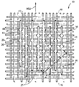
As shown in Figs. 1 and 2 the invention comprises a belt 10 for manufacturing
a
cellulosic fibrous structure. For example, the belt 10 embodiment of an
apparatus according to
the present invention comprises two primary elements: a patterned framework of
protuberances
20 and a reinforcing structure 30. The reinforcing structure 30 of the belt 10
has two opposed
major surfaces. One major surface is the paper contacting side 32 and from
which the
protuberances 20 extend. The other major surface of the reinforcing structure
30 of the belt 10 is
the backside 34, which contacts the machinery employed in a typical
papermaking operation.
Machinery employed in a typical papennaking operation include vacuum pickup
shoes, rollers,
etc., as are well known in the art and will not be further discussed herein.
Generally, for a belt 10 according to the present invention, the "machine
direction" of the
belt 10 is the direction within the plane of the belt 10 parallel to the
principal direction of travel
of the cellulosic fibrous structure during manufacture. The machine direction
is designated by
arrows "MD" in FIG. 1. The cross machine direction is generally orthogonal the
machine
direction and also lies within the plane of the belt 10. The Z-direction is
orthogonal both the
machine direction and cross machine direction and generally nonnal to the
plane of the belt 10 at
any position in the papermaldng process. The machine direction, cross machine
direction. and Z-
direction form a Cartesian coordinate system.
The belt 10 according to the present invention is essentially macro-scopically
monoplanar. As used herein a component is "macroscopically monoplanar" if such
component
has two very large dimensions in comparison to a relatively small third
dimension. The belt 10 is
essentially macroscopically monoplanar in recognition that deviations from
absolute planarity are
tolerable, but not preferred, so long as the deviations do not adversely
affect the performance of
the belt 10 in making cellulosic fibrous structures thereon.
In a belt 10 embodiment, the reinforcing structure 30 comprises a series of
filaments, in
one embodiment woven in a rectangular pattern to define interstices
therebetween. The
interstices allow fluids, such as drying air, to pass through the belt 10
according to the present
invention. In an embodiment the interstices form one of the groups of openings
in the belt 10
according to the present invention, which openings are smaller than those
defined by the
deflection conduits between the patterned framework of protuberances 20.
If desired, the reinforcing structure may have vertically stacked machine
direction
filaments to provide increased stability and load bearing capability. By
vertically stacking the
machine direction filaments of the reinforcing structure, the overall
durability and performance
of a belt 10 according to the present invention is enhanced.
CA 02781279 2012-05-17
WO 2011/063062 PCT/US2010/057128
The reinforcing structure 30 should not present significant obstruction to the
flow of
fluids, such as drying air therethrough and, therefore, should be permeable
(and may be highly
permeable). The permeability of the reinforcing structure 30 may be measured
by the airflow
therethrough at a differential pressure of about 1.3 centimeters of water (0.5
inches of water). In
5 an embodiment a reinforcing structure 30 having no framework of
protuberances 20 attached
thereto should have a permeability at this differential pressure of about 240
to about 490 standard
cubic meters per minute per square meter of belt 10 area (800 to 1,600
standard cubic feet per
minute per square foot). Of course, it will be apparent that the permeability
of the belt 10 will be
reduced when the framework of protuberances 20 is attached to the reinforcing
structure 30. In an
embodiment the belt 10 having a framework of protuberances 20 has an air
permeability of about
90 to 180 standard cubic meters per minute per square meter (300 to 600
standard cubic feet per
minute per square foot).
In an alternative embodiment, the reinforcing structure 30 of a belt 10
according to the
present invention may have a textured backside 34. The textured backside 34
has a surface
topography with asperities to prevent the buildup of papennaking fibers on the
backside 34 of the
belt 10, reduces the differential pressure across the belt 10 as vacuum is
applied thereto during
the papennaking process, and increases the rise time of the differential
pressure prior to the
maximum differential pressure occurring.
In an embodiment a reinforcing structure 30 or belt 10 for use with the
present invention
may be made in accordance with the teachings of commonly assigned U.S. Pat.
Nos. 5,098,522
issued Mar. 24, 1992 to Smurkoski, et al. 4,514,345; 5,073,235; 5,260,171;
5,629,052, 6,287,641;
5,962,860; 6,743,571.
The other primary component of the belt 10 according to the present invention
is the
patterned framework of protuberances 20. The protuberances 20 define
deflection conduits 40
therebetween. The deflection conduits 40 allow water to be removed from the
cellulosic fibrous
structure by the application of differential fluid pressure, by evaporative
mechanisms, or both
when drying air passes through the cellulosic fibrous structure while on the
belt 10 or a vacuum
is applied through the belt 10. The deflection conduits 40 allow the
cellulosic fibrous structure to
deflect in the Z-direction and generate the caliper of and aesthetic patterns
on the resulting
cellulosic fibrous structure.
In Figs. 1, 2 and 3, in an embodiment the protuberances 20 are arranged in a
semicontinuous pattern 25. One particular semicontinuous pattern 25 is shown
in Figs. 1, 2 and 3.
As used herein, a pattern of protuberances 20 is considered to be
"semicontinuous- if a plurality
CA 02781279 2012-05-17
WO 2011/063062 PCT/US2010/057128
6
of the protuberances 20 extends substantially throughout one dimension of the
apparatus, and
each protuberance 20 in the plurality is spaced apart from adjacent
protuberances 20.
In an embodiment the protuberances 20 have a vector component extending
substantially
throughout one principal direction of the belt 10, each protuberance of the
pattern being spaced
apart from an adjacent protuberance in the pattern. The protuberances comprise
a plurality of
primary protuberances 44 having a first width "T' and nodes 48 having a second
width "N". In
an embodiment the belt 10 may exhibit a ratio of N to T of from about 1.5 to
about 5. In another
embodiment the ratio of N 10 T is Irom about 2 to about 4 and/or from about 2
to about 3. In an
embodiment the plurality of primary protuberances have substantially
equivalent width.
All of the nodes of a belt may be substantially identical in surface area,
size and shape,
wherein the second width, N, of the nodes, may be the maximum width of the
node.
The belt may also have nodes comprising general plane geometry shapes selected
from
the group consisting of squares, circles, ellipses, ovals, rectangles,
triangles, pentagons,
hexagons, and combinations thereof. The belt may also comprise nodes comprise
non-plane
geometry shapes. For example, the non plane geometry shapes may be selected
from the group
consisting of stars, flowers, hearts, and combinations thereof. Belts having
nodes that are not
identical in surface area, size and shape, and have nodes of varied sizes and
shapes, the second
width, N, may be an average of the maximum width of each shape and size of
nodes present on
the belt.
The nodes may be arranged in any desired matrix. The nodes may be aligned in
either or
both the machine direction and/or cross machine direction. The nodes may be
staggered, for
example in a non-random pattern, in either the machine direction, the cross
machine direction, or,
alternatively, nodes may be bilaterally staggered. For the embodiments
described herein, node
frequency may be about 50 to about 200 per square inch and/or about 75 to
about 190 per square
inch and/or about 100 to about 180 per square inch.
The protuberances 20 in the semicontinuous pattern 25 may comprise a plurality
of
primary protuberances 44 and a plurality of nodes 48. Figs. 1 and 3 show a
belt 10 wherein the
primary protuberances 44 are spaced substantially equidistance frotn the
adjacent primary
protuberances 44. The primary protuberances 44 may be parallel to adjacent
primary
protuberances 44. The plurality of the primary protuberances comprising said
pattern may be
generally parallel to the principal direction of the belt. FIG. 3 is a top
plan view of the
framework of protuberances of the belt according to Figure 1.
CA 02781279 2012-05-17
WO 2011/063062 PCT/11S2010/057128
7
The primary protuberances 44 comprise a first width T of from about from about
5 mils
(0.005 inches) to about 40 mils (0.04 inches).
As shown in Figs 1 and 3 the primary protuberances 44 may be generally
parallel so as to
form a pattern in which the nodes 48 of adjacent protuberances 20 are offset
from one another
with respect to the phase of the pattern as illustrated. The protuberances 20
may be aligned in
any direction within the plane of the belt 10.
The protuberances 20 may span the entire cross machine direction of the belt
10, may
span the entire machine direction of the belt 10, or may run diagonally
relative to the machine
and cross machine directions of the belt. Of course, the direction of the
protuberance 20
alignment (machine direction, cross machine direction, and/or diagonal) refers
to the principal
alignment of the protuberances 20. Within each alignment, the protuberance 20
may have nodes
aligned at other directions, but aggregate to yield the particular alignment
of the entire
protuberance 20.
The framework of protuberances 20 arranged in a semicontinuous pattem 25 are
to be
distinguished from a pattern of discrete protuberances, in which any one
protuberance does not
extend substantially throughout a principal direction of the belt 10. An
example of discrete
protuberances is found at FIG. 4 of commonly assigned U.S. Pat. No. 4,514,345
issued Apr. 30,
1985 to Johnson, et al.
Similarly, a framework of protuberances 20 in a semicontinuous pattern 25 is
to be
distinguished from protuberances forming an essentially continuous pattern. An
essentially
continuous pattern extends substantially throughout both the machine direction
and cross
machine direction of the belt 10, although not necessarily in a straight line
fashion. Alternatively,
a pattern may be continuous because the framework forms at least one
essentially unbroken net-
like pattern. Examples of protuberances forming an essentially continuous
pattern are illustrated
by FIGS. 2-3 of the aforementioned U.S. Pat, No. 4,514,345 issued to Johnson,
et al or by the
aforementioned U.S. Pat. No. 4,528,239 issued to Trokhan.
As illustrated in FIG. 2, the framework of protuberances 20 in a
semicontinuous pattem
according to the present invention is joined to the reinforcing structure 30
and extends outwardly
from the paper contacting side 32 thereof in the Z-direction. The
protuberances 20 may have
straight sidewalls, tapered sidewalls, and be made of any material suitable to
withstand the
temperatures, pressures, and deformations which occur during the papermaking
process. In one
embodiment the protuberances 20 are made of photosensitive resins.
CA 02781279 2012-05-17
WO 2011/063062 PCT/IJS2010/057128
8
The photosensitive resin, or other material used to form the pattern of
protuberances 20,
may be applied and joined to the reinforcing structure 30 in any suitable
manner. In an
embodiment the manner of attachment and joining is applying liquid
photosensitive resin to
surround and envelop the reinforcing structure 30, cure the portions of the
liquid photosensitive
resin which are to form the semicontinuous pattern of the protuberances 20,
and wash away the
balance of the resin in an uncured state. Suitable processes for manufacturing
a belt 10 in
accordance with the present invention are disclosed in the aforementioned U.S.
Pat. No.
4,514,345 issued to Johnson, et al., commonly assigned U.S. Pat. No. 4,528,239
issued Jul. 9,
1985 to Trokhan, and the aforementioned U. 5. Pat. No. 5,098,522 issued to
Smurkoski, et al. As
indicated in these references, the framework of protuberances 20 may be
determined by
transparencies in a mask through which an activating wave length of light is
passed. The
activating light cures portions of the photosensitive resin opposite the
transparencies. Conversely,
the portions of the photosensitive resin opposite the opaque regions of the
mask are washed
away, leaving the paper contacting side 32 of the reinforcing surface exposed
in such areas.
Thus, to form an embodiment of a belt 10 according to the present invention,
the mask
may be formulated with transparent regions having a semicontinuous pattern 25
as described
herein. Such a mask will form a like pattern of protuberances 20 on the belt
10.
Fig. 4 shows a top plan view of an alternate embodiment a framework of
protuberances
58 arranged in a semicontinuous pattern 60 that may be used alternative
pattern in associated
with the reinforcing structure of Fig. 1. In an embodiment the protuberances
58 have a vector
component extending substantially throughout one principal direction of the
belt 10, each
protuberance of the pattern being spaced apart from an adjacent protuberance
in the pattern. The
protuberances comprise a plurality of primary protuberances 64 having a first
width "T" and
nodes 66 having a second width "N". In an embodiment the ratio of N 10 T of
from about 1.5 to
about 5 and/or the ratio of N to T is from about 2 to about 4 and/or from
about 2 to about 3. As
shown in Fig. 4, in an embodiment the plurality of primary protuberances 64
have substantially
equivalent width and all of the nodes 66 may be substantially identical in
surface area, size and
shape, wherein the second width, N, of the nodes, may be the maximum width of
the node.
The protuberances 58 in the semicontinuous pattern 60 may comprise a plurality
of
primary protuberances 64 and a plurality of nodes 66. Fig. 4 shows the primary
protuberances 64
are spaced substantially equidistance from the adjacent primary protuberances
64. The primary
protuberances 64 may be parallel to adjacent primary protuberances 64. The
plurality of the
primary protuberances 64 comprising said pattern may be generally parallel to
the principal
CA 02781279 2012-05-17
WO 2011/063062 PCT/US2010/057128
9
direction of the belt. The primary protuberances 64 comprise a first width T
of from about from
about 5 mils (0.005 inches) to about 40 mils (0.04 inches). As shown in Fig. 4
the primary
protuberances 64 may be generally parallel so as to form a pattern in which
the nodes 66 of
adjacent protuberances 58 are not offset from one another with respect to the
phase of the pattern
as illustrated. The protuberances 58 may be aligned in any direction within
the plane of the belt
10.
For example protuberances 20 forming a semicontinuous pattern may have
characteristics
which produce desired properties of the cellulosic fibrous structures. The
geometry of the
protuberances 20 may influences the properties of the resulting cellulosic
fibrous structure made
on the secondary belt 10. For example, the protuberances 20 may produce hinge
lines in the
cellulosic fibrous structure, which hinge lines impart softness or enhance the
appearance of
softness to the fibrous structure.
Furthermore, the semicontinuous pattern of protuberances 20 will yield a like
semicontinuous pattern of high and low density regions in the cellulosic
fibrous structure made
on this belt 10. Such a pattern in the resulting cellulosic fibrous structure
occurs for two reasons.
First, the regions of the cellulosic fibrous structure coincident the
semicontinuous deflection
conduits 40 will be de-densified by the air flow therethrough or will be de-
densified by the
application of a vacuum to the deflection conduits 40. In an embodiment, the
regions of the
cellulosic fibrous structure coincident the protuberances 20 will be densified
by the transfer of
the cellulosic fibrous structure to a rigid backing surface, such as a Yankee
drying drum.
In an embodiment the geometry of the protuberances 20 may be considered in a
single
direction, or may be considered in two dimensions, and may be considered as
either lying within
or normal to the plane of the secondary belt 10 according to the present
invention.
Particularly, the Z-direction extent of the protuberances 20 in a single
direction normal to
the plane of the belt 10 determines the height of the protuberances 20 above
the paper contacting
side 32 of the reinforcing structure 30. If the height of the protuberances 20
is too great,
pinholing and apparent transparencies or light transmission through the
cellulosic fibrous
structure will occur. Conversely, if the Z-direction dimension of the
protuberances 20 is smaller,
the resulting cellulosic fibrous structure will have less caliper. Pinholing
and low caliper are
undesirable because they present an apparently lower quality cellulosic
fibrous structure to the
consumer.
In an embodiment the protuberances 20 may have a height between about 0.05
millimeters and about 0.76 millimeters (0.002 and 0.030 inches), and/or
between about 0.13
CA 02781279 2012-05-17
WO 2011/063062 PCT/U S2010/057128
millimeters and about 0.66 millimeters (0.005 and 0.026 inches), and/or
between about 0.20
millimeters and about 0.56 millimeters (0.008 and 0.022 inches).
Referring again to FIGS. 1, 2 and 3 and continuing the single direction
analysis, the
spacing between inwardly facing edges 54 of adjacent protuberances 20 must be
considered both
5 in terms of the distance between the adjacent primary protuberances 44
and the distance between
the inwardly facing edges 54 of the nodes 48, for example on one protuberance,
and the inwardly
facing edges 54 on a primary protuberance 44 of another protuberance. If,
within limits, the
spacing is too great for a given Z-direction extent, pin-holing is more likely
to occur. Also, if the
spacing between the inwardly facing edges 54 of adjacent protuberances 20 is
too great, another
10 undesired resultant phenomenon may be that fibers will not span the
distal ends 50 of adjacent
protuberances 20, resulting in a cellulosic fibrous structure having lesser
strength than can be
obtained if individual fibers span adjacent protuberances 20. Conversely, if
the spacing between
the inwardly facing edges of adjacent protuberances 20 is too small, the
cellulosic fibers will
bridge adjacent protuberances 20, and in an extreme case little caliper
generation will result.
Therefore, the spacing between the inwardly facing edges 54 of adjacent
protuberances 20 must
be optimized to allow sufficient initial caliper generation to occur and to be
maintained
throughout the papermaking and converting process as well as to minimize pin-
holing.
In an embodiment and in Figs. 1 and 3 the protuberances 20 are not of constant
width.
The nodes 48 of adjacent protuberances 20 may comprise a staggered
configuration 28 so that the
inwardly facing edges 54 of the nodes 48 of the protuberances 20 are not
parallel to each other.
In Figs. 1 and 3 the inwardly facing edges of the primary protuberances 44,
however, are parallel
to each other. In an embodiment the minimum distance, B, between inwardly
facing edges 54 of
the protuberances 20, may occur at the inwardly facing edge 54 of a node 44
and the inwardly
facing edge 54 of an adjacent primary protuberance 44. In an embodiment B may
be from about
20 mils (0.02 inches) to about 80 mils (0.080inches) apart or about 22 mils
(0.022 inches) to
about 40 mils (0.04 inches) apart in a direction that is generally orthogonal
to such surfaces.
In an embodiment the maximum distance, A, between inwardly facing edges 54 of
the
protuberances 20, may occur at the inwardly facing edge 54 of a primary
protuberance 44 and the
inwardly facing edge of an adjacent primary protuberance 44. In an embodiment
A may be from
about 40 mils to about 100 mils apart (about 0.040 to about 0.1 inches) or
about 42 mils to about
80 mils apart (about 0.042 to about 0.08 inches) or about 45 mils to about 60
mils apart (about
0.044 to about 0.06 inches) in a direction that is generally orthogonal to
such surfaces. This
spacing will result in a cellulosic fibrous structure which generates maximum
and sustainable
CA 02781279 2012-05-17
WO 2011/063062 PCT/US2010/057128
11
caliper when made of conventional cellulosic fibers, such as Northern softwood
kraft or
eucalyptus.
A further single dimension analysis relates to the width across the distal end
50 of the
protuberance 20. The width across the distal end is measured generally normal
to the principal
dimension of the protuberance 20 within the plane of the belt 10 at a given
location. As has been
noted in the design of prior belts, if the protuberance 20 is not wide enough,
the protuberance 20
will not withstand the pressures and temperature differentials encountered
during and incidental
to the papennaking process. Accordingly, such a belt 10 will have a relatively
short life and have
to be frequently replaced. Moreover, if the protuberances 20 are too wide, a
more one-sided
texture will result. Through the addition of the node of a particular size or
surface area in
relation to the size or surface area of the primary protuberances, more
flexibility is achieved in
choosing a size and surface area of the primary protuberance. In addition
maximal belt life is
achieved over a broader range of protuberance sizes than may be achieved for
belt without the
inclusion of a plurality of nodes. In addition the selection of the node of a
particular size and
dimension achieves a more stable caliper in the fibrous structure product.
In an embodiment the inwardly facing edges 54 of the protuberances 20 may be
tapered
and the surface area of the distal ends 50 of the protuberances may be less
than the surface area
of the proximal ends 52 of the protuberances 20 and hence the surface area of
the proximal ends
52 of the protuberances 20 occupy a greater surface area than the distal ends
50.
In some embodiments the proximal ends 52 comprise a surface area, of all of
the
protuberances 20, from about 25 % to about 75 % of the belt 10 surface area,
and/or from about -
25% to about 50% of the belt surface area. In an embodiment the distal ends 50
comprise a
surface area, of all of the protuberances 20, from about 15% to about 65 %
and/or from about
20% to about 40%, of the belt. 10 surface area.
In an embodiment the protuberances 20 of the belt 10 do not intersect adjacent
protuberances. In an embodiment the protuberances 20 of the belt 10 are in a
semicontinuous
pattern and are oriented, in the principle direction, in the machine
direction.
In an embodiment the deflection conduits 40 of the belt 10 are nonintersecting
with one
another. In an embodiment the deflection conduits 40, 62 of the belt 10 form a
semicontinuous
pattern 25, 60 and are oriented, in the principle direction, in the machine
direction, as shown in
Figs. 1, 3 and 4.
In an embodiment width of adjacent primary protuberances 44 on the belt 10, as
measure
orthogonal either on the distal end or the proximal end, are substantially
equal width throughout
CA 02781279 2012-05-17
WO 2011/063062 PCT/US2010/057128
1')
the belt 10. In an embodiment adjacent primary protuberances 44 on the belt
10, are substantially
parallel throughout the belt 10.
In an embodiment width of adjacent nodes 48 of the protuberances 20 on the
belt 10, as
measured orthogonal at the maximum width, either on the distal end or the
proximal end of the
nodes 48, are substantially equal width throughout the belt 10. In an
embodiment the surface
area, size, and/or shape of all of the nodes 48 of the protuberances 20 on the
belt 10 are
substantially equal throughout the belt 10.
Examining the pattern of semicontinuous protuberances 20 in two dimensions,
particularly the machine and cross machine directions, the belt 10 in FIGS 1
and 3, utilizes
generally parallel (although not necessarily straight) primary protuberances
44 and generally
non-parallel nodes 48. In an embodiment the inwardly facing edges 54 of the
primary
protuberances 44 have generally equal spacings in the deflection conduits 40
therebetween, so
that the size and width of the deflection conduits 40 is not uniform, although
it is still
semicontinuous.
In an embodiment the nodes 48 on adjacent protuberances 20 do not touch or
contact each
other and/or are non-contacting. Furthermore, the protuberances 20 may not be
of constant width,
yielding an arrangement where deflection conduits 40 may have fiber bridging
of adjacent
protuberances 20 in certain areas and fiber deflection into the deflection
conduits 40 in other
areas.
In the instant invention a cellulosic fibrous structure has a semicontinuous
pattern and
two different densities may be formed. The different densities occur due to:
1) low density fibers
spanning adjacent protuberances 20 and which deflect in the Z-direction from
the distal end 50 of
the protuberances 20 an amount at least about the thickness of the high
density regions of the
cellulosic fibrous structure; and 2) high density densified fibers coincident
the distal ends 50 of
the protuberances 20.
A semicontinuous pattern forming multiple density cellulosic fibrous structure
such as
this provides the benefits of more isotropic flexibility, better softness, and
the appearance of a
more pleasing texture than a like cellulosic fibrous structure made on a
secondary bell 10 having
parallel protuberances 20 without nodes.
The sizing and spacing of the nodes, primary protuberances, and the
protuberances,
provides an improved belt design as disclosed herein. While not wishing to be
bound by theory,
this design provides a fibrous structure having a more heterogeneous
distribution of fibers in the
x, y, and z directions to provide an increase in stretch capability, e.g. CD
stretch, as well as to
CA 02781279 2012-05-17
WO 2011/063062 PCT/US2010/057128
13
provide more stable caliper generation in the fibrous structure. If the
deflection conduits between
the protuberances are too large, the caliper generated during the
manufacturing process may not
withstand subsequent calendaring or other converting operations, particularly
for relatively low
basis weight cellulosic fibrous structures. Thus, a relatively lower caliper
(and apparently lower
quality) product will be presented to the consumer despite adequate caliper
generation occurring
during manufacture. Also, deflection conduits may increase the one-sidedness
of the texture.
Conversely, if the deflection conduits between adjacent protuberances are too
small, low
caliper generation may result, as noted above relative to the one-dimensional
spacing between
adjacent protuberances. Furthermore, if the deflection conduits are too small,
the width of the
distal edges of the distal ends of the protuberances may be too small for a
given cell size and
poor belt life will again result.
In an alternative embodiment of the invention, the belt 10 having a
semicontinuous
pattern of protuberances and semicontinuous pattern of deflection conduits may
be used as a
forming wire in the wet end of the papermaking machine. When such a belt 10 is
used as a
forming wire in the papernmking machine, a cellulosic fibrous structure having
regions of at least
two mutually different basis weights will result and may be aligned in either
the machine
direction, the cross machine direction, or diagonally thereto.
The belt herein may be used to produce fibrous structure products exhibiting a
Dry CD
Stretch between about 8% to about 20% and/or from about 9% to about 15%.
The belt herein may be used to produce fibrous structure products exhibiting a
basis
weight between about 10 g/m2 to about 120 g/m2 and/or from about 15 g/m2 to
about 110 g/m2
and/or from about 20 g/m2 to about 100 g,/m2 and/or from about 20 to 90 g/m2.
In addition, paper
towel products made from belts of the present invention may exhibit a basis
weight between
about 30 g/m2 to about 120 g/m2 and/or from about 40 to 100 g/m2.
Method of Making the Belt
The belt 10 according to the present invention may be made by curing a
photosensitive
resin through a mask. The mask has first regions which are transparent to
actinic radiation and
second regions which are opaque to the actinic radiation. The regions in the
mask which are
transparent to the actinic radiation will form like regions in the
photosensitive resin which cure
and become the patterned framework 20 of the belt 10 according to the present
invention.
Conversely, the regions of the mask which are opaque to the actinic radiation
will cause
the resin in the positions corresponding thereto to remain uncured. This
uncured resin is removed
CA 02781279 2012-05-17
WO 2011/063062 PCT/US2010/057128
14
during the beltmaking process and does not form part of the belt 10 according
to the present
invention.
The belt of the present invention may be formed by a process comprising the
following
steps:
providing a coating of a liquid curable material, in one embodiment a liquid
photosensitive resin,
the coating having a first thickness; wherein the liquid curable material is
supported by a suitable
reinforcing structure supported by a forming surface. the reinforcing
structure having a paper
contacting side and a backside;
depositing the coating of a liquid photosensitive resin to the paper
contacting side of the
reinforcing structure;
providing a source of curing radiation;
providing a mask having a pre-selected pattern of transparent regions and
opaque regions therein
and positioning the mask between the coating of the curable material and the
source of curing
radiation so that the opaque regions of the mask shield areas of the coating
from the curing
radiation while the transparent regions of the mask cause other areas of the
coating to be
unshielded;
curing the unshielded areas of the coating by exposing the coating to the
curing radiation through
the mask while leaving the shielded areas of the coating uncured, thereby
partly-curing the
coating; and
removing substantially all uncured liquid curable material from the partly-
formed papermaking
belt to leave a hardened or semi- hardened material structure.
In one embodiment the process further comprises an additional curing step of:
further
curing the unshielded areas of the coating by exposing the coating to a second
source of curing
radiation, thereby forming a fully-cured coating, to leave a hardened resinous
structure. This
resinous structure forms the patterned framework of protuberances.
In one embodiment, a backing film may be provided and positioned between the
backside
of the reinforcing structure and the forming surface, to protect the forming
surface from being
contaminated by the liquid resin.
The thickness of the coating can be controlled by, for example, a roll, a bar,
a knife, or
any other suitable means known in the art.
In its industrial application, the processes of making the papermaking belt,
described
herein, can comprise a continuous process. For example, the continuous process
of making the
papermaking belt comprises the following steps:
CA 02781279 2012-05-17
WO 2011/063062 PCT/US2010/057128
providing a coating of a liquid curable material supported by a reinforcing
structure, the
reinforcing structure supported by a forming surface. and continuously moving
the forming
surface, reinforcing structure with the coating in a machine direction, the
coating having a bottom
surface forming the proximal ends of the protuberances, a top surface opposite
to the bottom
5 surface which forms the distal ends of the protuberances, and a first
thickness defined between
the top and bottom surfaces;
providing a source of curing radiation structured and configured to emit a
curing radiation
to continuously cure the coating supported by the reinforcing structure moving
in the machine
direction;
10 continuously providing a transparent mask;
continuously printing the mask to fonn a pattern of opaque regions therein;
continuously moving the mask having the pattern of opaque regions to position
the mask
between the coating and the source of curing radiation;
continuously curing the curable material, wherein the opaque regions of the
pattern at
15 least partially shield areas of the curable material from the curing
radiation such that the areas are
cured through at least a portion of the thickness of the coating, thereby
partly curing the coating;
and
continuously removing substantially all uncured material from the partly-
formed
papennaking belt to leave a hardened material or resinous structure;
further continuously curing the unshielded areas of the coating by exposing
the coating to
a second source of curing radiation, thereby forming a fully-cured coating, to
leave a hardened
resinous structure, fonning the patterned framework of protuberances of the
belt.
Test Methods
Dry CD Stretch
Stretch is the percent cross-machine direction elongation of the fibrous
structure product
at peak tensile strength and is read directly from a secondary scale on a
Thwing-Albert tensile
tester.
Prior to tensile testing, the paper samples to bc tested should bc conditioned
according to
TAPPI Method #T4020M-88. All plastic and paper board packaging materials must
be carefully
removed from the paper samples prior to testing. The paper samples should be
conditioned for at
least 2 hours at a relative humidity of 48 to 52% and within a temperature
range of 22 10 24 C.
CA 02781279 2012-05-17
WO 2011/063062 PCT/US2010/057128
16
Sample preparation and all aspects of the tensile testing should also take
place within the
confines of the constant temperature and humidity room.
Discard any damaged product. Next, remove 5 strips of four usable units (also
termed
sheets) and stack one on Lop to the other to form a long stack with the
perforations between the
sheets coincident. Identify sheets 1 and 3 for machine direction tensile
measurements and sheets
2 and 4 for cross direction tensile measurements. Next, cut through the
perforation line using a
paper cutter (JDC-1-10 or JDC-1-12 with safety shield from Thwing-Albert
Instrument Co. of
Philadelphia, Pa.) to make 4 separate stocks. Make sure stacks 1 and 3 are
still identified for
machine direction testing and stacks 2 and 4 are identified for cross
direction testing.
Cut two 1 inch (2.54 cm) wide strips in the machine direction from stacks 1
and 3. Cut
two 1 inch (2.54 cm) wide strips in the cross direction from stacks 2 and 4.
There are now four 1
inch (2.54 ctn) wide strips for machine direction tensile testing and four 1
inch (2.54 cm) wide
strips for cross direction tensile testing. For these finished product
samples, all eight 1 inch (2.54
cm) wide strips are five usable units (also termed sheets) thick.
For unconverted stock and/or reel samples, cut a 15 inch (38.1 cm) by 15 inch
(38.1 cm)
sample which is 8 plies thick from a region of interest of the sample using a
paper cutter (JDC-1-
10 or JDC-1-12 with safety shield from Thwing-Albert Instrument Co of
Philadelphia, Pa.).
Ensure one 15 inch (38.1 cm) cut runs parallel to the machine direction while
the other runs
parallel to the cross direction. Make sure the sample is conditioned for at
least 2 hours at a
relative humidity of 48 to 52% and within a temperature range of 22 to 24 C.
Sample
preparation and all aspects of the tensile testing should also take place
within the confines of the
constant temperature and humidity room.
From this preconditioned 15 inch (38.1 cm) by 15 inch (38.1 cm) sample which
is 8 plies
thick, cut four strips 1 inch (2.54 cm) by 7 inch (17.78 cm) with the long 7
(17.78 cm) dimension
running parallel to the machine direction. Note these samples as machine
direction reel or
unconverted stock samples. Cut an additional four strips 1 inch (2.54 cm) by 7
inch (17.78 cm)
with the long 7 (17.78 cm) dimension running parallel to the cross direction.
Note these samples
as cross direction reel or unconverted stock samples. Ensure all previous cuts
are made using a
paper cutter (JDC-1-10 or JDC-1-12 with safety shield from Thwing-Albert
Instrument Co. of
Philadelphia, Pa.). There are now a total of eight samples: four 1 inch (2.54
cm) by 7 inch (17.78
cm) strips which are 8 plies thick with the 7 inch (17.78 cm) dimension
running parallel to the
machine direction and four 1 inch (2.54 cm) by 7 inch (17.78 cm) strips which
are 8 plies thick
with the 7 inch (17.78 cm) dimension running parallel to the cross direction.
CA 02781279 2012-05-17
WO 2011/063062 PCT/US2010/057128
17
For the actual measurement of the tensile strength, use a Thwing-Albert
Intele,ct II
Standard Tensile Tester (Thwing-Albert Instrument Co. of Philadelphia, Pa.).
Insert the flat face
clamps into the unit and calibrate the tester according to the instructions
given in the operation
manual of the Thwing-Albert Intelect II. Set the instrument crosshead speed to
4.00 in/min
(10.16 cm/min) and the 1st and 2nd gauge lengths to 2.00 inches (5.08 cm). The
break
sensitivity should be set to 20.0 grams and the sample width should be set to
1.00 inch (2.54 cm)
and the sample thickness at 0.025 inch (0.0635 cm).
A load cell is selected such that the predicted tensile result for the sample
to be tested lies
between 25% and 75% of the range in use. For example, a 5000 gram load cell
may be used for
samples with a predicted tensile range of 1250 grams (25% of 5000 grams) and
3750 grams (75%
of 5000 grams). The tensile tester can also be set up in the 10% range with
the 5000 gram load
cell such that samples with predicted (ensiles of 125 grams to 375 grams could
be tested.
Take one of the tensile strips and place one end of it in one clamp of the
tensile tester.
Place the other end of the paper strip in the other clamp. Make sure the long
dimension of the
strip is running parallel to the sides of the tensile tester. Also make sure
the strips are not
overhanging to the either side of the two clamps. In addition, the pressure of
each of the clamps
must be in full contact with the paper sample.
After inserting the paper test strip into the two clamps, the instrument
tension can be
monitored. If it shows a value of 5 grams or more, the sample is too taut.
Conversely, if a period
of 2-3 seconds passes after starting the test before any value is recorded,
the tensile strip is too
slack.
Start the tensile tester as described in the tensile tester instrument manual.
The test is
complete after the cross- head automatically returns to its initial starting
position. Read and
record the tensile load in units of grams from the instrument scale or the
digital panel meter to the
nearest unit.
If the reset condition is not performed automatically by the instrument,
perform the
necessary adjustment to set the instrument clamps to their initial starting
positions. Insert the
next paper strip into the two clamps as described above and obtain a tensile
reading in units of
grams. Obtain tensile readings from all the paper test strips. It should bc
noted that readings
should be rejected if the strip slips or breaks in or at the edge of the
clamps while performing the
test.
CA 02781279 2012-05-17
WO 2011/063062 PCT/US2010/057128
18
If the percentage elongation at peak (% Stretch) is desired, determine that
value at the
same time tensile strength is being measured. Calibrate the elongation scale
and adjust any
necessary controls according to the manufacturer's instructions.
For electronic tensile testers with digital panel meters read and record the
value displayed
in a second digital panel meter at the completion of a tensile strength test.
For some electronic
tensile testers this value from the second digital panel meter is percentage
elongation at peak (%
stretch); for others it is actual inches of elongation.
Repeat this procedure for each tensile strip tested.
Calculations: Percentage Elongation at Peak (% Stretch) - For electronic
tensile testers displaying
percentage elongation in the second digital panel meter:
Percentage Elongation at Peak (% Stretch) = (Sum of elongation readings)
divided by the
(Number of readings made).
For electronic tensile testers displaying actual units (inches or centimeters)
of elongation
in the second digital panel meter:
Percentage Elongation at Peak (% Stretch) = (Sum of inches or centimeters of
elongation)
divided by ((Gauge length in inches or centimeters) times (number of readings
made))
Results are in percent. Whole number for results above 5%; report results to
the nearest 0.1%
below 5%.
Basis Weight
One stack of 8 plies is made from the preconditioned samples. The stack of 8
plies is cut
into a 4 inch by 4 inch square. A rule die from Acme Steel Rule Die Corp. (5
Stevens St.
Waterbury Conn., 06714) is used to accomplish this cutting.
For the actual measurement of the weight of the sample, a top loading balance
with a
minimum resolution of 0.01 g is used. The stack of 8 plies is laid on the pan
of thc top loading
balance. The balance is protected from air drafts and other disturbances using
a draft shield.
Weights are recorded when the readings on the balance become constant. Weights
are measured
in grams.
The weight reading is divided by the number of plies tested. The weight
reading is also
divided by the area of the sample which is normally 16 in2, which is
approximately equal to
0.0103 m2.
The unit of measure for basis weight as used herein is grams/square meter.
This is
calculated using the 0.0103 m2 arca noted above.
CA 02781279 2012-05-17
19
The dimensions and values disclosed herein are not to be understood as being
strictly
limited to the exact numerical values recited. Instead, unless otherwise
specified, each such
dimension is intended to mean both the recited value and a functionally
equivalent range
surrounding that value. For example, a dimension disclosed as "40 mm" is
intended to mean
"about 40 mm."
The citation of any document, including any cross referenced or related patent
or
application, is not an admission that it is prior art with respect to any
invention disclosed or
claimed herein or that it alone, or in any combination with any other
reference or references,
teaches, suggests or discloses any such invention. Further, to the extent that
any meaning or
definition of a term in this document conflicts with any meaning or definition
of the same term in
a document cited herein, the meaning or definition assigned to that term in
this document shall
govern.
While particular embodiments of the present invention have been illustrated
and
described, it would be obvious to those skilled in the art that various other
changes and
modifications can be made without departing from the invention described
herein.
=