Note: Descriptions are shown in the official language in which they were submitted.
CA 02781748 2012-05-23
WO 2011/067181
PCT/EP2010/068293
- 1 -
ASSEMBLY OF FLOWMETER TO PCB IN A BEVERAGE MACHINE
Field of the Invention
The field of the invention pertains to the assembly
of a flowmeter to a PCB, in particular in a beverage
preparation machine.
For the purpose of the present description, a
"beverage" is meant to include any liquid food, such as
tea, coffee, hot or cold chocolate, milk, soup, baby
food, etc_
Background Art
Certain beverage preparation machines use capsules
containing ingredients to be extracted or to be
dissolved; for other machines, the ingredients are stored
and dosed automatically in the machine or else are added
at the time of preparation of the drink.
Various beverage machines, such as coffee machines,
are arranged to circulate liquid, usually water, from a
water source that is cold or heated by heating means, to
a mixing or infusion chamber where the beverage is
actually prepared by exposing the circulating liquid to a
bulk or pre-packaged ingredient, for instance within a
capsule. From this chamber, the prepared beverage is
usually guided to a beverage dispensing area, for
instance to a beverage outlet located above a cup or mug
support area comprised or associated with the beverage
machine. During or after the preparation process, used
ingredients and/or their packaging is evacuated to a
collection receptacle.
Most coffee machines possess filling means that
include a pump for liquid, usually water, which pumps the
liquid from a source of water that is cold or indeed
heated through heating means, such as a heating resistor,
a thermoblock or the like. For instance, US 5,943,472
discloses a water circulation system for such a machine
between a water reservoir and a hot water or vapour
distribution chamber, for an espresso machine. The
circulation system includes valves, a metallic heating
tube and a pump that are interconnected with each other
S
CA 2781748 2017-04-06
- 2 -
and with the reservoir via a plurality of silicone hoses that are
joined together by clamping collars. WO 2009/043865, WO
2009/074550, WO 2009/130099 and PCT/EP09/058562 disclose further
filling means and related details of beverage preparation
machines.
To control the characteristics of the liquid circulated to
the mixing or infusion chamber, e.g. quantity and/or speed, such
machines typically include a flowmeter. The flowmeters used in
such beverage machines are made of food safe materials at least
where exposed to the circulating fluid and have to be
economically affordable to be used in such machines.
US 4,666,061 discloses a flowmeter for beverage dispenser
lines for wine, mineral water or beer that can be easily
disassembled and reassembled for cleaning. The flowmeter has a
two-part housing assembled by a bayonet connector and enclosing a
measuring chamber. The chamber contains a centred rotatable
measuring body having a rotatable shaft held in pace by a pair of
facing diamond point bearings mounted into the housing and
extending into the chamber. A drawback of this device lies in the
price of the diamond point bearings and the required assembly
steps for mounting such point bearings into the housing of the
flowmeter.
EP 0 841 547 discloses a flowmeter commercialised by DIGMESA
which is suitable for beverage preparation machines. This
flowmeter has a two-part housing with a bayonet connection having
four assembly hooks symmetrically distributed on the periphery of
the housing so as to allow four assembly positions of the two
housing parts and thus four corresponding positions of the
flowmeter's water inlet and outlet located on the two housing
parts. The housing contains an inner measuring chamber with a
central fixed shaft extending therethrough for mounting an inner
rotatable measuring body with fins that are located in the flow
path and that are driven thereby. The flow of liquid passing
through the measuring chamber is derived from a measure of the
speed of rotation of the rotatable measuring body using a Hall
sensor. A drawback of this device lies in the large friction
surface between the fixed shaft and the rotating
CA 02781748 2012-05-23
WO 2011/067181
PCT/EP2010/068293
- 3 -
measuring body which changes depending on the orientation
of the flowmeter and which also affects the accuracy of
the measure of the flow through the chamber. For some
applications, a plurality of bayonet assembly hooks may
be required. The number and size of assembly hooks may
depend on the expected pressure under which the flowmeter
may have to operate as well as on the assembly forces
needed to secure imperviousness of the assembly. Hence,
more than one or two assembly hooks may be required, as
for example disclosed in the above EP 0 841 547. However,
there are only very few situations in which a given
flowmeter must be able to switch between different
configurations. Most of the time a flowmeter takes one
assembly configuration only
during its lifetime.
Therefore, the multitude of assembly positions can lead
to unnecessary assembly mistakes since such flowmeters
accept more assembly orientations than needed for their
actual intended use.
WO 2009/043865 discloses a flowmeter rigidly fixed
onto a PCB via a Hall sensor incorporated into the PCB as
an Integrated or discrete component. The rigid connection
between the flowmeter and PCB via the Hall sensor
facilitates automatic assembly. Indeed, with such a
connection there is no need to handle loose or free
flexible electric connection between the PCB and the
flowmeter. WO 2009/043851 also mentions a cableless rigid
connection between the flowmeter and a PCB for
facilitating automatic assembly. In WO 2009/130099, the
flowmeter can be rigidly mounted onto a PCB portion
bearing a Hall sensor so that this sensor is assembled
with its PCB portion to the flow meter. The PCB may in
particular be enclosed in a housing with a through-
opening through which the flow-meter extends from the PCB
for connection within a fluid circuit extending outside
the housing of the PCB.
GB 2 382 661 discloses a flowmeter for sensing fluid
flow, comprising a sensor assembly adapted to be attached
to a housing. The housing includes a rotatable impeller
and is closed by a cap. The sensor assembly comprises a
cover part having a chamber in which an electrical
circuit board is located. A Hall Effect sensor is
attached and coupled with the electronic circuit board.
CA 02781748 2012-05-23
WO 2011/067181
PCT/EP2010/068293
- 4 -
The electronic board comprises means for processing
electrical signal received from the hall effect sensor
and transmits a flow rate signal to a cable which is
supposed to be connected to a control device or flow rate
display.
A drawback of this device lies in the limited
surface available inside the chamber, reducing
drastically the possibilities to embed electronic
components required to implement complex functions,
generally devolved to the controller of the machine.
Hence, the integration of said flowmeter with the
controller board of a beverage machine is relatively
complex, since it is necessary to connect the electronic
board of the flowmeter with a cable to the controller of
the beverage machine.
Consequently, supplementary
operations consisting in connecting the electronic board
to a connector of the controller board are required and
increase the manufacturing costs of the beverage machine.
There is still a need to improve the integration of
a flowmeter with the control unit of a fluid circuit, in
particular of a beverage preparation machine. In
particular, there is a need to improve the integration of
flowmeters to reduce the manufacturing costs of devices
containing flowmeters.
Summary of the Invention
The invention thus relates to a flowmeter that
comprises: an outermost casing containing a measuring
chamber; an outermost face on the casing; a generator for
generating at the outermost face a signal representative
of a flow through the measuring chamber; and a connection
arrangement for fastening the outermost casing against a
printed circuit board (hereinafter designated as the
'PCB") which extends over and beyond the outermost casing
and contains a sensor that is located at the outermost
face and that is configured to sense said signal from the
generator upon connection. In
accordance with the
invention, the connection arrangement is configured for
connection against such PCB, which connection between
this PCB and the casing is distinct from the sensor.
CA 02781748 2012-05-23
WO 2011/067181
PCT/EP2010/068293
- 5 -
Hence, the flowmeter of the invention can be
fastened directly onto a PCB that contains the sensor for
sensing the signal representative of the flow through the
flowmeter. This configuration simplifies greatly the
manufacturing and assembly of the flowmeter since cables
between the PCB and the flowmeter are no more necessary.
Such an assembly of the flowmeter to PCB can thus be
carried out fully automatically, especially since the
assembly process may be reduced to an assembly of rigid
parts only that do not involve orientation and
localisation issues like the assembly of flexible,
deformable and/or loose parts, in particular cables.
Moreover, by providing a connection arrangement for
fastening the flowmeter to the PCB which does not involve
any mechanical contribution of the sensor, the likelihood
that the sensor would be damaged or that its connection
to the PCB could suffer by mechanical constraints
involving the fastening of the flowmeter on the PCB, is
largely eliminated. Thus, the connection arrangement that
bears the fastening forces of the flowmeter onto the PCB
at and upon assembly thereof, is external to the sensor.
Hence, the sensor is generally not subjected to any
constraints resulting from the connection between the PCB
and the flowmeter.
Typically, the connection arrangement is located
outside a sensor area for receiving the sensor upon
connection. The outermost face of the flowmeter's casing
may include a recess for receiving the sensor. By
positioning the sensor in a recess in the outermost face,
the sensor benefits from a lateral protection.
Moreover, the recess may server as an orientation
discriminator at assembly to avoid any wrong assembly of
the flowmeter onto the PCB. However, the sensor should be
so arranged on the PCB that no attempt of such wrong
assembly would damage the sensor.
To properly position the flowmeter on the PCB and
avoid any unnecessary pressure of the flowmeter onto the
sensor, the casing may comprise at least one spacer for
spacing the PCB from the outermost face of the
flowmeter's casing. It is of course also possible to
provide a recess in the casing's outer face that is deep
CA 02781748 2012-05-23
WO 2011/067181
PCT/EP2010/068293
- 6 -
enough to contain the sensor completely so that the
outermost face, around the recess, may be urged or
otherwise brought in contact with the PCB.
The connection arrangement may include at least one
fastening device, in particular a mechanical fastening
device, such as a screw, snap, bayonet connector, rivet,
staple, clip, split pin, clevis pin, strap, peg and
force-fitting and other fastening devices. The connecting
arrangement may have a plurality of fastening members
arranged about an inner area of the outermost face. This
inner area, which may be or which may include a recess as
discussed above,
typically faces the sensor upon
connection.
The connection arrangement can comprise an adhesive
and/or welded seal for joining the flowmeter onto the
PCB, optionally via the casing's outermost face in
particular via a peripheral part of the outermost face.
The casing can be covered with an insulating layer
such as an insulating sheet, optionally made of polyimide
(PI), such as keptonTM produced by DuPont de Nemours .
The generator of the flowmeter may include a
measuring body that is driven, in particular rotationally
driven, by a flow trough the chamber. The generator may
comprise at least one magnet for emitting the signal
representative of the flow as a magnetic signal.
The flowmeter's casing and/or the measuring body can
be made of at least one of POM and PBT. For instance, the
flowmeter's casing and the measuring body are made of
POM, such as Schulaform 9A, and PBT, such as Tecdur GK30,
or vice versa.
In so far as the flowmeter is used in a beverage
preparation machine, the materials forming the chamber
and the rotatable measuring body should be food safe.
Furthermore, they should have a low friction coefficient
and a low abrasion rate and be well controllable in the
manufacturing/moulding process so as to achieve high
dimensional precision to provide a high
quality
flowmeter, in particular highly reliable, at limited
cost. Moreover, these materials should be so controllable
in the manufacturing process, e.g. moulding, as to permit
CA 02781748 2012-05-23
WO 2011/067181
PCT/EP2010/068293
- 7 -
the formation of small-sized reliable parts in order to
be able to reduce the size of the flowmeter as well as of
a device in which such a flowmeter is Integrated for use.
All these requirements are fulfilled by using the
abovementioned materials, in particular in combination.
The abrasion rate of the POM material against the
PBT material can be of about 0.2 m/km. The abrasion rate
of the PBT material against the POM material is typically
of about 0.7 m/km. Moreover, such POM and PBT materials
are food safe. Such an abrasion rate provides a long
lifetime for inexpensive moulded flowmeters, e.g. for use
in beverage preparation machines.
For instance, the flowmeter's casing and the
measuring body may include a stabilising filler, such as
fibres or beads, in particular glass beads, such as a
stabilising filler representing 10 to 70 vol% of the
housing and/or of the measuring body, in particular 15 to
50 vol% such as 20 to 40 vol%. The use of a filler
material such as beads and/or fibres leads to an
increased control of the shrinkage of the composite
material when it consolidates during the moulding step.
This is particularly desirable for insuring a high
dimensional precision of the relatively movable parts and
for a proper assembly of the parts. Moreover, the use of
an appropriate filler material provides clean surfaces
which can be manufactured with tight tolerances in
particular for the bearings. A filler material may also
reduce the friction coefficient and abrasion rate. The
components produced from such a composite material also
exhibit a high stability, in particular for the
connecting part, as discussed below. Further details on
the use of such materials for the manufacturing of
flowmeters are disclosed in EP 09 163 813.0 which is
hereby incorporated by reference.
The rotatable measuring body may have a rotatable
shaft extending across the measuring chamber, the shaft
being rotatably mounted and positioned in the measuring
chamber at opposite extremities of the shaft by point
bearings. For instance, the shaft is a rotor or like
element with flow intercepting parts such as fins or
blades, typically an impeller. Each point bearing may be
CA 02781748 2012-05-23
WO 2011/067181
PCT/EP2010/068293
- 8 -
formed of a protruding part and a cooperating facing
counter-part part, in particular a recessed part,
associated, respectively, with the casing and an
extremity of the rotatable shaft, or vice versa. The
protruding part and the counter-part are advantageously
integrally formed with their associated moulded casing
and moulded rotatable shaft.
For instance, the casing
comprises facing
protrusions extending into the chamber for forming the
point bearings. Alternatively, the protrusions may be
located on the shaft of the measuring body. It is also
possible to provide a mixed configuration, i.e. a first
bearing with the protrusion on the shaft and a second
(opposite) bearing with the protrusion on the casing.
For instance, the casing is made of two assembled
bodies. The rotatable shaft typically has a rotation axis
that extends between a point bearing located on the
second casing body, e.g. a cover or lid body, and a
facing point bearing located on the first casing body,
e.g. in a cup-like body of the casing.
The first body may form a reference surface
perpendicular to the shaft's rotation axis, the second
body having an inner face, that is urged against the
reference surface for precisely setting a spacing between
these point bearings so as to hold and allow free
rotation of the shaft therebetween. This geometric
referencing providing a reliable precise spacing between
the point bearings is made possible by the use of the
bayonet closure system between the first and second
bodies.
Thus, the manufacturing costs of such flowmeter that
does not require a diamond or like element for forming
the bearing, are significantly reduced. The two bearing
parts can be formed during a moulding step of the
components they are respectively associated with. The
bearing parts can be integrally formed with the static
support component and with the moving measuring
component, respectively, and no separate assembly step is
required therefor. This limits significantly the
production costs. The accuracy of the flowmeter is
however largely independent from the orientation of the
CA 2781748 2017-04-06
- 9 -
flowmeter. The protruding part and/or counter-part of each point
bearing can be made by fusion/solidification and/or
polymerization of materials, usually by moulding these materials.
Further optional constructional details of such a flowmeter
are for example disclosed in EP 09 163 815.5.
The invention also relates to a PCB containing a sensor,
such as a hall sensor, and an arrangement distinct from the
sensor for fastening adjacent to the sensor an outermost casing
of a flowmeter, in particular as described above. Such PCB is
configured to extend over and beyond the flowmeter, such sensor
being arranged to sense a signal, in particular a magnetic
signal, representative of a flow through this flowmeter.
The PCB may have one or more anchorages in particular
anchorage holes, such as through-holes, for anchoring one or more
corresponding fastening members the flowmeter, in particular a
plurality of anchorage around the sensor.
Typically, the sensor is an integrated component or a
discrete incorporated component mounted directly onto the PCB.
A further aspect of the invention relates to the above
described flowmeter and PCB when fastened together. The sensor
may be maintained at a distance or contactless from the casing to
avoid any stress on the sensor resulting from the fastening of
the flowmeter on the PCB.
Yet another aspect of the invention relates to a beverage
preparation machine having a control unit that comprises the
above described PCB and/or that is connected to the above
described flowmeter, in particular such a flowmeter fastened to
such a PCB.
The beverage preparation machine typically has a liquid
circulation circuit, in particular a water circulation circuit,
that comprises a flowmeter, in particular fastened to a PCB, as
described above.
For instance, the machine is a coffee, tea or soup machine,
in particular a machine for preparing within an
CA 02781748 2012-05-23
WO 2011/067181
PCT/EP2010/068293
- 10 -
extraction unit a beverage by passing hot or cold water
or another liquid through a capsule or pod containing an
ingredient of the beverage to be prepared, such as ground
coffee or tea or chocolate or cacao or milk powder. The
machine may comprise a brewing unit for housing this
ingredient. Typically, the machine includes one or more
of a pump, heater, drip tray, ingredient collector,
liquid tank and fluid connection system for providing a
fluid connection between the liquid tank and the brewing
unit, etc_ The configuration of a fluid circuit between
the liquid reservoir and a heater for such a machine is
for example disclosed in greater details in WO
2009/074550.
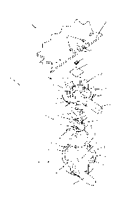
Brief Description of the Drawings
The invention will now be described with reference
to the schematic drawings, wherein Figure 1 shows an
exploded view of a flowmeter and PCB according to the
invention.
Detailed description
Figure 1 shows a flowmeter 1 typically for a
beverage preparation machine, such as a coffee machine.
The flowmeter may be mounted in the fluid circuit of the
beverage preparation machine as for example described in
greater details in WO 2009/130099.
Flowmeter 1 has an outermost casing formed of two
assembled moulded bodies 2,4 delimiting an internal
generally cylindrical measuring chamber 10. For example,
the casing is formed by injection moulding.
Each of the moulded bodies 2,4 has a through-opening
communicating with measuring chamber 10 for circulating
liquid through such flowmeter. In particular, a tubular
inlet 47 is provided in cup-like body 4 and a tubular
outlet 27 is provided in cover body 2. The inlet and the
outlet could of course be switched. Moreover, the inlet
and the outlet could be located on the same moulded body.
These inlet and outlet have a relative position depending
on the position of the first and second bodies.
CA 02781748 2012-05-23
WO 2011/067181
PCT/EP2010/068293
- 11 -
Casing 2,4 contains a rotatable measuring body 3 in
the form of a rotor or impeller. Body 3 has a series of
radial members 31, e.g. fins or blades, on a rotatable
shaft 32 extending centrally across the measuring chamber
10. Shaft 32 has a lower part 33 from which radial
members 31 extend and an upper part 34. Two cavities 35
are provided in upper part 34 for casing a pair of
magnets 36 of corresponding shape. Shaft 32 or body 3 may
be manufactured by injection moulding as well.
Flowmeter 1 has upper and lower point bearings for
mounting opposite extremities 32',32" of rotatable shaft
32 in casing bodies 2,4. These point bearings are formed
by protrusions of casing 2,4 extending into chamber 10
and by recesses in extremities 32',32" of rotatable
shaft 32 forming a positioning counter-part for the
protrusion, a lower protrusion in the form of a pin 11
and an upper recess 37 of this type forming part of the
lower and upper bearings can be seen in Fig. 1. The lower
and upper bearings are identical to ensure similar
performance in all possible orientations.
Protrusions 11 and counter-parts 37 are integrally
formed with the moulded casing bodies 2,4 and the
rotatable shaft 32, respectively. In other words no
additional component is needed for forming the bearing
parts of the flowmeter. These may be moulded directly
with the respective components, i.e. casing bodies 2,4
and shaft 32. The shaft or even the entire impeller 3
(except magnets 36) can be made of PON; casing 2,4 can be
made of PBT with 30 vol% glass beads and/or fibers as a
filler material.
As illustrated in Fig. 1, lower casing body 4 is in
the general shape of a cup and upper casing body 2 is in
the general shape of a cover or lid. It is understood
that the 'lower" and "upper" references merely refer to
the particular orientation of flowmeter 1 as illustrated
in Fig. 1. During use, flowmeter 1 may take any
orientation or even change orientation.
Rotatable shaft 32 has a rotation axis 3' that
extends between a point bearing (not shown) located at
cover body 2 and a facing point bearing 11 located in
cup-like body 4.
CA 02781748 2012-05-23
WO 2011/067181
PCT/EP2010/068293
- 12 -
The rotation of a measuring body 3 by the flow
through chamber 10 drives magnets 36 around axis 3'. The
rotating magnetic field generated by the rotation of
magnets 36 forms a signal representative of this flow
through the adjacent cover body 2 of the flowmeter's
casing to an outermost face 20 thereof.
Cup-like body 4 has a rim 41 forming a reference
surface 42 perpendicular to rotation axis, cover body 2
having an inner face 22 that is urged on reference
surface 42 for precisely setting a spacing between the
point bearings 11 so as to hold and allow free rotation
of shaft 32 therebetween. Inner face 22 and reference
surface 42 form a contact portion 22,42 of the bayonet
connector.
Furthermore, rim 41 has an upright inner surface 43
cooperating with a corresponding seal lip 23 of cover
body 2 for sealing cover body 2 on cup body 4 by force-
fitting of lip 23 into rim 41. This assembly and possible
variations are shown in greater details in the
abovementioned EP 09 163 815.5 and EP 09 163 813Ø
Cup-like body 4 has four spaced apart hooks 45,45a
that are generally evenly distributed on rim 41 and
contact portion 22,42 and that
cooperate with
corresponding passages 25,25a and hook retaining parts 26
at the periphery of cover body 2 to form a bayonet
connection.
Hooks 45,45a and hook-retainers 26 with associated
hook-passages 25,25a form the pairs of interconnecting
securing parts of the bayonet connector for assembling
the casing's bodies 2,4. Hooks 45,45a are arranged to
pass their corresponding hook-passage 25,25a and then
engage with their hook-retainer 26 at assembly. Hooks
45,45a and hook-retainers 26 are in a resilient
respective relationship so as to permit and secure the
connection. The interconnecting securing parts can be
configured to allow non-destructive disassembly.
Alternatively, they may be configured so that a
disassembly possibility is not provided and would
normally lead to destruction of the bayonet connection
and/or at least one casing portion.
CA 02781748 2012-05-23
WO 2011/067181
PCT/EP2010/068293
- 13 -
As the locking movement at bayonet connector of
cover body 2 on cup body 4 is in a plane perpendicular to
shaft 32 and rotational axis 3', the spacing between the
point bearings is not affected by this locking. This
spacing is entirely determined by the geometry (and
position) of contact portion 22,42 relatively to the
location of the point bearings so that tight tolerances
for the bearings can be provided even though they are
formed by moulding and not by additional diamonds. Hooks
45,45a, hook-passages 25,25a as well as hook-retainers 26
are integrally formed with casing bodies 2,4.
The pairs of interconnecting securing parts, e.g.
hooks 45,45a and hook-retainers 25,25a, are arranged so
that the casing bodies 2,4 are assemblable in only one
position in the embodiment shown in Fig. 1. Such a
configuration prevents any erroneous assembly of
flowmeter 1 that would not be compatible with a
connection of the flowmeter onto PCB 50.
For instance, the interconnecting securing parts of
each pair have cooperating shapes for interconnection
thereof, the pairs of securing parts having at least two
different kinds of cooperating shapes formed so that a
securing part of a pair of a first kind is incompatible
with a corresponding securing part of another kind.
In a variation, it is of course possible to have a
symmetric arrangement of the interconnecting securing
parts to allow any number of orientations of the assembly
of the casing bodies.
In the particular embodiment of Fig. 1, a pair of
interconnecting securing parts of a first type of first
dimensions has a hook 45 interconnectable via a hook-
passage 25 with a hook-retainer 26. A pair of
interconnecting securing parts of a second type of second
dimensions has a hook 45a interconnectable via a hook-
passage 25a with a hook-retainer 26. Hook 45a of the
second type is incompatible with hook-passage 25 and/or
hook-retainer 26 of the first type. For example, hook 45a
of the second type is too large to pass via hook-passage
25 of the first type to reach retainer 26.
Hook 45a of second type is generally similar to hook
of the first type. However, hook 45a of the second
CA 02781748 2012-05-23
WO 2011/067181
PCT/EP2010/068293
- 14 -
type has a greater length than hook 45 of the first type,
measured along rim 41 or contact portion 22,42. The
increased length results from the longer base of hook 45a
due to the presence of a hump 45b. Peripheral passage 25
is long enough to let hook 45 pass. However, passage 25
is to short to let hook 45a with hump 45b pass. Hook 45a
with hump 45h may only pass via its dedicated passage 25a
that has a length which is increased compared to passage
25 and adapted to the dimensions of hook 45a with hump
45b.
It follows that the only assembly position accepted
by body 2 against body 4 is the position resulting from
the passage of hook 45a with hump 45b through passage
25a. No other assembly position is possible with the
bayonet configuration shown in Fig. 1.
In another variation it is of course possible to
have two kinds of pairs of interconnecting securing parts
in which the dimensional differences reside concern the
hook-retainer with corresponding differences at the level
of the hook and/or a retainer-passage.
In a further variation, it is possible to provide
facing identical pairs of interconnecting securing parts
distributed so as to allow a number of assembly
configurations that is equal to half the number of pairs
of interconnecting securing members.
For example, the embodiment shown in Fig. 1 can be
modified by replacing hook 45 facing hook 45a across body
4 by a hook 45a with hump 45b and provide a corresponding
substitution of passages 25 and 25a in body 2. With such
a configuration, bodies 2 and 4 accept two assembly
positions, namely a first configuration with inlet 47 and
outlet 27 on the same side of flowmeter 1 and a second
configuration with inlet 47 and outlet 27 on opposite
sides of flowmeter 1, and no further assembly
configuration, despite the presence of four pairs of
hooks and retainers.
Furthermore, flowmeter 1 is arranged to cooperate
with control unit 5, typically a control unit of a
beverage preparation machine.
CA 02781748 2012-05-23
WO 2011/067181
PCT/EP2010/068293
- 15 -
Control unit 5 has a PCB 50 including a sensor 51.
Sensor 51 can be a discrete component that is welded or
mechanically and electrically assembled directly onto the
surface of PCB 50. Alternatively, the sensor may be
directly integrated into the PCB. Hence, sensor 51 is not
remotely located relative to PCB 50 and does not need any
flexible wires or cables for its connection.
Furthermore, flowmeter 1 has a
connection
arrangement 28 for fastening outermost casing 2,4 against
PCB 50. This PCB extends over and beyond casing 2,4. Upon
fastening of flowmeter 1 on PCB 50, sensor 51 is located
adjacent outermost face 20 and is configured to sense the
magnetic signal generated by magnets 36 rotating with
rotatable body 3 under the effect of a flow through
chamber 10.
In accordance with the invention,
connection
arrangement 28 is configured for connection of flowmeter
1 against casing 2,4, which connection between the PCB
and the casing is distinct from sensor 51. In particular,
connection arrangement 28 is located outside a sensor
area 29 for receiving sensor 51 upon connection. This
sensor area is formed by a recess 29 in outermost face
20. Hence, upon assembly of flowmeter 1 onto PCB 50,
sensor 51 is directly exposed to the magnetic filed
generated by magnets 36 rotating with measuring body 3
with a flow of e.g. liquid through measuring chamber 10.
To detect variations of the amplitude of the magnetic
field adjacent to outermost face 20, sensor 51 may be of
the Hall type.
Casing cover 2 further comprises a spacer 28' for
spacing outermost face 20 from PCB 50. Upon assembly of
flowmeter 1 on PCB 50, spacer 28' rests against PCB.
Thereby, a sufficient spacing can provided at all time
between outermost face 20 with recess 29 and PCB 50 to
prevent that sensor 51 located therebetween gets squeezed
and subject to unnecessary constraints. Hence, sensor 51
is maintained at a distance or contactless from the
flowmeter's casing 2,4.
The connection arrangement includes a pair of semi-
rigid resilient members 28 extending upright from
outermost face 20. Members 28 are suitable to be fastened
CA 02781748 2012-05-23
WO 2011/067181
PCT/EP2010/068293
- 16 -
to PCB 50 via corresponding through-openings 58 forming
anchorage holes for members 28. Members 28 are arranged
about an inner area 29 of the outermost face 20. This
inner area faces sensor 51 upon connection.
PCB 50 has peripheral cut-outs 59 and a resiliently
deformable intermediate member 59' against which spacer
28' of flowmeter 1 is urged to ensure looseness free
assembly of flowmeter 1 against PCB 50. Thereby, the
accuracy of the measured flow via flowmeter 1 is
maintained over time.
In a variation, it is possible to use an adhesive
material to secure flowmeter 1 against PCB 5 or to weld
flowmeter thereagainst, e.g. via spacer 28'.
Casing 2,4 is covered with an insulating layer 52 of
Polyimide in the vicinity of sensor 51. Layer 52 may be
pre-applied onto outermost face 20 or over sensor 51, in
particular using an adhesive bonding material.
During use of flowmeter 1, liquid is circulated from
inlet 47 to outlet 27 via chamber 10. The flow of liquid
will be intercepted by blades 31 thus driving shaft 32 in
rotation about axis 3' between the point bearings at
extremities 32',32" of shaft 32. The speed of rotation
of shaft 32 will be proportional to the flow of liquid in
chamber 10 and driving measuring body 3. By rotating
shaft 32, magnets 36 are rotated adjacent to the Hall
sensor 51 on PCB 50 and located in recess 29 of the
flowmeter's outermost face 20. The Hall sensor will
detect the rotating magnetic field generated by the
magnets and convert it into a corresponding electric
signal having a frequency corresponding to the speed of
rotation of shaft 32.