Note: Descriptions are shown in the official language in which they were submitted.
WO 2011/066466 PCT/US2010/058109
ACTUATOR WITH THRUST FLANGES AND LATERALLY TILTABLE TOOL
ASSEMBLY USING SAME
BACKGROUND OF THE INVENTION
Field of the Invention
The present invention relates generally to actuators and laterally tiltable
tool
assemblies, and more particularly, to fluid-powered rotary actuators in which
axial
movement of a piston results in relative rotational movement between a body
and a
shaft, and laterally tiltable tool assembly using same.
Description of the Related Art
Rotary helical splined actuators have been employed in the past to achieve the
advantage of high-torque output from a simple linear piston-and-cylinder drive
arrangement. The actuator typically uses a cylindrical body with an elongated
rotary
output shaft extending coaxially within the body, with an end portion of the
shaft
providing the drive output. An elongated annular piston sleeve has a sleeve
portion
splined to cooperate with corresponding splines on the body interior and the
output
shaft exterior. The piston sleeve is reciprocally mounted within the body and
has a
piston head portion for the application of fluid pressure to one or the other
opposing
sides thereof to produce axial movement of the piston sleeve.
As the piston sleeve linearly reciprocates in an axial direction within the
body,
outer helical splines of the sleeve portion engage helical splines of the body
to cause
rotation of the sleeve portion. The resulting linear and rotational movement
of the
sleeve portion is transmitted through inner helical splines of the sleeve
portion to helical
splines of the shaft to cause the shaft to rotate. Bearings are typically
supplied to
rotatably support one or both ends of the shaft relative to the body.
Reducing the cost and size of fluid-powered rotary actuators and increasing
their
durability are an almost always present challenge. This challenge is
applicable when
manufacturing a laterally tiltable tool assembly to be connected to an
extendable or
articulated arm of a backhoe, excavator and similar type vehicle and using a
fluid-
powered rotary actuator to provide the rotational drive for laterally tilting
a bucket or
other tool attached to the tool assembly. Such laterally tiltable tool
assemblies are used
1
WO 2011/066466 PCT/US2010/058109
under harsh conditions where debris, dust, dirt and moisture is most often
present and
experience high load conditions.
It will be therefore be appreciated that there has long been a significant
need for
fluid-powered rotary actuators that require less expensive to manufacture, has
a
reduced length and is durable. The present invention fulfills these needs and
further
provides other related advantages.
BRIEF DESCRIPTION OF THE SEVERAL VIEWS OF THE DRAWING(S)
FIG. 1 is a front right side perspective view of an excavator shown with one
version of a laterally tiltable tool assembly with a fluid-powered rotary
actuator
embodying the present invention, shown with a bucket attached and showing
other
attachable tools on the ground.
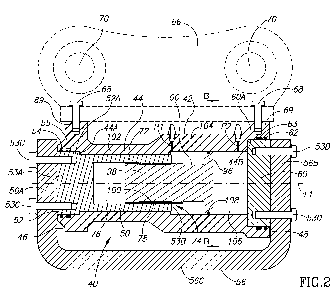
FIG. 2 is an enlarged, fragmentary, right side, cross-sectional view of a
first
embodiment of the tool assembly of FIG. 1, shown taken substantially along the
line A--
A of FIG. 2A.
FIG. 2A is a partial rear end view of the tool assembly of Figure 2.
FIG. 2B is a partial cross-sectional view of the tool assembly of Figure 2,
shown
taken substantially along the line B--B of FIG. 2.
FIG. 3 is an enlarged, fragmentary, right side, cross-sectional view of a
second
embodiment of the rotary actuator useable with the tool assembly of FIG. 1,
shown
taken substantially along the line A--A of FIG. 3A.
FIG. 3A is a rear end view of the rotary actuator of Figure 3.
FIG. 3B is a cross-sectional view of the rotary actuator of Figure 3, shown
taken
substantially along the line B--B of FIG. 3.
FIG. 4 is an enlarged, fragmentary, left side, cross-sectional view of a third
embodiment of the rotary actuator useable with the tool assembly of FIG. 1,
shown
taken substantially along the line A--A of FIG. 4A.
FIG. 4A is a rear end view of the rotary actuator of Figure 4.
FIG. 4B is a cross-sectional view of the rotary actuator of Figure 4, shown
taken
substantially along the line B--B of FIG. 4.
FIG. 5 is an enlarged, fragmentary, right side, cross-sectional view of a
fourth
embodiment of the rotary actuator useable with the tool assembly of FIG. 1,
shown
taken substantially along the line A--A of FIG. 5A.
2
WO 2011/066466 PCT/US2010/058109
FIG. 5A is a rear end view of the rotary actuator of Figure 5.
FIG. 5B is a cross-sectional view of the rotary actuator of Figure 5, shown
taken
substantially along the line B--B of FIG. 5 using an oval piston head and a
concentric
shaft.
FIG. 5B-1 is a cross-sectional view of the rotary actuator of Figure 5, shown
taken substantially along the line B--B of FIG. 5 using a square piston head
and a
concentric shaft.
FIG. 5B-2 is a cross-sectional view of the rotary actuator of Figure 5, shown
taken substantially along the line B--B of FIG. 5 using a cylindrical piston
head and an
eccentric shaft.
DETAILED DESCRIPTION OF THE INVENTION
As shown in the drawings for purposes of illustration, a first embodiment of
the
invention is embodied in a fluid-powered, laterally tiltable tool assembly,
indicated
generally by reference numeral 10, and a fluid-powered rotary actuator,
indicated
generally by reference numeral 40. As shown in FIG 1, the tool assembly 10 is
usable
with a vehicle 12, such as the illustrated excavator or any other suitable
type vehicle
such as a backhoe that might use a bucket or other tool as a work implement.
The
vehicle 12 has a first arm 14 which is pivotally connected by one end to a
base member
(not shown) forming a part of the platform 12A of the vehicle. A pair of
hydraulic
cylinders 16 and 18 are provided for raising and lowering the first arm in a
generally
forwardly extending vertical plane with respect to the base member. A second
arm 20
is pivotally connected by one end to an end of the first arm 14 remote from
the base
member. A hydraulic cylinder 22 is provided for rotation of the second arm 20
relative
to the first arm 14 in the same vertical forward rotation plane as the first
arm operates.
The platform 12A of the vehicle 12 is pivotally mounted and supported by a
track
drive undercarriage 12B and is pivotally movable about a vertical axis so as
to permit
movement of the first and second arms 14 and 20 in unison to the left or
right, with the
first and second arms always being maintained in the forward rotation plane.
It is noted
that while the forward rotation plane is referred to as being forwardly
extending for
convenience of description, as the platform 12A is pivoted relative to the
track drive, the
forward rotation plane turns about the vertical pivot axis of the track drive
and thus to a
certain extent loses its forward-to-rearward orientation, with the plane
actually
3
WO 2011/066466 PCT/US2010/058109
extending laterally relative to the undercarriage 12B should the platform be
sufficiently
rotated.
A rotation link 24 is pivotally connected through a pair of interconnecting
links 26
to an end portion 28 of the second arm 20 remote from the point of attachment
of the
second arm to the first arm 14. A hydraulic cylinder 30 is provided for
selective
movement of the rotation link 24 relative to the second arm 20.
As is conventional, a free end portion 31 of the second arm 20 and a free end
portion 32 of the rotation link 24 each has a transverse aperture therethrough
for
connection of the second arm and the rotation link to a conventional tool such
as a
bucket using a pair of selectively removable attachment pins 33. The
attachment pins
33 are insertable in the apertures to pivotally connect the conventional tool
directly to
the second arm and the rotation link. When using the conventional tool, this
permits the
tool to be rotated about the attachment pin of the second arm 20 upon movement
of the
rotation link 24 relative to the second arm as a result of extension or
retraction of the
hydraulic cylinder 30 to rotate the conventional tool in the forward rotation
plane defined
by the first and second arms 14 and 20.
In the embodiment of the invention shown in Figure 1, a conventional bucket 34
of relatively narrow width is utilized. The bucket has a toothed working edge
35
extending laterally, generally transverse to the forward rotation plane of the
bucket.
The bucket 34 further includes a first and second bucket clevises 36 and 38,
with the
first bucket clevis located toward the bucket working edge 35 and second
bucket clevis
38 located forwardly of the first bucket clevis and away from the bucket
working edge.
The first and second bucket clevises are in general parallel alignment with
the forward
rotation plane of the bucket. It should be understood that the present
invention may be
practiced using other tools as work implements, and is not limited to just
operation with
buckets.
The tool assembly 10 includes the fluid-powered rotary actuator 40. One
version
of the rotary actuator 40 is shown in FIGS. 2, 2A and 2B. The rotary actuator
40 has an
elongated housing or body 42 with a body sidewall 44 and first and second body
ends
46 and 48, respectively. An axially outward facing first body end shoulder 44A
is
located axially inward from the first body end 46, and an axially outward
facing second
body end shoulder 44B is located axially inward from the second body end 48.
An
elongated rotary drive or output shaft 50 is coaxially positioned within the
body 42 and
supported for rotation relative to the body about a longitudinal axis L1.
4
WO 2011/066466 PCT/US2010/058109
The shaft 50 extends partially along length of the body 42 from the first body
end
46 to about midway to the second body end 48, and has a flange portion 52 at
the first
body end 46 with an axially inward facing flange shoulder 52A in sliding
engagement
with the axially outward facing first body end shoulder 44A of the body
sidewall 44. The
shaft has a shaft first end portion 53A at the first body end 46 which extends
axially
outward beyond the first body end and a shaft second end portion 53B toward
the
second body end 48.
An exclusion seal 54 and a pressure seal 55 are disposed between the periphery
of the shaft flange portion 52 and the body sidewall 44 at the first body end
46 to
provide a fluid-tight seal and containment seal therebetween. The shaft flange
portion
52 engages body 42 at the first body end 46 in the area between the pressure
seal 55
and its axially inward facing flange shoulder 52A for sliding rotary motion
and radial
load transfer.
A saddle or "C"-shaped attachment frame 56 is positioned outward of the body
42 and has a first end leg 56A at the first body end 46 and a second end leg
56B at the
second body end 48, with a mid-portion member 56C spanning between the first
and
second end legs. The first end leg 56A is rigidly attached to the shaft first
end portion
53A at the first body end 46 for rotation with the shaft 50 relative to the
body 42, with
the first end leg being spaced axially apart from the first body end. The
first end leg
56A abuts against an outward end face of the shaft first end portion 53A for
support and
is bolted thereto by a plurality of circumferentially arranged bolts 53C (only
two being
illustrated in Figure 2).
The attachment frame 56 has the rotational drive of the shaft 50 transmitted
thereto so as to provide the torque needed for tilting the bucket 34 (or other
tool
attached to the tool assembly 10) to the desired lateral tilt angle and for
holding the
bucket in that position while the bucket performs the desired work. The
attachment
frame 56 does not move axially relative to the body 42.
The first end leg 56A and the second end leg 56B of the attachment frame 56
extend radially beyond the body sidewall 44 generally downwardly toward the
bucket
34. The mid-portion member 56C extends between the first and second end legs
56A
and 56B and is rigidly attached thereto, and extends generally parallel to the
body
sidewall 44 at a position below the body sidewall. The mid-portion member 56C
of the
attachment frame 56 is configured to be rigidly attached to a tool attachment
assembly
(not shown) spaced below and away from the rotary actuator 40 which can be
operated
WO 2011/066466 PCT/US2010/058109
to achieve releasable attachment thereto of a tool such as the bucket 34 shown
in
Figure 1. Where the rotary actuator 40 of the present invention is not used in
a laterally
titlable tool assembly 10 such as described above, the mid-portion member 56C
may
be affixed to another first device or structure and the body 42 attached to
different
second device or structure to accomplish relative rotational movement between
the first
device or structure and the second device or structure.
An end cap 60 is rotatably mounted within the body 42 at the second body end
48 and extends axially outward beyond the second body end. The end cap 60 has
an
axially inward facing end cap shoulder 60A in sliding engagement with the
axially
outward facing second body end shoulder 44B of the body sidewall 44. The
second
end leg 56B of the attachment frame 56 abuts against an outward end face of
the end
cap 60 and is bolted thereto by a plurality of circumferentially arranged
bolts 53D, with
five bolts 53D illustrated in Figure 2A.
An exclusion seal 62 and a pressure seal 63 are disposed between the periphery
of the end cap 60 and the body sidewall 44 at the second body end 48 to
provide a
fluid-tight seal and containment seal therebetween. The end cap 60 engages the
body
42 at the second body end 48 in the area between the pressure seal 63 and its
axially
inward facing end cap end cap shoulder 60A for sliding rotary motion and
radial load
transfer. The second end leg 56B of the attachment frame 56 is rigidly
attached to the
end cap 60 at the second body end 48 with the second end leg being spaced
axially
apart from the second body end. Through the attachment frame 56, the end cap
60 is
effectively attached to the shaft first end portion 53A of the shaft 50 at the
first body end
46 and the rotational drive the shaft applies to the attachment frame is
transmitted by
the second end leg 56B to the end cap such that the end cap rotates with the
shaft 50
relative to the body 42.
The tool assembly 10 includes a pair of attachment brackets 66 rigidly
attached
to the body 42 of the rotary actuator 40 by a plurality of bolts 68, each of
which
threadably engage an interiorly threaded attachment 69 of the body. The
attachment
brackets 66 are used to detachably connect the tool assembly 10 to the second
arm 20
and the rotation link 24 in a position therebelow in general alignment with
the forward
rotation plane, much in the same manner as a conventional bucket would be
attached.
The attachment brackets 66 form first and second attachment clevis with
apertures 70
therein each sized to receive one of the attachment pins 33 to pivotally
connect the tool
assembly 10 to the vehicle second arm 20 at its free end portion 31, and to
pivotally
6
WO 2011/066466 PCT/US2010/058109
connect the tool assembly to the rotation link 24 at its free end portion 32.
By the use
of selectively removable attachment pins 33, the tool assembly 10 can be
removed
from the second arm 20 and the rotation link 24 when use of the tool assembly
is not
desired.
The shaft 50 has an annular second end shaft portion 72 extend from the shaft
first end portion 53A toward the second body end 48. The second end shaft
portion 72
has an opening 74 at its end toward the second body end and defines an open
ended
cylindrical in cross-sectional shape, interior chamber 76 coaxial with the
body sidewall
44. A portion of the length of the interior chamber 76, toward the second body
end 48,
has inner helical splines 78.
The rotary actuator 40 uses a piston 90 coaxially and reciprocally mounted
within
the body 42 coaxially with the shaft 50. The piston 90 has a piston head 96
toward the
second body end 48 and a splined portion 98 rigidly attached to the piston
head and
extending therefrom toward the first body end 46. The splined portion 98 is
sized to
extend within the interior chamber 76 of the second end shaft portion 72 of
the shaft 50
and has outer helical splines 100 over a portion of its length which slidably
mesh with
inner helical splines 78 of the interior chamber 76 of the shaft 50. It should
be
understood that while splines are shown in the drawings and described herein,
the
principle of the invention is equally applicable to any form of linear-to-
rotary motion
conversion means, such as balls or rollers, or other means.
In the first embodiment of the invention illustrated in Figure 2, the piston
head 96
of the piston 90 is non-cylindrical in cross-sectional shape and positioned
toward the
second body end 48. The piston head 96 is slidably maintained within the body
42 for
reciprocal movement, and undergoes longitudinal but not rotational movement
relative
to the body sidewall 44. The body sidewall 44 of the body 42 of the rotary
actuator 40
of this embodiment has a first end body sidewall portion 102 which is
cylindrical in
cross-sectional shape and extends from the first body end 46 to a body mid-
portion,
and a second end body sidewall portion 104 which has an exterior wall surface
which is
cylindrical in cross-sectional shape and an interior wall surface which is non-
cylindrical
in cross-sectional shape and extends from the axially outward facing second
body end
shoulder 44B to the body mid-portion where the first and second end body
sidewall
portions are joined together. The second end body sidewall portion 104 defines
an
interior chamber 106 which is non-cylindrical in cross-sectional shape and
sized to
slidably receive the piston head 96 therein. The interior sidewall surfaces of
the first
7
WO 2011/066466 PCT/US2010/058109
and second end body sidewall portions 102 and 104 are smooth. The piston head
96
of the piston 90 is disposed for reciprocation within only the non-cylindrical
interior
chamber 106 of the second end body sidewall portion 104 and has a perimeter
with a
cross-sectional shape corresponding to the non-cylindrical shape of the
interior
chamber 106 so as to be in sliding engagement therewith, in this case the
piston head
96 and the interior chamber 106, as well as the second end body sidewall 104,
are oval
as shown in Figure 2B. The splined portion 98 of the piston 90 is cylindrical
in shape.
The annular second end shaft portion 72 of the shaft 50 of the rotary actuator
40
in this embodiment is cylindrical in cross-sectional shape and extends toward
the
second body end 48 about the same length as the first end body sidewall
portion. The
second end shaft portion 72 has a smooth exterior sidewall surface and is
coaxially
disposed within in the smooth-walled, cylindrical first end body sidewall
portion 102 for
rotation therewithin.
A seal 108 is carried by the piston head 96 of the piston 90 and disposed
between the piston head and the smooth interior sidewall surface of the second
end
body sidewall portion 104 of the body sidewall 44 to provide a fluid-tight
seal
therebetween.
As will be readily understood, reciprocation of the piston 90 within the body
42 of
the rotary actuator 40 occurs when hydraulic fluid, such as oil, air or any
other suitable
fluid, under pressure selectively enters through one or the other of a first
port P1 which
is in fluid communication with a fluid-tight compartment within the body
defined to a side
of the piston head 96 toward the first body end 46 or through a second port P2
which is
in fluid communication with a fluid-tight compartment within the body to a
side of the
piston head toward the second body end 48. The application of fluid pressure
to the
first port P1 produces axial movement of the piston 90 toward the second body
end 48.
The application of fluid pressure to the second port P2 produces axial
movement of the
piston 90 toward the first body end 46. The rotary actuator 40 provides
relative
rotational movement between the body 42 and shaft 50 through the conversion of
linear
movement of the piston 90 into rotational movement of the shaft. The shaft 50
is
selectively rotated by the application of fluid pressure, and the rotation is
transmitted to
the bucket 34 or other tool to selectively tilt the attached bucket or other
tool laterally,
left and right.
When hydraulic fluid under pressure is selectively applied to the first port
P1 or
the second port P2, the piston 96 will move longitudinally within the second
end body
8
WO 2011/066466 PCT/US2010/058109
sidewall portion 104, but the matching non-cylindrical shapes of the piston
head 96 and
the second end body sidewall portion prevent the rotation of the piston.
Linear
reciprocation of the piston head 96 in an axial direction within the second
end body
sidewall portion 104 of the body 42 of the rotary actuator 40, with the outer
helical
splines 100 of the splined portion 98 of the piston 90 engaging and meshing
with the
inner helical splines 78 of the interior chamber 76 of the shaft 50, causes
the shaft to
alternately rotate clockwise and counterclockwise. The axial movement of the
piston 90
is converted into rotational movement of the shaft 50 through the interaction
of the outer
helical splines 100 of the splined portion 98 of the piston and the inner
helical splines
78 of the interior chamber 76 of the shaft 50 because axial movement of the
shaft is
restricted. The axial movement of the shaft 50 in the direction of the second
body end
48 is restricted by the axially inward facing flange shoulder 52A of the
flange portion 52
of the shaft engaging the axially outward facing first body end shoulder 44A
of the body
sidewall 44 when axial force is experienced on the shaft in the direction of
the second
body end 48, and axial movement of the shaft 50 in the direction of the first
body end
46 is restricted by the axially inward facing end cap shoulder 60A engaging
the axially
outward facing second body end shoulder 44B of the body sidewall when axial
force is
experienced on the shaft in the direction of the first body end 46 (the axial
force in the
direction of the first body end being transmitted to the end cap 60 by the
attachment
frame 56). The attachment frame 56 is sufficiently rigid and strong that
limiting the axial
movement of the end cap 60 toward the first body end 46 also limits the axial
movement of the shaft 50 toward the first body end and retains the shaft
within the body
42.
Since the shaft 50 cannot move in the axial direction, the interaction of the
outer
helical splines 100 and the inner helical splines 78 resulting from the axial
movement of
the piston 90 toward the second body end 48 when fluid pressure is applied to
the first
port P1 is converted into a rotational force on the shaft which drives the
shaft to rotate
in the clockwise or counterclockwise rotational direction depending on the
direction of
turn of the outer helical splines 100 and the inner helical splines 78, and
when resulting
from the axial movement of the piston toward the first body end 46 when fluid
pressure
is applied to the second port P2 is converted into a rotational force on the
shaft which
drives the shaft to rotate in the opposite rotational direction. Thus, all
movement of the
piston 90 is converted into rotational movement of the shaft 50. The
rotational
movement of the shaft 50 is transmitted by the shaft flange portion 52 to the
attachment
9
WO 2011/066466 PCT/US2010/058109
frame 56 and the tool attachment assembly (not shown) with the bucket 34 or
other tool
attached thereto, which results in lateral tilting of the bucket or other tool
to the right or
left.
The thrust loading of the actuator is now discussed. When fluid pressure is
applied to the first port P1 to produce axial movement of the piston 90 toward
the
second body end 48, the pressurized fluid pushes the piston 96 in the axial
direction
toward the second body end 48 and transfers most of the load into the shaft 50
through
the outer helical splines 100 of the splined portion 98 of the piston engaging
the inner
helical splines 78 of the interior chamber 76 of the shaft, thus biasing the
shaft toward
the second body end. This tends to engage the axially inward facing flange
shoulder
52A with the axially outward facing first body end shoulder 44A at the first
body end 46.
The same pressurized fluid simultaneously also acts directly on the shaft
flange portion
52 of the shaft 50, although in the opposite axial direction, to push it in
the axial
direction toward the first body end 46, thus biasing the shaft toward the
first body end.
This force is transmitted by the attachment frame 56 to the end cap 60 as an
axial force
in the direction toward the first body end and tends to engage the axially
inward facing
end cap shoulder 60A with the axially outward facing second body end shoulder
44B at
the second body end 48. The net difference, adjusted for the frictional losses
within the
actuator 40 and the external force being applied to the shaft, determines the
amount of
axial force experienced by the thrust surfaces of the actuator, and whether
the thrust
surfaces at the first body end 46 or at the second body end 48 experience that
axial
force, i.e., either the axially inward facing flange shoulder 52A engaging the
axially
outward facing first body end shoulder 44A at the first body end 46, or the
axially inward
facing end cap shoulder 60A engaging the axially outward facing second body
end
shoulder 44B at the second body end 48. Since the area of the shaft flange
portion 52
(defined by the diameter thereof) is only slightly smaller than the area of
the piston 96
and since some force is lost to internal friction of the actuator 40, a
relatively small net
thrust force results from fluid pressure applied to the first port P1.
When fluid pressure is applied to the second port P2 to produce axial movement
of the piston 90 toward the first body end 46, the pressurized fluid pushes
the piston 96
in the axial direction toward the first body end 46 and transfers most of the
load into the
shaft 50 through the outer helical splines 100 of the splined portion 98 of
the piston
engaging the inner helical splines 78 of the interior chamber 76 of the shaft,
thus
biasing the shaft toward the first body end. This force is transmitted by the
attachment
WO 2011/066466 PCT/US2010/058109
frame 56 to the end cap 60 as an axial force in the direction toward the first
body end
and hence would be experienced by the axially inward facing end cap shoulder
602A
engaging the axially outward facing second body end shoulder 44B at the second
body
end 48. However, the same pressurized fluid simultaneously also acts directly
on the
end cap 60, although in the opposite axial direction, to push it in the axial
direction
toward the second body end 48. Since the area of the end cap 60 (defined by
the
diameter thereof) is significantly greater than the area of the piston 96, the
net thrust
force resulting from fluid pressure applied to the second port P2 is axially
outward in the
axial direction toward the second body end 48 and is transmitted by the
attachment
frame 56 to the shaft flange portion 52 as an axial force in the direction
toward the
second body end, hence the net thrust force is experienced by the axially
inward facing
flange shoulder 52A engaging the axially outward facing first body end
shoulder 44A at
the first body end 46.
As the shaft 50 rotates, the axially inward facing flange shoulder 52A of the
flange portion 52 can slide along the axially outward facing first body end
shoulder 44A
under a net axial thrust load in the axial direction of the second body end
48, and the
axially inward facing end cap shoulder 60A of the end cap 60 can slide along
the axially
outward facing first body end shoulder 44B under a net axial thrust load in
the axial
direction of the first body end 46. While discussed above primarily with
respect to the
thrust forces experienced by the actuator 40 as a result of applying fluid
pressure to the
first and second ports P1 and P2, the thrust surfaces of the actuator (i.e.,
the thrust
surfaces at the first body end 46 - the axially inward facing flange shoulder
52A
engaging the axially outward facing first body end shoulder 44A and the thrust
surfaces
at the second body end 48 - the axially inward facing end cap shoulder 60A
engaging
the axially outward facing second body end shoulder 44B) also take up the
axial loading
experienced by the actuator from external sources such as loads on the bucket
34 or
other tool attached to the tool assembly 10 and other loading experienced
during
operation of the actuator.
The pressure seal 55, which provides the fluid-tight seal therebetween the
shaft
flange portion 52 and the body sidewall 44 at the first body end 46, is
located axially
outward of the axially inward facing flange shoulder 52A and the axially
outward facing
first body end shoulder 44A so that the fluid applied to the first port P1 to
produce axial
movement of the piston 90 toward the second body end 48 also lubricates the
inward
facing flange shoulder 52A and the axially outward facing first body end
shoulder 44A
11
WO 2011/066466 PCT/US2010/058109
to reduce the friction therebetween and the wear resulting from the shaft 50
rotating.
Further, the location of the seals 54 and 55 also places the area of
engagement of the
axially inward facing flange shoulder 52A with the axially outward facing
first body end
shoulder 44A within the sealed interior of the body 42 and thereby prevents
debris,
dust, dirt and moisture in the environment from engagement therewith and the
damage
and wear that would cause.
The pressure seal 63, which provides the fluid-tight seal therebetween the end
cap 60 and the body sidewall 44 at the second body end 48, is located axially
outward
of the axially inward facing end cap shoulder 60A and the axially outward
facing second
body end shoulder 44B so that the fluid applied to the second port P2 to
produce axial
movement of the piston 90 toward the first body end 46 also lubricates the
inward
facing end cap shoulder 60A and the axially outward facing second body end
shoulder
44B to reduce the friction therebetween and the wear resulting from the shaft
50
rotating. Further, the location of the seals 62 and 63 also places the area of
engagement of the axially inward facing end cap shoulder 60A with the axially
outward
facing second body end shoulder 44B within the sealed interior of the body 42
and
thereby prevents debris, dust, dirt and moisture in the environment from
engagement
therewith and the damage and wear that would cause.
A second embodiment of the rotary actuator 40 useable as part of the tool
assembly 10, or for other purposes is shown in Figures 3, 3A and 3B. The shaft
50 is
coaxially positioned within the body 42 and supported for rotation relative to
the body
about the longitudinal axis of the body.
A first end cap 110 is threadably attached to the body 42 at the first body
end 46
and a second end cap 112 is attached to the body at the second body end 48 by
a
plurality of circumferentially arranged bolts 114 . The first end cap 110 has
a threaded
exterior perimeter portion 110A threadably attached to a correspondingly
threaded
interior portion 44C of the body sidewall 44 of the body 42 to retain the
first end cap
stationary relative to the body. A pair of seals 116 are disposed between the
first end
cap 110 and the body sidewall 44 at the first body end 46 to provide a fluid-
tight seals
therebetween. A seal 118 is disposed between the second end cap 112 and the
body
sidewall 44 at the second body end 48 to provide a fluid-tight seals
therebetween.
The shaft 50 extends the full length of the body 42 and extends through a
central
aperture 120 in each of the first and second end caps 110 and 112. The shaft
50 has
12
WO 2011/066466 PCT/US2010/058109
an axially outward facing first shaft shoulder 122 located axially inward from
the first
end cap 110, and an axially outward facing second shaft shoulder 124 located
axially
inward from the second end cap 112. An annular axial thrust bearings 126 is
mounted
on the shaft 50 in position between the first end cap 110 and the axially
outward facing
first shaft shoulder 122, and an annular axial thrust bearings 128 is mounted
on the
shaft 50 in position between the second end cap 112 and the axially outward
facing
second shaft shoulder 124. The annular axial thrust bearings 126 and 128
provide
rotational, axial and radial support of the shaft 50 relative to the body 42.
An exclusion
seal 130 and a pressure seal 132 are disposed between the periphery of the
shaft 50
and each of the first and second end caps 110 and 112 to provide a fluid-tight
seal and
containment seal therebetween. The first end cap 110 is locked in place
against
rotation relative to the body 42 during fluid-powered operation of the
actuator 40 by a
stop pin 134.
The shaft 50 extends outward of the body 42 through the apertures 120 in the
first and second end caps 110 and 112, and has splined drive end portions
extending
beyond the first and second end caps for coupling to an external device (not
shown)
such as an attachment frame. It is to be understood that the rotary actuator
40 may be
used with the shaft 40 rotatably driving an external device, or with the shaft
being held
stationary and the rotational drive being provided by rotation of the body 42.
The actuator 40 of the second embodiment of Figures 3, 3A and 3B has a linear-
to-rotary transmission means which includes an annular piston sleeve 138
through
which the shaft 50 extends. The piston sleeve 138 is coaxially and
reciprocally
mounted within the body 42 coaxially about the shaft 50. The piston sleeve 138
has a
piston head 140 toward the second body end 48 with an aperture 140A sized to
receive
the shaft 50 therethrough. The aperture 140A being located coaxial with the
body 42
and the shaft 50. The piston sleeve 138 further includes a splined portion 142
rigidly
attached to the piston head and extending therefrom toward the first body end
46. The
splined portion 142 has inner helical splines 144 over a portion of its length
which
slidably mesh with outer helical splines 146 of a splined intermediate portion
148 of the
shaft 50 located between the first and second end caps 110 and 112, to a side
of the
piston head 140 toward the first body end 46. Again, while splines are shown
in the
drawings and described herein, the principle of the invention is equally
applicable to
any form of linear-to-rotary motion conversion means, such as balls or
rollers, or other
means.
13
WO 2011/066466 PCT/US2010/058109
As in the first embodiment of Figures 2, 2A and 2B, the piston head 140 of
this
second embodiment is non-cylindrical in cross-sectional shape and positioned
toward
the second body end 48. The piston head 140 is slidably maintained within the
body 42
for reciprocal movement, and undergoes longitudinal but not rotational
movement
relative to the body sidewall 44. The body sidewall 44 of the body 42 of the
rotary
actuator 40 of this embodiment has the first end body sidewall portion 102
that is
cylindrical in cross-sectional shape and extends from the first body end 46 to
a body
mid-portion, and has the second end body sidewall portion 104 which is non-
cylindrical
in cross-sectional shape (both the exterior and interior wall surfaces) and
extends from
axially inward of the second body end 48 to the body mid-portion where the
first and
second end body sidewall portions are joined together. The second end body
sidewall
portion 104 defines the interior chamber 106 which is non-cylindrical in cross-
sectional
shape and sized to slidably receive the piston head 140 therein. The interior
sidewall
surfaces of the first and second end body sidewall portions 102 and 104 are
smooth.
The piston head 140 of the piston sleeve 138 is disposed for reciprocation
within only
the non-cylindrical interior chamber 106 of the second end body sidewall
portion 104
and has a perimeter with a cross-sectional shape corresponding to the non-
cylindrical
shape of the interior chamber 106 so as to be in sliding engagement therewith,
in this
case the piston head 140 and the interior chamber 106, as well as the second
end body
sidewall 104, are oval as shown in Figure 3B. The splined portion 142 of the
piston
sleeve 138 is cylindrical in shape.
A pair of outer seals 150 are carried by the piston head 140 and disposed
between the piston head and the smooth interior sidewall surface of the second
end
body sidewall portion 104 of the body sidewall 44 to provide a fluid-tight
seal
therebetween, and a pair of inner seals 152 are carried by the piston head and
disposed between the head portion and a smooth exterior surface portion of the
shaft
50 to provide a fluid-tight seal therebetween.
As for the first embodiment described above, reciprocation of the piston
sleeve
138 within the body 42 of the rotary actuator 40 occurs when hydraulic fluid
under
pressure selectively enters through one or the other of a first port P1 which
is in fluid
communication with a fluid-tight compartment within the body defined to a side
of the
piston head 140 toward the first body end 46 or through a second port P2 which
is in
fluid communication with a fluid-tight compartment within the body to a side
of the
piston head toward the second body end 48. The application of fluid pressure
to the
14
WO 2011/066466 PCT/US2010/058109
first port P1 produces axial movement of the piston sleeve 138 toward the
second body
end 48. The application of fluid pressure to the second port P2 produces axial
movement of the piston sleeve 138 toward the first body end 46. The rotary
actuator 40
provides relative rotational movement between the body 42 and shaft 50 through
the
conversion of linear movement of the piston sleeve 138 into rotational
movement of the
shaft. The shaft 50 is selectively rotated by the application of fluid
pressure, and the
rotation is transmitted to the bucket 34 or other tool to selectively tilt the
attached
bucket or other tool laterally, left and right.
When hydraulic fluid under pressure is selectively applied to the first port
P1 or
the second port P2, the piston sleeve 138 will move longitudinally within the
second end
body sidewall portion 104, but the matching non-cylindrical shapes of the
piston head
140 and the second end body sidewall portion prevent the rotation of the
piston sleeve.
Linear reciprocation of the piston head 140 in an axial direction within the
second end
body sidewall portion 104 of the body 42 of the rotary actuator 40, with the
inner helical
splines 144 of the splined portion 142 of the piston sleeve 138 engaging and
meshing
with the outer helical splines 146 of the splined intermediate portion 148 of
the shaft 50,
causes the shaft to alternately rotate clockwise and counterclockwise. Thus,
all
movement of the piston sleeve 138 is converted into rotational movement of the
shaft
50. The rotational movement of the shaft 50 is transmitted by one or both of
the splined
drive end portions 136 of the shaft 50.
The axial movement of the piston sleeve 138 is converted into rotational
movement of the shaft 50 through the interaction of the inner helical splines
144 of the
splined portion 142 of the piston sleeve and the outer helical splines 146 of
the splined
intermediate portion 148 of the shaft 50 because axial movement of the shaft
is
restricted by the annular axial thrust bearings 126 and 128. When fluid
pressure is
applied to the first port P1 to produce axial movement of the piston 90 toward
the
second body end 48, the inner helical splines 144 engage the outer helical
splines 146
and apply an axial force or thrust load on the shaft in an axial direction
toward the
second body end. This axial thrust load on the shaft 50 drives the shaft
toward the
second body end 48 and the axially outward facing second shaft shoulder 124 of
the
shaft against the annular axial thrust bearing 128, which limits the axial
movement of
the shaft toward the second body end. Since the shaft 50 cannot move further
in the
axial direction, as a result of the interaction of the inner helical splines
144 and the
outer helical splines 146 the axial movement of the piston sleeve 138 toward
the
WO 2011/066466 PCT/US2010/058109
second body end 48 is converted into a rotational force on the shaft which
drives the
shaft to rotate in the clockwise or counterclockwise rotational direction
depending on
the direction of turn of the inner helical splines 144 and the outer helical
splines 146.
The seal 132, which provides the fluid-tight seal therebetween the second end
cap 112 and the body sidewall 44 at the second body end 48, is located axially
outward
of the annular axial thrust bearing 128 so the residual fluid that has been
applied to the
second port P2 to produce axial movement of the piston sleeve 138 toward the
first
body end 46 lubricates the annular axial thrust bearing 128. Further, the
location of the
seals 130 and 132 at the second body end 48 also places annular axial thrust
bearing
128 within the sealed interior of the body 42 and thereby prevents debris,
dust, dirt and
moisture in the environment from engagement therewith and the damage and wear
that
would cause.
When fluid pressure is applied to the second port P2 to produce axial movement
of the piston sleeve 138 toward the first body end 46, the inner helical
splines 144
engage the outer helical splines 146 and apply an axial force or thrust load
on the shaft
in an axial direction toward the first body end. This axial thrust load on the
shaft 50
drives the shaft toward the first body end 46 and the axially outward facing
first shaft
shoulder 122 of the shaft against the annular axial thrust bearing 126, which
limits the
axial movement of the shaft toward the first body end. Since the shaft 50
cannot move
further in the axial direction, as a result of the interaction of the inner
helical splines 144
and the outer helical splines 146 the axial movement of the piston sleeve 138
toward
the first body end 46 is converted into a rotational force on the shaft which
drives the
shaft to rotate in the opposite rotational direction than when fluid pressure
is applied to
the first port P1.
The seal 132, which provides the fluid-tight seal between the first end cap
110
and the body sidewall 44 at the first body end 46, is located axially outward
of the
annular axial thrust bearing 126 so the residual fluid that has been applied
to the first
port P1 to produce axial movement of the piston sleeve 138 toward the second
body
end 48 lubricates the annular axial thrust bearing 126. Further, the location
of the seals
130 and 132 at the first body end 46 also places annular axial thrust bearing
126 within
the sealed interior of the body 42 and thereby prevents debris, dust, dirt and
moisture in
the environment from engagement therewith and the damage and wear that would
cause.
While the non-cylindrical piston head 96 of the piston 90 of the first
embodiment,
16
WO 2011/066466 PCT/US2010/058109
the non-cylindrical piston head 140 of the piston sleeve 138 of the second
embodiment,
and the non-cylindrical second end body sidewall 104 of both embodiments are
only
illustrated as being oval in cross-section, many other non-cylindrical shapes
can be
used for the piston head and second end body sidewall portion which allow
linear
sliding movement of the piston within the second end body sidewall portion but
yet limit
rotational movement of the piston within the second end body sidewall portion.
These
would include square, triangular and the like, and other non-cylindrical
shapes. While
matching cross-sectional shapes for the non-cylindrical piston heads 96 and
140 and
the non-cylindrical second end body sidewall portion 104 are described, these
shapes
do not have to have the same cross-sectional shape just so the shapes for each
selected prevent the rotation of the piston heads (and hence the piston 90 and
the
piston sleeve 138) within the second end body sidewall portion 104 as the
piston/piston
sleeve linearly reciprocates therein as the rotary actuator 40 is operated
under fluid
power.
One alternative non-cylindrical in cross-sectional shape is shown in a third
embodiment of the rotary actuator 40 illustrated in Figures 4, 4A and 4B. The
rotary
actuator 40 is very similar to the design of the embodiment of Figure 2 except
that
instead of having the piston head 96 being oval, it is generally square in
cross-sectional
shape with rounded corners. It is noted that the rotary actuator of Figure 4
is shown
from the opposite side so the first and second body ends 46 and 48 appear
reversed.
In this embodiment a radial bearing 154 is carried by the piston head 96 and
disposed
between the piston head and the smooth interior sidewall surface of the second
end
body sidewall portion 104 of the body sidewall 44.
A further difference is use of a first end cap 156 threadably attached to the
body
42 at the first body end 46 and a second end cap 158 attached to the body at
the
second body end 48 by a plurality of circumferentially arranged bolts 160. The
first end
cap 156 has a threaded exterior perimeter portion 156A threadably attached to
a
correspondingly threaded interior portion 44C of the body sidewall 44 of the
body 42 to
retain the first end cap stationary relative to the body. A seal 162 are
disposed
between the first end cap 156 and the body sidewall 44 at the first body end
46 to
provide a fluid-tight seals therebetween. A seal 164 is disposed between the
second
end cap 158 and the body sidewall 44 at the second body end 48 to provide a
fluid-tight
seals therebetween. The shaft first end portion 53A extends through a central
aperture
166 in the first end cap 156.
17
WO 2011/066466 PCT/US2010/058109
Another difference is that the shaft first end portion 53A has a shaft flange
168
positioned between the axially outward facing first body end shoulder 44A and
the first
end cap 156. The shaft flange 168 has the axially inward facing flange
shoulder 52A of
the shaft 50 formed thereon and is in sliding engagement with the axially
outward facing
first body end shoulder 44A of the body sidewall 44 to restrict axial movement
of the
shaft 50 toward the second body end 48. Also, the flange 168 also includes an
axially
outward facing flange shoulder 52B in sliding engagement with an axially
inward facing
side of the first end cap 156 to restrict axial movement of the shaft 50
toward the first
body end 46.
The seal 162, which provides the fluid-tight seal between the first end cap
156 and the body sidewall 44 at the first body end 46, and the pressure seal
55, which
provides the fluid-tight seal between the first end cap and the shaft first
end portion
53A, are located axially outward of the shaft flange 168. As such, when the
shaft 50
rotates the residual fluid that has been applied to the first port P1 to
produce axial
movement of the piston sleeve 138 toward the second body end 48 lubricates the
shaft
flange 168 and hence lubricates the sliding engagement between the inward
facing
flange shoulder 52A and the axially outward facing first body end shoulder 44A
and
between the outwardly facing flange shoulder 52B and the axially inward facing
side of
the first end cap 156 to reduce the friction therebetween and the wear
resulting from the
shaft 50 rotating. Further, the location of the seals 54, 55 and 162 also
places the shaft
flange 168 which serves as an axial and radial thrust bearing within the
sealed interior
of the body 42 and thereby prevents debris, dust, dirt and moisture in the
environment
from engagement therewith and the damage and wear that would cause.
Figures 5 and 5A illustrate a fourth embodiment of the rotary actuator 40
useable
as part of the tool assembly 10, or for other purposes, somewhat similar to
the rotary
actuator of Figures 3, 3A and 3B in that the shaft 50 extends the full length
of the body
42. However, in this fourth embodiment the attachment brackets 66 are rigidly
attached
to the shaft 50 and not to the body 42, and the rotation of the body relative
to the shaft
is used to transmit rotational drive to an external device (not shown) such as
an
attachment frame.
The shaft 50 has the flange portion 52 at the first body end 46 with the
axially
inward facing flange shoulder 52A in sliding engagement with the axially
outward facing
first body end shoulder 44A of the body sidewall 44, which limits the axial
movement of
18
WO 2011/066466 PCT/US2010/058109
the shaft toward the second body end 48. The shaft first end portion 53A at
the first
body end 46 extends axially outward beyond the first body end.
The shaft 50 has the shaft second end portion 53B at the second body end 48
with a shaft nut 170 threadably attached thereto. The shaft nut 170 has a
threaded
interior portion threadably attached to a correspondingly threaded perimeter
portion of
the shaft second end portion 53B, and the shaft nut rotates with the shaft 50.
The shaft
nut 170 also has an axially inward facing shaft nut shoulder 172. An annular
axial
thrust bushing 174 having an ovalar outside surface and cylindrical inside
apertures is
mounted on the shaft nut 170 in position between the axially outward facing
second
body end shoulder 44B and the axially inward facing shaft nut shoulder 172, in
sliding
engagement with the shaft nut. The annular axial thrust bushing 174 limits
axial
movement of the shaft 50 toward the body first end 46. The shaft second end
portion
53B at the second body end 48, the shaft nut 170 and the annular axial thrust
bushing
174 extend axially outward beyond the second body end. An exclusion seal 176
and a
pressure seal 178 are disposed between the periphery of the shaft nut 170 and
radially
inward surface of the annular axial thrust bushing 174 to provide a fluid-
tight seal and
containment seal therebetween. A seal 179 is disposed between the shaft nut
170 and
the periphery of the radially inward surface of the second end portion 53B to
provide a
fluid-tight seal therebetween.
In this fourth embodiment, the attachment brackets 66 include a first end
flange
180 and a second end flange 182, with the fist end flange positioned axially
outward of
the body first end 46 and the second end flange positioned axially outward of
the body
second end 48. The first end flange 180 abuts against the outward end face of
the
shaft first end portion 53A and is bolted thereto by a plurality of
circumferentially
arranged bolts 53C (only two being illustrated in Figure 5). The second end
flange 182
abuts against the outward end face of the shaft nut 170 and is bolted thereto
by a
plurality of circumferentially arranged bolts 53D (only two being illustrated
in Figure 5).
The actuator 40 of this fourth embodiment has a linear-to-rotary transmission
means generally as described for the rotary actuator of Figure 3. The piston
sleeve 138
is coaxially and reciprocally mounted within the body 42 with the piston head
140
located toward the second body end 48 and the splined portion 142 rigidly
attached to
the piston head and extending therefrom toward the first body end 46. The
splined
portion 142 has inner helical splines 144 over a portion of its length which
slidably mesh
with outer helical splines 146 of the splined intermediate portion 148 of the
shaft 50
19
WO 2011/066466 PCT/US2010/058109
located between the shaft first and second end portions 53A and 53B, to a side
of the
piston head 140 toward the first body end 46.
The piston head 140 and the interior chamber 106 of this fourth embodiment
may be non-cylindrical in cross-sectional shape, such as shown in Figures 5B
for an
oval piston head and interior chamber and as shown in Figure 5B-1 for an
alternative
square piston head and interior chamber. In both designs a concentric shaft 50
is used
and the aperture 140A of the piston head 140 is located coaxial with the body
42 and
the shaft 50. As will be described below for Figure 5B-2, an alternative
piston head,
interior chamber and shaft design may be used.
The piston head 140 and the interior chamber 106 are positioned toward the
second body end 48. The piston head 140 is slidably maintained within the body
42 for
reciprocal movement, and undergoes longitudinal but not rotational movement
relative
to the body sidewall 44. The body sidewall 44 of the body 42 of the rotary
actuator 40
of this embodiment has the first end body sidewall portion 102 being
cylindrical in
cross-sectional shape and extending from the first body end 46 to a body mid-
portion.
In the actuator designs of Figures 5B and 5B-1, the second end body sidewall
portion
104 is non-cylindrical in cross-sectional shape (both the exterior and
interior wall
surfaces) and extends from axially inward of the second body end 48 to the
body mid-
portion where the first and second end body sidewall portions are joined
together. The
second end body sidewall portion 104 defines the interior chamber 106 which is
non-
cylindrical in cross-sectional shape and sized to slidably receive the piston
head 140
therein. The interior sidewall surfaces of the first and second end body
sidewall
portions 102 and 104 are smooth. The piston head 140 of the piston sleeve 138
is
disposed for reciprocation within only the non-cylindrical interior chamber
106 of the
second end body sidewall portion 104 and has a perimeter with a cross-
sectional shape
corresponding to the non-cylindrical shape of the interior chamber 106 (oval
or square
being illustrated in Figures 5B and 5B-1) so as to be in sliding engagement
therewith.
The splined portion 142 of the piston sleeve 138 is cylindrical in shape. The
piston
head 140 carries the outer and inner seals 150 and 152.
As for the first embodiment described above, reciprocation of the piston
sleeve
138 within the body 42 of the rotary actuator 40 occurs when hydraulic fluid
under
pressure selectively enters through one or the other of a first port P1 which
is in fluid
communication with a fluid-tight compartment within the body defined to a side
of the
piston head 140 toward the first body end 46 or through a second port P2 which
is in
WO 2011/066466 PCT/US2010/058109
fluid communication with a fluid-tight compartment within the body to a side
of the
piston head toward the second body end 48. The application of fluid pressure
to the
first port P1 produces axial movement of the piston sleeve 138 toward the
second body
end 48. The application of fluid pressure to the second port P2 produces axial
movement of the piston sleeve 138 toward the first body end 46. The rotary
actuator 40
provides relative rotational movement between the body 42 and shaft 50 through
the
conversion of linear movement of the piston sleeve 138 into rotational
movement. In
this fourth embodiment, since the attachment brackets 66 are rigidly attached
to the
shaft 50, not the body 42, the rotation of the body relative to the shaft is
used to
transmit rotational drive to an external device (not shown) such as an
attachment
frame. As such, in this fourth embodiment the interiorly threaded attachments
69 of the
body 42 are used to attach the body to the external device to be rotatably
driven by the
actuator 40.
When hydraulic fluid under pressure is selectively applied to the first port
P1 or
the second port P2, the piston sleeve 138 will move longitudinally within the
second end
body sidewall portion 104, but the matching non-cylindrical shapes of the
piston head
140 and the second end body sidewall portion prevent the rotation of the
piston sleeve.
Linear reciprocation of the piston head 140 in an axial direction within the
second end
body sidewall portion 104 of the body 42 of the rotary actuator 40, with the
inner helical
splines 144 of the splined portion 142 of the piston sleeve 138 engaging and
meshing
with the outer helical splines 146 of the splined intermediate portion 148 of
the shaft 50,
causes the body to alternately rotate clockwise and counterclockwise relative
to the
shaft which is rigidly attached to the attachment brackets 66. Thus, all
movement of the
piston sleeve 138 is converted into rotational movement of the body 42.
The axial movement of the piston sleeve 138 is converted into rotational
movement of the body 42 through the interaction of the inner helical splines
144 of the
splined portion 142 of the piston sleeve and the outer helical splines 146 of
the splined
intermediate portion 148 of the shaft 50 because axial movement of the shaft
is
restricted by the annular axial thrust bushing 174. During operation of the
actuator 40,
under an axial thrust load either the axially inward facing flange shoulder
52A of the
flange portion 52 slides along the axially outward facing first body end
shoulder 44A, or
the axially inward facing shaft nut shoulder 172 slides along the contacted
surface of
the annular axial thrust bushing 174. As previously described, since the seals
55 and
178 are located axially outward of these areas of sliding engagement, the
fluid applied
21
WO 2011/066466 PCT/US2010/058109
to the first and second ports P1 and P2 to produce axial movement of the
piston sleeve
138 also provides lubrication to reduce the sliding friction between the
contact surfaces
and the wear resulting from the body 42 rotating. Further, the location of the
seals 54,
55, 176 and 178 also places the contact surfaces within the sealed interior of
the body
42 and thereby prevents debris, dust, dirt and moisture in the environment
from
engagement therewith and the damage and wear that would cause.
In the actuator design of Figure 5B-2, a cylindrical piston head 140 (having a
round cross-sectional shape) and a cylindrical interior chamber 106 are used,
however,
the design uses an eccentric shaft 50 which is not coaxial with the body 42.
This is
compared to the non-cylindrical piston head 140 and the interior chamber 106
designs
described above and shown in Figures 5B and 5B-1 which also use a concentric
shaft
50. Except for these differences, the other aspects of the design of Figure 5B-
2 is the
same.
With the cylindrical piston head 140 and interior chamber 106, when using the
eccentric shaft, while the piston head is slidably maintained within the body
42 for
reciprocal movement in the interior chamber, and undergoes longitudinal but
not
rotational movement relative to the body sidewall 44. The aperture 140A of the
piston
head 140 is eccentric and not coaxial with the body 42, but of course, the
aperture is
coaxial with the shaft 50 that extends through the aperture.
While the second end body sidewall portion 104 is cylindrical in cross-
sectional
shape (both the exterior and interior wall surfaces) and defines the interior
chamber 106
as being cylindrical in cross-sectional shape, and while the piston head 140
is slidably
receive therein for axial reciprocating movement, the piston head is
restrained from
rotating within the interior chamber 106 by the eccentric shaft 50. As for the
designs of
Figures 5B and 5B-1, the design of Figure 5B-2 provides for reciprocation of
the piston
sleeve 138 within the body 42 of the rotary actuator 40 when hydraulic fluid
under
pressure selectively enters through one or the other of a first port P1 which
is in fluid
communication with a fluid-tight compartment within the body defined to a side
of the
piston head 140 toward the first body end 46 or through a second port P2 which
is in
fluid communication with a fluid-tight compartment within the body to a side
of the
piston head toward the second body end 48. The application of fluid pressure
to the
first port P1 produces axial movement of the piston sleeve 138 toward the
second body
end 48. The application of fluid pressure to the second port P2 produces axial
movement of the piston sleeve 138 toward the first body end 46. The rotary
actuator 40
22
WO 2011/066466 PCT/US2010/058109
provides relative rotational movement between the body 42 and shaft 50 through
the
conversion of linear movement of the piston sleeve 138 into rotational
movement. As
previously described for this fourth embodiment, since the attachment brackets
66 are
rigidly attached to the shaft 50, not the body 42, the rotation of the body
relative to the
shaft is used to transmit rotational drive to an external device (not shown)
such as an
attachment frame.
When hydraulic fluid under pressure is selectively applied to the first port
P1 or
the second port P2, the piston sleeve 138 will move longitudinally within the
second end
body sidewall portion 104, but since the shaft 50 extending through the
cylindrical
piston head 140 passes through the aperture 140A at a location not concentric
with the
cylindrical piston head, no rotation of the piston head results, it being
prevented by the
eccentric shaft. Linear reciprocation of the piston head 140 in an axial
direction within
the second end body sidewall portion 104 does result, with the inner helical
splines 144
of the splined portion 142 of the piston sleeve 138 engaging and meshing with
the outer
helical splines 146 of the splined intermediate portion 148 of the shaft 50,
causing the
body to alternately rotate clockwise and counterclockwise relative to the
shaft which is
rigidly attached to the attachment brackets 66. Thus, all movement of the
piston sleeve
138 of the design of Figure 5B-2 is converted into rotational movement of the
body 42
as with the previously described designs of Figures 5B and 5B-1.
It will be appreciated that, although specific embodiments of the invention
have
been described herein for purposes of illustration, various modifications may
be made
without departing from the spirit and scope of the invention. Accordingly, the
invention
is not limited except as by the appended claims.
23