Language selection

Search

Patent 2782050 Summary

Third-party information liability

Some of the information on this Web page has been provided by external sources. The Government of Canada is not responsible for the accuracy, reliability or currency of the information supplied by external sources. Users wishing to rely upon this information should consult directly with the source of the information. Content provided by external sources is not subject to official languages, privacy and accessibility requirements.

Claims and Abstract availability

Any discrepancies in the text and image of the Claims and Abstract are due to differing posting times. Text of the Claims and Abstract are posted:

  • At the time the application is open to public inspection;
  • At the time of issue of the patent (grant).
(12) Patent: (11) CA 2782050
(54) English Title: CONNECTION SYSTEM FOR CONNECTING A SINGLE-ROW HOUSING TO A TERMINAL ELEMENT
(54) French Title: SYSTEME D'ASSEMBLAGE POUR RELIER UN BOITIER MONORANGEE DE CONNEXIONS A UN ELEMENT DE CONNEXION
Status: Granted
Bibliographic Data
(51) International Patent Classification (IPC):
  • H01R 9/26 (2006.01)
(72) Inventors :
  • THOERNER, CARSTEN (Germany)
  • STOEVESAND, PETER (Germany)
  • OESSELKE, THOMAS (Germany)
(73) Owners :
  • PHOENIX CONTACT GMBH & CO. KG (Germany)
(71) Applicants :
  • PHOENIX CONTACT GMBH & CO. KG (Germany)
(74) Agent:
(74) Associate agent:
(45) Issued: 2014-09-09
(86) PCT Filing Date: 2010-12-16
(87) Open to Public Inspection: 2011-06-23
Examination requested: 2012-09-25
Availability of licence: N/A
(25) Language of filing: English

Patent Cooperation Treaty (PCT): Yes
(86) PCT Filing Number: PCT/EP2010/069961
(87) International Publication Number: WO2011/073342
(85) National Entry: 2012-05-25

(30) Application Priority Data:
Application No. Country/Territory Date
10 2009 059 011.0 Germany 2009-12-17

Abstracts

English Abstract


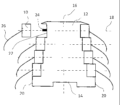
The invention relates to an electrical connection system for connecting a
single-row housing to a
connection element in a connection region of the single-row housing by means
of a plug
contact, thereby permitting connection of the connection element in the
connection region to an
electrical or electronic assembly such as a printed circuit board provided in
the single row
housing, simply and quickly without the use of a tool. Traditional connection
methods for single
row housings with a low width are cumbersome to implement. The invention
solves this
problem with the use of a plug contact.


French Abstract

L'invention a pour objet un système d'assemblage pour relier un boîtier monorangée de connexions (12) à un élément de connexion (10), une zone de connexion (22) étant prévue sur le boîtier monorangée de connexions (12) pour relier l'élément de connexion (10) au boîtier monorangée de connexions (12). Cette zone de connexion (22) est reliée à une carte de circuits imprimés prévue dans le boîtier monorangée de connexions (12). Selon l'invention, l'élément de connexion (10) peut être fixé à la zone de connexion (22) au moyen d'un contact à fiche (24).

Claims

Note: Claims are shown in the official language in which they were submitted.


claims
1. Connection system to connect a single-row housing with a connecting
element, comprising
a connection area on the single-row housing to connect the connecting element
with the single-
row housing, wherein the connection area is connected with an electrical or
electronic assembly
that is provided in the single-row housing, and wherein the connecting element
is configured
to attach to the connection area with a plug contact.
2. Connection system according to claim 1, wherein the plug contact is
designed in a pin shape.
3. Connection system according to claim 1 or 2, wherein the plug contact is
fastened on the
connection area of the single-row housing and the connecting element has an
opening to insert
the plug contact or the plug contact is secured on the connecting element and
wherein the
connection area of the single-row housing has an opening to insert the plug
contact.
4. Connection system according to any one of claims Ito 3, further
comprising a fastening element
configured to secure the connecting element on the single-row housing.
5. Connection system according to any one of claims 1 to 4, wherein the
single-row housing can be
secured on a mounting rail, and wherein the plug contact is mainly provided
with its longitudinal axis
vertical to the longitudinal axis of the mounting rail.
6. Connection system according to any one of claims 1 to 5, wherein more
than one connection
area is provided on the single-row housing, and wherein the more than one
connection areas
are arranged one on top of the other on a side area of the single-row housing.
7. Connection system according to claim 6, wherein at least one connecting
element is configured so
that it can be secured on at least two connection areas that are arranged one
on top of the
other at the same time.
8. Connection system according to any one of claims 1 to 7, wherein the
connection area has an
encoding, especially a mechanical encoding.
9. Connection system according to any one of claims 1 to 8, wherein at
least one first single-row
housing is arranged in series behind a second single-row housing , wherein a
connecting
element is provided which can be fastened in a first connection area of the
first single-row
housing and a second connection area of the second single-row housing at the
same time.
6

Description

Note: Descriptions are shown in the official language in which they were submitted.


CA 02782050 2012-05-25
WO 2011/073342 Al

CONNECTION SYSTEM FOR CONNECTING A SINGLE-ROW HOUSING TO A TERMINAL ELEMENT
The innovation applies to a connection system to connect a single-row housing
with a connecting
element.

For example, a single-row housing is known from DE 10 2006 057 604 Al, whereby
the single-row
housing is designed as an electrical constructional unit for the industrial
control technology for an
arrangement in switch cabinets. The single-row housing can be attached to a
mounting rail, such as a
cap rail. The single-row housing has a significantly greater length than
width, whereby the longitudinal
axis of the single-row housing that is designed along the length of the single-
row housing mainly extends
vertically to the longitudinal axis of the mounting rail. The single-row
housing has multiple levels along
its longitudinal axis, whereby the levels run vertically to the longitudinal
axis. The width of the single-
row housing is thereby designed so that one connection area is designed for
each level to the broadside
of the single-row housing.

The connection area is the area on which a connecting element can be attached
to the single-row
housing. Usually, the connection area has a connection clamp in form of a
screw-type terminal or spring-
loaded terminal, with is used to attach the connection element or a conductor
to the housing.

However, a disadvantage here is that because of the provision of a connecting
clamp in form of a screw-
type terminal or spring loaded terminal the connecting element can only be
attached to the connection
area with a time consuming method utilizing a tool.

Therefore, the innovation is based on the task to provide a connection system
to connect a single-row
housing with a connecting element, which is marked by simplified
manageability.

The solution for the task occurs according to the innovation by utilizing the
characteristics of claim 1.
Advantageous designs of the innovation are indicated in the sub-claims.

The connection system according to the innovation to connect a single-row
housing to a connecting
element has a connection area to connect the connecting element with the
single-row housing that is
provided on the single-row housing, whereby the connection area is connected
to a printed circuit board
that is provided in the housing.

According to the innovation, the connecting element can thereby be attached to
the connection area with
a plug contact.

Because the connecting element can be attached to the connection area with a
plug contact, the
connecting element can be attached to the single-row housing and/or connection
area of the single-row
housing in a short period of time and without having to utilize a tool.

The plug contact is thereby preferably designed as a conductive
electromechanical contact, which is
connected at the initial ending of the electronics that are arranged within
the housing, such as a printed
1


CA 02782050 2012-05-25

circuit board. The plug contact is connected with the connecting element with
an end that is positioned
across from the first end. The connecting element can preferably be connected
with a conductor, which
could be mounted on the connecting element with, for example, a screwed
connection, spring load
connection or direct-push-in-connection. The conductors can thereby no longer
directly attached to the
connecting area of the single-row housing as is provided with the known state-
of-the-art, but with an
additional connecting element, which can simply be attached to the connecting
area of the single-row
housing to establish an electrical contact. The need for cumbersome inserting
of the conductor in the
single-row housing with a very small width at the broadside of the housing and
attachment to
connecting clamp provided there is thereby eliminated.

According to an advantageous design of the innovation, the plug contact is
designed as a pin. For
example, the plug contact can thereby have a circular or rectangular cross-
section. Because the plug
contact is designed as a pin, an especially simple and fast attachment and/or
connection of the
connecting element to the connection area is made possible.

Another preferred provision is that the plug contact is attached to the
connecting area of the single-row
housing and that the connecting element has an opening to plug in the plug
contact or that the plug
contact must be attached to the connecting element and the connecting element
of the single-row
housing has an opening to insert the plug contact. When the connecting element
is attached to the
connecting area, the plug contact can easily be inserted in the corresponding
opening, whereby the
length of the opening preferably mainly corresponds with the length of the
plug contact so that the plug
contact can be inserted completely into the opening. The plug contact is
thereby completely protected
from the environment so that secure contacts are ensured.

Another preferred design is that a fastening element is provided to secure the
connecting element on
the single-row housing. The fastening element must preferably be designed in
form of a snap arm, which
can be latched in a corresponding aperture that is provided for this purpose.
Preferably, the fastening
element is designed so that extraction forces > 15 N are required to be able
to release the connection
with the fastening element. Several fastening elements can thereby be provided
to secure the
connecting element on the single-row housing. For example, the fastening
element can thereby be
arranged on the connecting area of the single-row housing, whereby the
corresponding aperture for this
purpose is then provided on the connecting element. However, a possible
alternative is to arrange the
fastening element on the connecting element, whereby the corresponding
aperture for this purpose is
provided at the connecting area of the single-row housing. The fastening
element makes an additional
securing of the connection of the connecting element on the connecting area
possible.

According to another advantageous design of the innovation, the single-row
housing can be attached
on a mounting rail, whereby the plug contact is mainly provided with its
longitudinal axis vertical to the
longitudinal axis of the mounting rail. The connecting element can thereby be
attached on the side on
the broadside of the single-row housing, which extends across the width of the
single-row housing.
When multiple single-row housings are attached to the mounting rail in
sequence, the connecting
elements can subsequently also easily be attached to the connecting area in
the secured state of the

2


CA 02782050 2012-05-25

single-row housing on the mounting rail without making managing of the
mounting rail more difficult.
The plug direction to connect the single-row housing with the connecting
element is therefore designed
vertical to the longitudinal axis of the mounting rail.

It is preferred to provide more than one connecting area on the single-row
housing whereby the more
than one connecting areas are arranged on top of each other on one of the
broadsides of the housing.
Because multiple connecting areas are arranged on top of each other,
connecting areas may be provided
across the entire length of the single-row housing along the side area,
especially the broadside of the
single-row housing, which results in that several connecting elements can be
connected to the housing
with one plug contact each across the length of the single-row housing on both
of its broadsides.

It is thereby especially preferred that at least one connecting element is
designed so that it can be
attached on at least two connecting areas that are arranged on top of each
other along a broadside of
the single-row housing. The connecting element thereby preferably has two or
more plug contacts or
openings that are arranged on top of each other so that multi-contacting can
occur using a connecting
element.

To make a clear assignment of the connecting element to the corresponding
connecting area possible,
another preferred design of the innovation has an encoding of the connecting
area. For example, the
encoding may occur in form of color coding and/or numerical and/or
alphabetical encoding and/or
mechanical encoding. For example, because of the encoding, a clear assignment
of the corresponding
connecting element to the connecting area that is provided for this purpose
can be ensured after
releasing the connection so that faulty wiring can be prevented.

Furthermore, there is a preferred provision that at least one single-row
housing must be arranged in
series be3hind a second single-row housing whereby a connecting element is
provided, which can be
secured in a first connecting area of the first housing and a second
connecting area of the second
housing at the same time. This makes it possible to contact multiple
connecting areas on different
housings with one connecting element, whereby it is preferred that multiple
connecting areas that are
provided on a level along the cross-axis of the housings of multiple housings
can be contacted with a
connecting element.

The innovation is explained in more detail below in reference to the attached
drawing based on a
preferred design.

The following is shown:

Fig. 1 a connection system according to a design in compliance with the
innovation.

Fig. 1 shows a connection system according to the innovation to connect
multiple connecting elements
with a single-row housing 12. The single-row housing 12 can be secured on its
bottom side 16 to a
mounting rail, which is not shown here, whereby the longitudinal axis 16 of
t6he single-row housing 12

3


CA 02782050 2012-05-25

is designed vertical to the longitudinal axis of the mounting rail. The single-
row housing 12 has multiple
levels 18, which are designed vertical to the longitudinal axis 16 of the
single-row housing. For each level
18, two each connecting elements 10 across from each other are arranged on the
side at the broadsides
20 of the single-row housing 12. Single-row housing 12 hereby means that only
one connecting element
is to be arranged for each level 18 and for each broadside 20. The single-row
housing 12 thereby
preferably has a width along a broadside 20 of 5 to 7 mm.

Fig. 1 shows seven connecting elements 10 connected to the single-row housing
12, whereby a
connecting element 10 is shown released from the single-row housing 12. The
connecting elements 10
can be attached to one connection area 22 provided on each of the single-row
housing 12, whereby the
connection area 22 is provided on the broadside 20 of the housing 10. A pin
shaped plug contact 24 is
provided on connection area 22, to which the connecting element 10 can be
connected to establish a
contact between the connecting element 10 and a printed circuit board that is
arranged in the single-
row housing 12, not shown here, whereby the plug contact 26 and/or the
connection area 22 is
connected with the printed circuit board within the single-row housing 12. The
plug contact 26 is
preferably designed with its longitudinal axis vertical to the longitudinal
axis 16 of the single-row
housing 12 so that the connecting elements 10 can be fastened on the side of
the broadside 20 of the
single-row housing 12 without the use of tools. On the connecting elements 10
themselves, a conductor
26 can in turn preferably be attached with a screwed connection, clamping
force connection or a direct-
push-in connection.

4


CA 02782050 2012-05-25
Reference list

Connecting element 10
Single-row housing 12
Bottom side 14
Longitudinal axis 16
Level 18
Broadside 20
Connection area 22
Plug contact 24
Conductor 26

Representative Drawing
A single figure which represents the drawing illustrating the invention.
Administrative Status

For a clearer understanding of the status of the application/patent presented on this page, the site Disclaimer , as well as the definitions for Patent , Administrative Status , Maintenance Fee  and Payment History  should be consulted.

Administrative Status

Title Date
Forecasted Issue Date 2014-09-09
(86) PCT Filing Date 2010-12-16
(87) PCT Publication Date 2011-06-23
(85) National Entry 2012-05-25
Examination Requested 2012-09-25
(45) Issued 2014-09-09

Abandonment History

There is no abandonment history.

Maintenance Fee

Last Payment of $263.14 was received on 2023-12-05


 Upcoming maintenance fee amounts

Description Date Amount
Next Payment if standard fee 2024-12-16 $347.00
Next Payment if small entity fee 2024-12-16 $125.00

Note : If the full payment has not been received on or before the date indicated, a further fee may be required which may be one of the following

  • the reinstatement fee;
  • the late payment fee; or
  • additional fee to reverse deemed expiry.

Patent fees are adjusted on the 1st of January every year. The amounts above are the current amounts if received by December 31 of the current year.
Please refer to the CIPO Patent Fees web page to see all current fee amounts.

Payment History

Fee Type Anniversary Year Due Date Amount Paid Paid Date
Application Fee $400.00 2012-05-25
Registration of a document - section 124 $100.00 2012-09-24
Request for Examination $800.00 2012-09-25
Maintenance Fee - Application - New Act 2 2012-12-17 $100.00 2012-11-21
Maintenance Fee - Application - New Act 3 2013-12-16 $100.00 2013-11-20
Final Fee $300.00 2014-06-25
Maintenance Fee - Patent - New Act 4 2014-12-16 $100.00 2014-12-08
Maintenance Fee - Patent - New Act 5 2015-12-16 $200.00 2015-11-24
Maintenance Fee - Patent - New Act 6 2016-12-16 $200.00 2016-11-23
Maintenance Fee - Patent - New Act 7 2017-12-18 $200.00 2017-12-11
Maintenance Fee - Patent - New Act 8 2018-12-17 $200.00 2018-12-07
Maintenance Fee - Patent - New Act 9 2019-12-16 $200.00 2019-12-06
Maintenance Fee - Patent - New Act 10 2020-12-16 $250.00 2020-12-02
Maintenance Fee - Patent - New Act 11 2021-12-16 $255.00 2021-12-02
Maintenance Fee - Patent - New Act 12 2022-12-16 $254.49 2022-12-02
Maintenance Fee - Patent - New Act 13 2023-12-18 $263.14 2023-12-05
Owners on Record

Note: Records showing the ownership history in alphabetical order.

Current Owners on Record
PHOENIX CONTACT GMBH & CO. KG
Past Owners on Record
None
Past Owners that do not appear in the "Owners on Record" listing will appear in other documentation within the application.
Documents

To view selected files, please enter reCAPTCHA code :


To view images, click a link in the Document Description column. To download the documents, select one or more checkboxes in the first column and then click the "Download Selected in PDF format (Zip Archive)" or the "Download Selected as Single PDF" button.

List of published and non-published patent-specific documents on the CPD .

If you have any difficulty accessing content, you can call the Client Service Centre at 1-866-997-1936 or send them an e-mail at CIPO Client Service Centre.


Document
Description 
Date
(yyyy-mm-dd) 
Number of pages   Size of Image (KB) 
Abstract 2012-05-25 2 80
Claims 2012-05-25 1 49
Drawings 2012-05-25 1 10
Description 2012-05-25 5 221
Representative Drawing 2012-08-07 1 8
Cover Page 2012-08-07 1 39
Claims 2012-09-25 1 45
Abstract 2014-02-25 1 14
Representative Drawing 2014-08-19 1 9
Cover Page 2014-08-19 1 41
Office Letter 2019-05-07 1 40
PCT 2012-05-25 6 187
Assignment 2012-05-25 4 143
Assignment 2012-09-24 5 125
Prosecution-Amendment 2012-09-25 3 127
Fees 2012-11-21 1 163
Prosecution-Amendment 2013-10-03 2 86
Fees 2013-11-20 1 33
Prosecution-Amendment 2014-02-25 6 249
Correspondence 2014-03-24 9 381
Correspondence 2014-04-11 1 17
Correspondence 2014-06-25 2 79