Note: Descriptions are shown in the official language in which they were submitted.
CA 02782466 2012-05-30
WO 2011/080178 PCT/EP2010/070514
1
AN OVEN DOOR WITH A PLASTIC DOOR COLUMN AND A METHOD FOR
ASSEMBLING SAID PLASTIC DOOR COLUMN
Description
The present invention relates to an oven door with at least one plastic
door column and at least one corresponding door hinge. Further, the
present invention relates to a plastic door column and a method for as-
sembling said plastic door column.
The oven door with the plastic door column is usually arranged at the
oven via a door hinge, wherein one part of the hinge is fixed at the oven
1o and another part of the hinge is fixed in the plastic door column. In par-
ticular, the oven door comprises two plastic door columns and two corre-
sponding hinges.
For fixing the door hinge in the plastic door column on the oven door it
is necessary to use a hook, a slider or a screw. In order to fix and to un-
fix plastic door column and hence the oven door a tool or some special
mounting steps are required. Said special mounting steps are not easy
and require background knowledge.
It is an object of the present invention to provide an oven door with at
least one plastic door column, which can be removed and fixed at the
oven without any tool and special knowledge.
The object of the present invention is achieved by the oven door accord-
ing to claim 1.
According to the present invention the oven door includes at least one
elongated, preferably plastic, door column and at least one correspond-
ing door hinge, wherein:
- the door hinge includes an elongated door part and an oven part,
CA 02782466 2012-05-30
WO 2011/080178 PCT/EP2010/070514
2
- the door column includes an elongated channel for receiving the door
part,
- the door part is detachably mountable or detachably mounted within
the channel,
- a leaf spring for clamping the door part is durably (or: permanently)
fixed within the channel,
- the leaf spring is directly fixed at the door column or door part, and
- a section of the leaf spring is complementary with a corresponding
section of the door part or door column.
The main idea of the present invention is the durably fixed leaf spring for
clamping the door part or door column, wherein the leaf spring is directly
fixed at the door column or door part and the section of the leaf spring is
complementary with the corresponding section of the door part or door
column. The user does not need any tool or any special tricks in order to
remove and fastening the plastic door column and hence the oven door.
Further, the user does not need any fixing elements for fastening the
leaf spring. Since the leaf spring is arranged within the channel, the leaf
spring is not visible.
According to a preferred embodiment of the present invention the leaf
spring and the door part or door column form a snap-in mechanism. The
snap-in mechanism allows an easy handling for the user.
In particular, the leaf spring includes at least one lug directed to the
door part or door column in a mounted state. Accordingly, the door part
or door column includes at least one recess for receiving the lug of the
leaf spring.
Preferably, an outer side of the lug forms an acute angle with a principle
plane of the leaf spring. In contrast, an inner side of the lug forms an
obtuse angle with the principle plane of the leaf spring. The different
CA 02782466 2012-05-30
WO 2011/080178 PCT/EP2010/070514
3
angles of the leaf spring allow different pulling and pushing forces for
removing and assembling, respectively, the oven door.
Further, the snap-in mechanism is formed by the lug of the leaf spring
and the recess.
Preferably the channel extends from one end of the door column at least
mainly and/or approximately parallel to a longitudinal axis of said door
column. A slight inclination could also be advantageous.
1o The present invention relates further to the door column, which is pro-
vided for the oven door as described above.
The object of the present invention is also achieved by the plastic door
column according to claim 9.
The present invention relates also to a method for assembling a, pref-
erably plastic, door column for receiving a door part of a door hinge and
a leaf spring for clamping the door part, wherein the door column is
formed as a single-piece part in particular by plastic coating, the leaf
spring is directly fixed at the door column, and at least one fixing ele-
ment for fastening the leaf spring is formed as an integral part of the
door column.
There are in particular different methods for fixing the leaf spring at the
door column.
A first embodiment of the method is characterized by the steps:
- forming the door column by plastic coating,
- inserting the leaf spring into a channel for receiving the door part,
and
- pressing the leaf spring into the door column.
A second embodiment of the method is characterized by the steps:
CA 02782466 2012-05-30
WO 2011/080178 PCT/EP2010/070514
4
- inserting the leaf spring into a tool design for plastic coating,
- insert moulding the leaf spring, and
- forming the door column by plastic coating.
A third embodiment of the method is characterized by the steps:
- forming the door column by plastic coating,
- inserting the leaf spring into a channel for receiving the door part,
and
- welding the leaf spring with the door column.
A fourth embodiment of the method is characterized by the steps:
- forming the door column by plastic coating,
- inserting the leaf spring into a channel for receiving the door part,
and
- shrinking the leaf spring in the door column, before the door column
has been cooled down.
In all methods described above no additional fixing elements are re-
quired.
Novel and inventive features of the present invention are set forth in the
appended claims.
The present invention will be described in further detail with reference to
the drawings, in which
FIG 1 illustrates a perspective view of a plastic door column with a
door hinge for an oven door according to a preferred embodi-
ment of the present invention,
FIG 2 illustrates a detailed perspective view of the plastic door col-
umn with a leaf spring for the oven door according to the pre-
ferred embodiment of the present invention, and
CA 02782466 2012-05-30
WO 2011/080178 PCT/EP2010/070514
FIG 3 illustrates a detailed sectional view of the plastic door column
with the leaf spring for the oven door according to the pre-
ferred embodiment of the present invention.
5
FIG 1 illustrates a perspective view of a plastic door column 10 with a
door hinge 14 for an oven door according to a preferred embodiment of
the present invention.
1o The oven door comprises preferably two plastic door columns 10 and two
corresponding door hinges 14 and at least one door panel arranged be-
tween the two plastic door columns 10. The door panel and the other
plastic door column with the corresponding door hinge are not shown in
FIG 1.
The door hinge 14 includes an elongated door part 16 and an elongated
oven part 18. In a closed state of the oven door the door part 16 and the
oven part 18 form an angle of about 900. In an open state of the oven
door the door part 16 and the oven part 18 form an angle between about
170 and 180 . The state shown in FIG 1 corresponds with the closed
state of the oven door.
The plastic door column 10 includes a channel 12 for receiving the door
part 16 of the door hinge 14 the channel 12 extending approximately
parallel to a longitudinal axis of the door column 10 from one end of the
column. The plastic door column 10 is detachably mounted at the door
part 16 of the door hinge 14. A leaf spring 20 is durably fixed within the
channel 12 of the plastic door column 10. The leaf spring 20 is provided
for clamping the door part 16 of the door hinge 14.
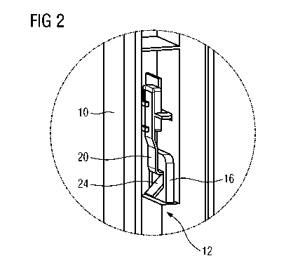
FIG 2 illustrates a detailed perspective view of the plastic door column
10 with the leaf spring 20 for the oven door according to the preferred
CA 02782466 2012-05-30
WO 2011/080178 PCT/EP2010/070514
6
embodiment of the present invention. FIG 2 clarifies the structure of the
leaf spring 20 and the door part 16 of the door hinge 14.
A section of the leaf spring 20 is complementary to a corresponding sec-
tion of the door part 16. The leaf spring 20 includes a lug 24. The door
part 16 includes a recess 26. The lug 24 of the leaf spring 20 and the
recess 26 of the door part 16 form a snap-in mechanism. The recess 26
is marginally bigger than the lug 24.
FIG 3 illustrates a detailed sectional view of the plastic door column 10
1o with the leaf spring 20 for the oven door according to the preferred em-
bodiment of the present invention. FIG 3 clarifies the form of the leaf
spring 20 and its position with the recess 26 of the door part 16 in the
mounted state.
An outer side of the lug 24 forms an acute angle 22 with the principle
plane of the leaf spring 20. In this example the acute angle 22 is more
than about 70 and less than 90 . The acute angle 22 of the lug 22
forms an undercut. An inner side of the lug 24 forms an obtuse angle
with the principle plane of the leaf spring 20. In this example the obtuse
angle is between about 120 and 150 .
The lug 24 of the leaf spring 20 and the recess 26 of the door part 16
allow the user an easy removing and fastening of the oven door. The lug
24 of the leaf spring 20 snaps-in, when the oven door is pushed over the
door parts 16 of the door hinges 14 and fastened. When the oven door is
removed, the user has to spend a bigger force because of the acute an-
gle 22 of the leaf spring 20. Said bigger force prevents an unintended
removing of the door.
3o The leaf spring 20 is directly fixed at the plastic door column 10. No ad-
ditional fixing elements are required. There are several methods for in-
serting and fixing the leaf spring 20 at the plastic door column 10.
CA 02782466 2012-05-30
WO 2011/080178 PCT/EP2010/070514
7
For example, after forming the door column 10 by plastic coating, the
leaf spring 20 is inserted into the channel 12 and the leaf spring 20 is
pressed into the door column 10.
According to another example, after inserting the leaf spring 20 into a
tool design for plastic coating, the leaf spring 20 is insert-moulded and
the door column 10 is formed by plastic coating.
Alternatively, after forming the door column 10 by plastic coating, the
leaf spring 20 is inserted into the channel and the leaf spring 20 is
welded with the door column 10.
Further, after forming the door column 10 by plastic coating, the leaf
spring 20 may be inserted into the channel 12 and the leaf spring 20
shrinks in the door column 10, before said door column 10 has been
cooled down.
The complexity of said methods is very low, since no additional fixing
elements are required.
Although illustrative embodiments of the present invention have been
described herein with reference to the accompanied drawings, it is to be
understood that the present invention is not limited to those precise em-
bodiments, and that various other changes and modifications may be af-
fected therein by one skilled in the art without departing from the scope
or spirit of the invention. All such changes and modifications are in-
tended to be included within the scope of the invention as defined by the
appended claims.
CA 02782466 2012-05-30
WO 2011/080178 PCT/EP2010/070514
8
List of reference numerals
plastic door column
12 channel
14 door hinge
16 door part of the door hinge
18 oven part of the door hinge
leaf spring
22 acute angle
24 lug
26 recess