Note: Descriptions are shown in the official language in which they were submitted.
CA 02782830 2012-07-09
- 1 -
SYSTEM AND METHOD FOR HANGING OBJECTS FROM A ROOF GUTTER
Background and Summary
[0001] The present invention relates generally to removable hangers and,
more
particularly, to a system for hanging objects from the roof gutter of a house
or building.
[0002] Presently, there is no commonly used method of efficiently,
inexpensively and
properly suspending items from the roof gutter of a house or building. A
variety of improvised
materials such as tape, rope/string, commercial hooks, staples, nails and
other materials are often
used to hang a wide variety of items from the roof gutter of a house or
building. All of these
materials tend to detract attention from the items being suspended because of
their unsightly
appearance.
[0003] Specialized hooks are available for hanging holiday lights and the
like on the
exterior of roof gutters. However, these hooks typically can only bear a
limited amount of
weight without deforming the gutter. As such, these hooks are usually not
useful for hanging
heavier items, such as flower pots and bird feeders.
[0004] The present disclosure relates to an easily installed, inexpensive
system for
hanging items from the inside of a roof gutter of a house or building. The
system provides a
hanger that attaches to an exterior of the inner wall of the gutter, thereby
not interfering with the
normal function of the gutter and providing for the hanging of relatively
heavy items from the
gutter, all without deforming the gutter. The system also includes an
installation/removal tool
which is used to install the hanger onto, and to remove the hanger from, a
typical roof gutter. A
variety of items, such as bird feeders, flower pots, flags, banners, sun
screens, insect repellents,
security devices and holiday decorations and lighting, can easily and
conveniently be hung from
the hanger, which is attached to the roof gutter.
[0005] The hanger, in its illustrative configuration, is generally flat
and rectangular in
shape. The hanger is illustratively fabricated or molded from a rigid
material, such as metal or
plastic. An upper end of the hanger may have an angled or bevelled edge to
facilitate insertion
between the inner wall of the gutter and the fascia board of the house or
building. The illustrative
hanger is inserted between an exterior surface of the inner wall of the gutter
and the fascia board
of the house or building, approximately midway between two adjacent gutter
spikes or hangers
CA 02782830 2012-07-09
- 2 -
that secure the gutter to the fascia board of the house or building. A
retainer, illustratively a
hook or lip on the upper end of the hanger, below the bevelled edge, attaches
to the upper edge
of the inner wall of the gutter. In its installed position, the hanger
illustratively extends below
the bottom surface of the gutter and the bottom edge of the fascia board.
Coupling members,
such as a plurality of holes, are illustratively provided near the lower end
of the hanger to
provide for the hanging of a wide variety of items from the gutter.
[0006] The installation/removal tool is illustratively a two-fingered
rigid device, in which
the fingers are separated to define a receiving cavity having a width slightly
greater than the
width of the hanger. Each finger illustratively includes a wedging blade,
tapered on the outside
of each upper end to allow the fingers to be easily inserted between the inner
wall of the gutter
and the fascia board of the house or building. The lower ends of the fingers
are rigidly
connected by a base or handle, in which a notch is provided to allow a
clearance for the easy
insertion of the hanger into the receiving cavity. The installation/removal
tool is illustratively
fabricated or molded from a rigid material such as metal or plastic.
[0007] An illustrative method for installing a roof gutter hanger system
includes the step
of providing a roof gutter, the gutter including an outer wall, an inner wall
substantially parallel
to the outer wall, and a base connecting the outer wall and the inner wall.
The illustrative
method further includes the steps of providing a support surface to which the
inner wall of the
gutter is attached, inserting a gutter hanger intermediate the support surface
and the inner wall of
the gutter, and retaining an upper end of the gutter hanger on the inner wall
of the gutter.
[00081 A method for installing a roof gutter hanger system, including use
of the
installation/removal tool to aid in hanger installation, is also disclosed.
The installation/removal
tool is inserted between the inner wall of the gutter and the fascia board of
the house or building,
approximately midway between two adjacent gutter spikes or hangers that secure
the gutter to
the fascia board of the house or building. The installation/removal tool
provides for a separation
between the gutter and the fascia board for the easy insertion of the hanger.
Once the
installation/removal tool is positioned between the gutter and the fascia
board, the hanger is
inserted between the two fingers of the tool. The hanger is then attached to
the upper edge of the
inner wall of the gutter. The installation/removal tool is next pulled down to
remove it from
between the inner wall of the gutter and the fascia board. To remove the
hanger from the gutter,
CA 02782830 2012-07-09
- 3 -
the installation/removal tool is again inserted, straddling the hanger,
between the gutter and the
fascia board. The hanger is then disconnected from the upper edge of the inner
wall of the gutter
and pulled down for its removal. It should be noted that the installed hanger
is relatively
inconspicuous and therefore may be left installed on the gutter between uses.
[0009] Additional features will become apparent to those skilled in the
art upon
consideration of the following detailed description of the illustrative
embodiments exemplifying
the best mode as presently perceived.
Brief Description of the Drawings
[0010] The embodiments of the invention described herein are not intended
to be
exhaustive or to limit the invention to precise forms disclosed. Rather, the
embodiments selected
for description have been chosen to enable one skilled in the art to practice
the invention.
[0011] Fig. 1 is a perspective view of an illustrative embodiment hanger
coupled to a
roof gutter and supporting an accessory;
[0012] Fig. 2 is a perspective view of the hanger of Fig. 1;
[0013] Fig. 3 is cross-sectional view taken along line A-A of Fig. 1;
[0014] Fig. 4 is a perspective view of an illustrative embodiment
installation/removal
tool;
[0015] Fig. 5 is a perspective view of the installation/removal tool of
Fig. 4 inserted
between the roof gutter and the fascia board;
[0016] Fig. 6 is cross-sectional view taken along line B-B of Fig. 5;
[0017] Fig. 7 is a perspective view of both the hanger and the
installation/removal tool
inserted between the roof gutter and the fascia board, with a partial cut-away
of the gutter for
clarity;
[0018] Fig. 8 is a side elevation view of an illustrative embodiment
hanger being used to
support a bird feeder;
[0019] Fig. 9 is a side elevation view of a pair of illustrative
embodiment hangers being
used to support a flag or banner;
[0020] Fig. 10 is a side elevation view of an illustrative embodiment
hanger being used
to support a flower pot;
CA 02782830 2012-07-09
- 4 -
[0021] Fig. 11 is a side elevation view of a pair of illustrative
embodiment hangers being
used to support a sun screen;
[0022] Fig. 12 is a side elevation view of a pair of illustrative
embodiment hangers being
used to support holiday lights and decorations;
[0023] Fig. 13 is a side elevation view of an illustrative embodiment
hanger being used
to support an intrusion detection device;
[0024] Fig. 14 is a side elevation view of an illustrative embodiment
hanger being used
to support an insect repellent device; and
[0025] Fig. 15 is a side elevation view of an illustrative embodiment of
the hanger being
used to support security light devices.
Detailed Description of the Drawings
[0026] Corresponding reference characters indicate corresponding parts
throughout
several views. The drawings are not necessarily to scale, and certain features
may be
exaggerated to better illustrate and explain the embodiments. The
exemplifications set out herein
illustrate embodiments of the invention in several forms and are not to be
construed as limiting
the scope of the invention in any manner.
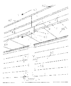
100271 With reference to Fig. 1, an illustrative embodiment roof gutter
hanger system 10
includes a hanger 20 for supporting an accessory, such as a bird feeder 56.
The hanger 20 is
illustratively inserted between a roof gutter 40 and a supporting surface,
such as the fascia board
48 of the supporting structure 12 (e.g., house or building). The roof gutter
40 may be of
conventional design configured to collect and convey water from a roof 44, and
including spaced
apart inner and outer walls 41 and 43 connected by a base 45. Additional
details of the
relationship between the hanger 20 and the gutter 40 and the fascia board 48
are shown, for
example, in Fig. 3. The embodiment of Fig. 1 is further detailed in connection
with Fig. 8, which
shows a conventional downspout 54 coupled to the roof gutter 40 for directing
water collected
from the roof 44 to the ground 58.
[0028] The hanger 20 is further illustrated in Fig. 2. The hanger 20
illustratively includes
a rigid elongated member or body 21 having a plurality of coupling members,
such as holes 26,
that accommodate the hanging of a wide variety of objects. The body 21
includes an extended
CA 02782830 2012-07-09
=
- 5 -
thin section 24 that facilitates insertion of the hanger 20 between the gutter
40 and the fascia
board 48, and for supporting the hanger holes 26 below the gutter 40 and the
fascia board 48. An
upper end of the hanger 20 features a bevelled edge or tapered hanger hook 22
that allows the
body 21 to be easily inserted between the gutter 40 and the fascia board 48. A
retainer, such as
an attachment or lip 28, is supported by the upper end of the hanger 20
opposite the bevelled
edge 22. In other words, the culmination of the bevelled edge 22 provides for
attachment or lip
28 which is configured to connect to an upper edge 47 of the inner wall 41 of
the gutter 40.
[0029] The hanger 20 is illustratively made of a rigid, corrosion and
ultraviolet resistant
material, for example a metal (e.g., aluminium alloy) or polymer (e.g., molded
thermoplastic).
The width of the hanger 20 may vary, depending upon what is being supported,
but must easily
fit between the adjacent attachment spikes or hangers 42 of the gutter 40. A
typical distance
between gutter spikes or hangers 42 is 16 inches. In one illustrative
embodiment, the hanger 20
is 3 inches wide.
[0030] The length of the hanger 20 should be sufficient to allow the
attachment holes 26
to extend below the bottom surfaces of the gutter 40 and the fascia board 48
to facilitate easy
attachment of items to the hanger 20. In one illustrative embodiment, the
hanger 20 is 7.63
inches long. The hanger 20 should have a minimum thickness sufficient to
provide rigidity for
the material chosen. The minimum thickness of an illustrative hanger body 21
formed of an
aluminium alloy is approximately 0.19 inch. As detailed above, the upper end
of the hanger 20
is tapered or bevelled to facilitate its insertion between the gutter 40 and
the fascia board 48.
The bevel is illustratively 30 degrees. The lower end of the taper provides
for a "ledge," "hook"
or attachment lip 28 for attachment to the upper edge 47 of the inner wall 41
of the gutter 40.
The maximum thickness (at the attachment lip 28) of the illustrative hanger 20
is approximately
0.23 inches. The attachment lip 28 should be several times the thickness of
the gutter material to
facilitate attachment to the upper edge 47 of the inner wall 41 of the gutter
40. The illustrative
hanger 20 has three (3) hanger holes 26, approximately 0.25 inches in diameter
for the purpose
of attaching various items that are to be hung.
[0031] Fig. 3 is a cross-sectional view taken along line A-A of Fig. 1,
showing the hanger
20 in the installed position, being attached to the inner wall 41 of the
gutter 40. More
particularly, the body 21 of the hanger 20 is positioned between an exterior
surface of the inner
CA 02782830 2012-07-09
- 6 -
wall 41 of gutter 40 and the fascia board 48, while the attachment lip 28 is
coupled to the upper
edge 47 of the inner wall 41. Fig. 3 also shows the relative positions of the
drip cap 46, the
shingles of roof 44, the soffit 50 and the building siding 52.
[0032] An illustrative embodiment installation/removal tool 30 is shown
in Fig. 4. The
combination of the hanger 20 and the installation/removal tool 30 defines
gutter hanger kit or
system 10. The installation/removal tool 30 illustratively includes a rigid
member that is fully
inserted between the gutter 40 and the fascia board 48, approximately midway
between two
gutter spikes or hangers 42 to facilitate the attachment or removal of the
hanger 20 (where "d"
represents the distance between adjacent gutter spikes or hangers 42, and
"d/2" represents the
approximate midpoint between such adjacent hangers 42). The
installation/removal tool 30
features two vertically extending fingers or wedging blades 36, separated to
define a receiving
chamber 37 having a slightly greater width dimension than the width of the
hanger 20. Angled
edges or bevels 38 on the upper ends of each finger 36 facilitate easy
insertion between the gutter
40 and the fascia board 48. The lower ends of fingers 36 are rigidly attached
to a base or handle
32 that has a notch or clearance opening 34 that allows for the hanger 20 to
be inserted into the
receiving chamber 37. Illustratively, the thickness of each finger 36 is
slightly larger than the
maximum thickness of the hanger 20 (at the tapered or bevelled edge 22).
[0033] The installation/removal tool 30 is illustratively made of a
rigid, corrosion and
ultraviolet resistant material, such as a metal (e.g., welded aluminium alloy)
or a polymer (e.g.,
molded thermoplastic). More particularly, in an illustrative embodiment the
fingers 36 are
welded to handle 32. The fingers 36 of the weldment are inserted between the
gutter 40 and the
fascia board 48 of the building 12. The fingers 36 of the installation/removal
tool are each
illustratively 0.25 inches thick. As detailed above, the end 38 of each finger
36 is tapered or
bevelled (illustratively, by 30 degrees) to facilitate their insertion between
the gutter 40 and the
fascia board 48. The two fingers 36 are separated by a dimension of slightly
greater than the
width of the hanger 20, illustratively by 3.25 inches. Recess or notch 34 is
provided in the
handle 32 to allow for clearance between the fingers 36 when inserting the
hanger 20 between
the gutter 40 and the fascia board 48. The notch 34 is illustratively 0.50
inches deep. As further
detailed herein, the tool 30 may be tapped (e.g., with a hammer), under the
handle 32, to insert
CA 02782830 2012-07-09
- 7 -
the fingers 36 of the tool 30 between the gutter 40 and the fascia board 48,
particularly if the
gutter 40 is tightly installed against the fascia board 48.
[0034] Fig. 5 shows the installation/removal tool 30 in the fully
inserted position,
between the gutter 40 and the fascia board 48. Section B-B, taken from Fig. 5
is shown in Fig. 6.
More particularly, Fig. 6 shows the installation/removal tool 30 fully
inserted between the gutter
40 and the fascia board 48, prior to insertion of the hanger 20.
[0035] Fig. 7 shows the relationship between the hanger 20, the
installation/removal tool
30, the gutter 40 and the fascia board 48 in the process of attaching or
removing the hanger 20
onto or from the gutter 40.
[0036] An illustrative method for attaching the hanger 20 onto the gutter
40, with
reference to Figs. 1-7, is as follows:
[0037] (1) Fully insert the installation/removal tool 30 between the
gutter 40 and the
fascia board 48, approximately midway between two gutter spikes or hangers 42.
A hammer or
similar tool may be used to tap the tool 30 in place if the gutter 40 is
tightly installed against the
fascia board 48.
[0038] (2) Insert the hanger 20 within the receiving chamber 37 between
the fingers 36
of the installation/removal tool 30, and between the gutter 40 and the fascia
board 48.
[0039] (3) Attach the attachment lip 28 on the upper edge 47 of the inner
wall 41 of the
gutter 40.
[0040] (4) Remove the installation/removal tool 30 from between the
gutter 40 and the
fascia board 48.
[0041] An illustrative method for removing the hanger 20 from the gutter
40, with
reference to Figs. 1-7, is as follows:
[0042] (1) Fully insert the installation/removal tool 30 between the
gutter 40 and the
fascia board 48, straddling the hanger 20. A hammer or similar tool may be
used to tap the tool
30 in place if the gutter 40 is tight against the fascia board 48.
[0043] (2) Press the hanger 20 against the fascia board 48 to disengage
the attachment
lip 28 from the upper edge 47 of the inner wall 41.
[0044] (3) Pull the hanger 20 down to remove it from between the gutter
40 and the
fascia board 48.
CA 02782830 2012-07-09
- 8 -
[0045] Once the hanger 20 is installed onto the gutter 40, the hanger 20
is ready for
objects or accessories to be suspended therefrom. Simple attachment devices,
such as hooks 60,
bolts/nuts or similar fasteners are used to attach the item to be hung to one
or more of the hanger
hole(s) 26. It should be noted that some of the embodiments described below
may require more
than one hanger 20. Figs. 8 through 15 show d and d/2, above the gutter 40,
for each hanger 20
to illustrate that the hanger 20 is positioned approximately midway, in
distance, between
adjacent gutter spikes or hangers 42.
[0046] Figs. 8-15 illustrate various accessories that may be supported by
one or more
hangers 20. It should be appreciated that these accessories are only
representative of the wide
variety of accessories that may be used with illustrative hangers 20.
[0047] Figs. 1 and 8 show the hanger 20 being used to hang a bird feeder
56 from the
inner wall 41 of roof gutter 40. A hook 60 is illustratively received within
attachment hole 26 on
lower end of hanger 20. A chain, wire, or cable 61 may connect hook 60 to bird
feeder 56.
[0048] Fig. 9 shows a pair of spaced apart hangers 20 being used to hang
a flag or banner
62 from the inner wall 41 of roof gutter 40. A stabilizer bar 64 extends
between the hangers 20
and supports the flag 62. Tie downs 72 may couple a lower end of the flag 62
to the ground 58.
[0049] Fig. 10 shows the hanger 20 being used to hang a flower pot 68
from the inner
wall 41 of roof gutter 40. Again, hook 60 is received within attachment hole
26 on lower end of
hanger 20. A chain, wire, or cable 61 may connect hook 60 to flower pot 68.
[0050] Fig. 11 shows the hanger(s) 20 being used to hang a sun screen 70
from the inner
wall 41 of roof gutter 40 in front of windows 74. Again, a stabilizer bar 76
extends between the
hangers 20 and supports the sun screen 70. Tie downs 72 may couple a lower end
of the sun
screen 70 to the ground 58.
[0051] Fig. 12 shows the hanger(s) 20 being used to hang decorations 78,
decorative
lights 80 and necessary electrical wiring 82 from the inner wall 41 of roof
gutter 40.
[0052] Fig. 13 shows the hanger 20 being used to support a security
sensor 84 from the
inner wall 41 of roof gutter 40. The security sensor 84 may be a conventional
motion sensing
device.
[0053] Fig. 14 shows the hanger 20 being used to support an insect
repellent 86 from the
inner wall 41 of roof gutter 40. The insect repellent 86 may be a conventional
electric insect
CA 02782830 2014-06-13
,
- 9 -
repelling device, for example a device dispensing an airborne repellent or
generating an electric
charge.
[0054] Fig. 15 shows the hanger 20 being used to support security
lighting 88 from the
inner wall 41 of roof gutter 40.
[0055] The scope of the claims should not be limited by the preferred
embodiments set
forth in the examples, but should be given the broadest interpretation
consistent with the
description as a whole.