Note: Descriptions are shown in the official language in which they were submitted.
CA 02783353 2012-07-16
TITLE
[0001] Banding strap
FIELD
[0002] This relates to a banding strap, such as a strap that is used to
band items.
BACKGROUND
[0003] Banding or tie straps are used in many different areas to restrain
items, or to keep
items together. Some examples of situations where banding is used include:
storing cords
and hoses; grouping elongate objects such as hockey sticks, golf clubs, etc.;
installing hoses,
cables or cords along scaffolding or railings; and other areas. This banding
may be done
using a zip tie, tape, bungee cords, etc. An example of a cargo strap can be
found in U.S.
patent no. 7,805,816 (Thorne, III et al.) entitled "Cargo Strap". Another
example can be
found in U.S. patent no. 5,673,464.
SUMMARY
[0004] There is provided a banding strap that has an elongate member made
from a
flexible, resilient material. The elongate member has a length, a diameter, a
stop section and a
seat section. The stop section has one or more stops spaced along the elongate
member. Each
stop has a diameter that is greater than the diameter of the elongate member.
The seat section
defines a seat that faces the stop section along the elongate member and a gap
above the seat
relative to the elongate member that is sized to receive the elongate member.
The gap has a
width that is less than the diameter of the one or more stops. The seat
defines a cavity that,
when a stop is received, restrains one of the one or more stops against a
force applied along
the length of the elongate member. The stop section engages the seat section
by bending the
elongate member such that the elongate member overlaps itself at the seat
section.
[0005] In an aspect, there are a plurality of stops spaced along the stop
section which
allows a single banding strap to be used for strapping together bundles of
items with different
diameters.
[0006] In an aspect, each stop is a spherical shape and the seat has a
portion of a spherical
cavity.
CA 02783353 2012-07-16
2
[0007] In an aspect, the seat section may be removably attached to the
elongate member
or may be integrally formed with the elongate member.
[0008] In an aspect, the seat section is made from the same material as the
stop section of
the banding strap.
[0009] In an aspect, the gap is defined by two protrusions formed from a
resilient
material.
[0010] In an aspect, the cavity has a radial portion that receives the
stop in a radial
direction relative to the elongate member and an axial portion that receives
the stop in an axial
direction relative to the elongate member.
[0011] In an aspect, the radial portion may be recessed within the diameter
of the
elongate member.
[0012] In an aspect, the elongate member also has a handle section
adjacent to the seat
section such that the seat section is between the handle section and the stop
section.
[0013] In an aspect, the gap is sized to receive the elongate member in a
stretched state
such that the diameter of the elongate member is reduced.
[0014] There is provided, in combination, an elongate member and a seat
section. The
elongate member is made from a flexible, resilient material and has a
plurality of stops spaced
along the elongate member. Each stop has a diameter that is greater than a
diameter of the
elongate member. The seat section has an attachment with a first cavity that
receives the
elongate member. The seat section also has a seat with a second cavity that is
sized to receive
one of the stops and a gap above the seat relative to the elongate member that
is sized to
receive the elongate member and is less than the diameter of the one or more
stops.
CA 02783353 2012-07-16
3
[0015] In an aspect, the seat section also has a locking member
that locks the attachment
onto the elongate member.
[0016] In an aspect, the locking member may be integrally formed
with the attachment or
the locking member can be separate and distinct from the seat section.
BRIEF DESCRIPTION OF THE DRAWINGS
[0017] These and other features will become more apparent from the
following
description in which reference is made to the appended drawings, the drawings
are for the
purpose of illustration only and are not intended to be in any way limiting,
wherein:
FIG. 1 is a top perspective view of a banding strap.
FIG. 2 is a bottom perspective view of the banding strap shown in FIG. 1.
FIG. 3 is a top plan view of the banding strap shown in FIG. 1.
FIG. 4 is a side elevation view in section of the seat portion of the banding
strap
shown in FIG. 1.
FIG. 5 is a perspective view of the banding strap of FIG. 1 in a connected
orientation.
FIG. 6 is a top plan view of the banding strap of FIG. 1 in the connected
' orientation.
FIG. 7 is a perspective view of the banding strap shown in FIG. 1 banding
items
together.
FIG. 8 is a side perspective view of a banding strap with a removable seat
section.
FIG. 9 is a bottom perspective view of the banding strap with a removable seat
section shown in FIG. 8.
FIG. 10 is a top plan view of the banding strap with a removable seat section
shown in FIG. 8.
FIG. 11 is a top perspective view of the banding strap with a removable seat
section shown in FIG. 8.
FIG. 12 is a perspective view of a banding strap on a reel.
FIG. 13 is a perspective view of a banding strap with a variation of a seat
section.
FIG. 14 is a side elevation view of the banding strap with a variation of a
seat
CA 02783353 2012-07-16
4
section shown in FIG. 13.
DETAILED DESCRIPTION
[0018] A banding strap generally identified by reference numeral 10, will
now be
described with reference to FIG. 1 through 14.
Structure and Relationship of Parts:
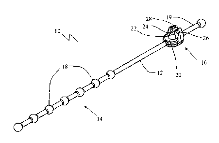
[0019] Referring to FIG. 1 and 2, banding strap 10 has an elongate member
12 made
from a flexible, resilient material. As used herein, the terms "band" or
"banding" are used to
include any situation where strap 10 is wrapped around one or more items, and
may be
considered equivalent to bundling, bunching, baling, or otherwise securing or
packaging
multiple items together or securing single items. Preferably, elongate member
12 is made
from rubber or a material with properties similar to rubber. The actual
material will depend
on the intended uses of the product, the size, etc. Elongate member 12 is
shown as as being
relatively thin and narrow and having a round cross-section. Elongate member
12 may also
be designed with other cross-sections, such as a rectangular, oval,
rectangular with rounded
edges, etc. and may be thin or tape-like. The actual design of elongate member
12 will
depend on the intended use and the preferences of the user. Elongate member 12
is designed
to have a two part connector with a stop section 14 and a seat section 16.
Stop section 14 is
shown as having a number of stops 18 spaced along elongate member 12. This
allows the
size of banding strap 10 to be adjusted according to what is being secured,
although a single
stop 18 may be used if the size is known. Each stop 18 protrudes radially from
elongate
member 12. In other words, each stop 18 has a diameter that is greater than
the diameter of
elongate member 12. As will be described below, stops 18 engage seat section
16 and the
shape of stop 18 must be capable of being engaged and held by seat section 16.
Accordingly,
while stops 18 are shown as being generally spherical in shape, they may take
other sizes and
shapes as well, such as rectangular, conical, pyramidal, etc. in various
orientations, as will be
recognized by those skilled in the art.
[0020] Elongate member 12 may also have an additional handle 19 that
extends out from
seat section 16 opposite stop section 14. This is intended to make banding
strap 10 easier to
CA 02783353 2012-07-16
handle while being engaged and disengaged. It will be understood that handle
19 may take
various forms, although it is preferred that handle 19 be small enough that it
does not become
an obstruction as well as an aid.
5 [0021] Seat section 16 is designed to be complementary to stops 18
in stop section 14 in
order to receive and retain stops 18. As shown in FIG. 3, seat section 16 is
integrally formed
with elongate member 12 and is made from the same material. It will be
understood that seat
section 16 may be made from a different material that is molded into elongate
member 12, or
may be a separate component altogether, such as is shown in FIG. 8. Even if
seat section 16
is made as a separate component, it may still be made from the same or
different material than
elongate member 12. The variation shown in FIG. 8¨ 12 will be discussed below.
[0022] Referring to FIG. 3, seat section 16 defines a seat 20 that is
oriented toward stop
section 14 along elongate member 12. Seat 20 is preferably shaped to snugly
receive one of
stops 18, although it may have a different shape than stops 18, as long as it
is able to retain
stops 18 under normal operating conditions. Referring to FIG. 4, seat 20 is
depicted as
having a radially depressed portion 22 that extends downward into elongate
member 12. Seat
also includes an axially depressed portion 24 that is above radially depressed
portion 22
relative to elongate member 12. As can be seen in FIG. 5 and 6, when stop 18
is engaged
20 within seat 20, stop 18 becomes seated within the radially and axially
depressed portions 22
and 24, which grip stop 18 under normal operating conditions. Radially
depressed portion 24
allows elongate member 12 to lie closer to itself, or in other words to allow
banding strap 10
to lie flatter in the engaged position, as can be seen in FIG. S. It also
increases the surface
area that engages stop 18, which increases the friction and hence the
engagement. However,
stop 18 is primarily held in place by axially depressed portion 24. Referring
again to FIG. 3
and 4, axially depressed portion 24 is formed by upstanding members 26 that
curve over at
the top to form axially depressed portion 24. When stop 18 is engaged within
seat 20, this
holds stop 18 in place against forces applied along elongate member 12.
[0023] In order to allow stops 18 to be engaged within seat 20, seat
section 16 has a gap
28 that is above seat 20 relative to elongate member 12. Gap 28 has a width
that is sized to
CA 02783353 2012-07-16
6
receive elongate member 12, but that is less than the diameter of stops 18.
When seat section
16 is made from a resilient material, it may be desired to make gap 28 very
close to the
diameter of elongate member 12 or even narrower than elongate member 12 in
order to
provide additional strength to seat section 16. In this design, it is intended
that elongate
member 12 will pass through gap 28 when elongate member 12 is stretched around
an object,
which will generally be necessary when banding an article or multiple articles
together. As
elongate member 12 is stretched, it also narrows. In addition, if seat section
16 is made from
a resilient material, upstanding members 26 may spread apart slightly as
elongate member 12
is pulled through gap 28, allowing stop 18 to become seated within seat 20. In
this manner
the holding force on stop 18 may be increased. Preferably, gap 28 is parallel
to the direction
of elongate member 12, which makes it easier to insert when being wrapped
around an object
or objects to be bound, as elongate member 12 generally ends up being
substantially parallel
to itself when engaged, as can be seen in FIG. 6 and 7. It will be understood
that gap 28 need
not be parallel or extend directly upward from seat portion 16 as shown, and
could be at an
angle, such as by providing a side or angled entry into seat 20.
[0024] Referring to FIG. 7, banding strap 10 is preferably used by
holding seat portion
16 adjacent to an article or articles to be bound, and wrapping stop portion
14 around the
articles. As stop portion 14 approaches seat portion 16, tension is applied to
elongate member
12, causing it to stretch until a stop 18 has been pulled past stop portion
14. Elongate member
12 is then lowered through gap 28 and the tension on elongate member 12 is
released until
stop 18 drops into seat 20. The angle of the elongate member 12 and the
tension in elongate
member 12 keeps stop 18 pressed down and into seat 20 to hold it in place. It
has been found
that it is generally easier to engage stop 18 into seat 20 when elongate
member 12 is in
tension and wrapped around one or more articles to be bound. Banding strap 10
is preferably
designed as a light-duty attachment, and may be designed to withstand, for
example, up to
about 50 lb or up to 100 lb of pressure before releasing. The amount of force
that banding
strap 10 is able to withstand may be varied depending on the design, and also
by providing a
locking mechanism, as will be described below. The rating of banding strap 10
will depend
on the design and the preferences of the user. Banding strap 10 may be
designed for general
purpose binding where great forces are not required to keep objects bound, but
merely
CA 02783353 2012-07-16
7
sufficient force to keep elongate objects together. Examples of household
situations include
binding a patio umbrella in the closed position, securing a coiled hose or
electrical cord,
securing long rods, sticks, boards, hockey sticks, etc. Banding straps 10 may
also be used in
industrial situations, such as to mount electrical cables to scaffolding,
temporarily binding
cable or wires together along the ground, etc. Banding strap 10 may also be
used in garments,
for medical or first aid purposes, etc. Other uses will be recognized by those
skilled in the art.
Each intended use may have different requirements and therefore may differ
from the
examples depicted in the attached drawings.
[0025] If a longer banding strap 10 is required, two or more may be 'daisy-
chained'
together by engaging a stop 18 on one banding strap 10 in the seat 20 of an
adjacent banding
strap. Banding strap 10 may be released by pulling up op the portion of
elongate member 12
that extends past seat portion 16. If seat portion 16 is made from a resilient
material, the
upward force generally causes gap 28 to increase, allowing elongate member 12
to pass
through, such that banding strap 10 may be released by a simple upward tug. A
preferred
design of banding strap 10 permits it to be released with one hand, or in
other words, without
having to apply opposing forces on both stop portion 14 and seat portion 16.
If some or all of
seat portion 16, is made from a rigid material, or if stops 18 are more deeply
received within
seat 20, it may be necessary to pull elongate member 12 as well to withdraw
stop 18 from
cavity 20. As shown, stop 18 is received within seat 20 only to the point that
seat 20 is still
engaged by an inclined surface. This makes it easier to pull out of seat 20.
Generally
speaking, banding strap 10 should be installed with some portion of elongate
member 12
extending past seat portion 16 to act as a handle. Alternatively, another
handle portion may
be formed at the end of elongate member 12. This allows stops 18 to be pulled
past seat 20
and dropped into place, as well as allowing the upward, releasing force to be
applied. Once
released, banding strap 10 can be reused.
[0026] It will also be understood that, rather than wrapping elongate
member 12 in a
circle as shown in FIG. 5 ¨7, it may also be folded back onto itself as shown
in FIG. 13 and
14. However, as there is no tension holding stop 18 in seat 20, this will
generally not have the
same binding force as in the configuration shown in FIG. 5 ¨ 7. Instead, this
is particularly
CA 02783353 2012-07-16
8
useful if an additional locking element 30 is applied to seat portion 16, as
shown in FIG. 13
and 14. As depicted, locking element 30 is a ring that is installed above
elongate member 12
and stop 18 when received by cavity 20. This prevents stop 18 from being
withdrawn and
accidentally releasing binding strap 10. It may also increase the structural
strength of seat
portion 16, particularly if it is made from a resilient material. In other
circumstances, some
part of elongate member 12 may be secured to a wall or item as a permanent
attachment.
[0027] In the depicted example, locking element 30 is part of a seat
portion 32 that is
designed to be separate and distinct from elongate member 12 and installed at
a desired
position. As such, in addition to locking binding strap in the engaged
position, it also helps
lock seat portion 32 to elongate member 12. Referring to FIG. 8 and 9,
removable seat
portion 32 has a hinged bottom 34 with a cavity 36 sized to receive elongate
member 12 that
allows it to be installed on elongate member 12. Referring to FIG. 10,
removable seat portion
32 also has an engagement profile 38, such that it snaps together in the
closed position.
Referring to FIG. 10 and 11, in the depicted example, removable seat portion
32 is installed
between stops 18 along elongate member 12, such that it is prevented from
sliding along the
length of elongate member 12.
[0028] It will be understood that removable seat portion 32 may take
different forms. For
example, seat portion 32 may be designed to engage a stop 18 to increase the
stability on
elongate member 12. In another example, seat portion 32 may have an open
bottom rather
than hinged bottom 34, such that it is installed by pressing it down onto
elongate member 12.
There are various other designs that may involve clips or ties that may also
be used to install
seat portion 32 on elongate member 12.
[0029] One benefit of using removable seat portion 32 is that the length
of elongate
member 12 may be custom designed for a particular situation. Referring to FIG.
12, a
continuous length of elongate member 12 may be stored on a reel 42. A selected
length of
elongate member 12 is selected by pulling it off reel 42, and cutting elongate
member 12 to
the desired length. Referring to FIG. 9 and 11, seat portion 32 is attached as
described above.
Referring to FIG. 13 and 14, once stop 18 engages seat 20, a locking member 30
may be
installed. Another benefit of using removable seat portion 32 is that the
orientation may
CA 02783353 2012-07-16
9
change, such that elongate member 12 may be folded over as shown in FIG. 13
and 14, or it
may be looped as shown in FIG. 5 ¨ 7. In either situation, seat 20 will be
properly oriented to
receive stop 18.
[0030] As shown in FIG. 11 and 13, locking member 30 engages a recess 40 in
seat
portion 32. This helps keep seat portion 32 together, and also helps secure
elongate member
12 or stop 18 within seat portion 32. Locking member 30 is shown as a ring,
and may be
designed to be removable, such as by using looser tolerances, an elastic
material, rounded
edges, etc. Alternatively, locking member 30 may be designed to be permanent.
In this
context "permanent" means not removable without breaking locking member 30.
For
example, locking member 30 may be designed with a profile that allows it to be
slid over top
of seat portion 32 to engage recess 40, but that does not permit it to be
removed. It may also
be made with tighter tolerances, with sharp edges, from a more rigid material,
etc.
[0031] While locking member 30 is shown in the context of removable seat
portion 32, it
may also be used on attached seat portion 16 shown and discussed previously.
In this
situation, locking member 30 would not be used to secure seat portion 16 onto
elongate
member 12, but rather to secure it in the engaged position. Again, this may be
done in a
removable or permanent way, depending on the preferences of the user. This
will generally
increase the amount of force that can be withstood, and will also reduce the
likelihood of an
accidental release, such as by accidentally brushing elongate member 12 when
engaged. The
permanent attachment may be used to make banding strap 10 tamper resistant, as
locking
member 30 may not be removed except by being broken or cut.
[0032] In this patent document, the word "comprising" is used in its non-
limiting sense to
mean that items following the word are included, but items not specifically
mentioned are not
excluded. A reference to an element by the indefinite article "a" does not
exclude the
possibility that more than one of the element is present, unless the context
clearly requires that
there be one and only one of the elements.
[0033] The following claims are to be understood to include what is
specifically illustrated
CA 02783353 2012-07-16
and described above, what is conceptually equivalent, and what can be
obviously substituted.
The scope of the claims should not be limited by the preferred embodiments set
forth in the
examples, but should be given the broadest interpretation consistent with the
description as a
whole.
5