Language selection

Search

Patent 2783364 Summary

Third-party information liability

Some of the information on this Web page has been provided by external sources. The Government of Canada is not responsible for the accuracy, reliability or currency of the information supplied by external sources. Users wishing to rely upon this information should consult directly with the source of the information. Content provided by external sources is not subject to official languages, privacy and accessibility requirements.

Claims and Abstract availability

Any discrepancies in the text and image of the Claims and Abstract are due to differing posting times. Text of the Claims and Abstract are posted:

  • At the time the application is open to public inspection;
  • At the time of issue of the patent (grant).
(12) Patent Application: (11) CA 2783364
(54) English Title: AMMUNITION MAGAZINE
(54) French Title: CARTOUCHE DE MUNITIONS
Status: Deemed Abandoned and Beyond the Period of Reinstatement - Pending Response to Notice of Disregarded Communication
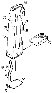
Bibliographic Data
(51) International Patent Classification (IPC):
  • F41C 27/00 (2006.01)
  • F41A 9/61 (2006.01)
  • F41A 35/00 (2006.01)
  • F41C 23/22 (2006.01)
(72) Inventors :
  • PLATANIOTIS, NICHOLAS ANTHONY (United States of America)
  • TRUMAN, RICHARD CLINTON (United States of America)
(73) Owners :
  • NICHOLAS ANTHONY PLATANIOTIS
  • RICHARD CLINTON TRUMAN
(71) Applicants :
  • NICHOLAS ANTHONY PLATANIOTIS (United States of America)
  • RICHARD CLINTON TRUMAN (United States of America)
(74) Agent: MACRAE & CO.
(74) Associate agent:
(45) Issued:
(22) Filed Date: 2012-07-18
(41) Open to Public Inspection: 2013-01-18
Examination requested: 2017-07-18
Availability of licence: N/A
Dedicated to the Public: N/A
(25) Language of filing: English

Patent Cooperation Treaty (PCT): No

(30) Application Priority Data:
Application No. Country/Territory Date
13/551,701 (United States of America) 2012-07-18
61/508,993 (United States of America) 2011-07-18

Abstracts

English Abstract


A firearm includes a barrel having first and second ends, and is adapted to
fire a round of ammunition from the second end. A handgrip is operatively
coupled to
and extending in a downward direction relative to the barrel. An ammunition
magazine
is removably received within the handgrip. The magazine includes a front, a
rear, and a
pair of opposed side surfaces extending between the front and rear. A clip
member
includes at least an arm portion extending along the rear of the magazine. The
arm
portion of the clip member is adapted to allow the ammunition magazine to be
temporarily attached to an object while outside of the magazine.


Claims

Note: Claims are shown in the official language in which they were submitted.

1. A firearm, comprising:
a barrel having first and second ends, and adapted to fire a round of
ammunition from the second end,
a handgrip operatively coupled to and extending in a downward direction
relative to the barrel, the handgrip including a cavity with a lower end
defining an
opening,
an ammunition magazine removably received within the cavity of the
handgrip by insertion of the magazine through the opening, the magazine having
a
front, a rear, and a pair of opposed side surfaces extending between the front
and rear,
and
a clip member having at least an arm portion extending along the rear of
the magazine, the arm portion of the clip member adapted to allow the
ammunition
magazine to be temporarily attached to an object while the magazine is outside
of the
cavity.
2. The firearm of claim 1, wherein the firearm further comprises a handgun.
3. The firearm of claim 2, wherein the handgun further comprises a 9mm
handgun.
4. The firearm of claim 3, wherein the magazine is received fully in the
cavity
of the handgrip such that the arm portion of the clip member is at least
substantially fully
concealed within the handgrip.
5. The firearm of claim 1, wherein the magazine is received fully in the
cavity
of the handgrip such that the arm portion of the clip member is at least
substantially fully
concealed within the handgrip.
6. The firearm of claim 1, wherein the clip member further comprises a spring
clip.
-6-

7. The firearm of claim 1, wherein the spring clip is formed from metal.
8. The firearm of claim 1, wherein the magazine further includes a bottom,
and the spring clip is formed from a metallic plate having a base plate
secured to the
bottom of the magazine and the arm portion extending upwardly along a rear
interior
surface of the cavity.
9. An ammunition magazine adapted to be removably received within a
handgrip of a firearm, the magazine comprising:
a front, a rear, and a pair of opposed side surfaces extending between the
front and rear, and
a clip member having at least an arm portion extending along the rear of
the magazine, the arm portion adapted to allow the ammunition magazine to be
temporarily attached to an object while outside of a cavity of the handgrip.
10. The ammunition magazine of claim 9, wherein the magazine further
comprises a handgun magazine.
11. The ammunition magazine of claim 10, wherein the magazine further
comprises a 9mm handgun magazine.
12. The magazine of claim 11, wherein the magazine is configured to be
received fully in the cavity of the handgrip such that the arm portion is at
least
substantially fully concealed within the handgrip.
13. The magazine of claim 9, wherein the magazine is configured to be
received fully in the cavity of the handgrip such that the arm portion is at
least
substantially fully concealed within the handgrip.
-7-

14. The magazine of claim 9, wherein the clip member further comprises a
spring clip.
15. The magazine of claim 9, wherein the spring clip is formed from metal.
16. The magazine of claim 9, wherein the magazine further includes a bottom,
and the spring clip is formed from a metallic plate having a base plate
secured to the
bottom of the magazine with the arm portion extending upwardly along the rear
of the
magazine.
17. A firearm, comprising:
a barrel having first and second ends, and adapted to fire a round of
ammunition from the second end,
a handgrip operatively coupled to and extending in a downward direction
relative to the barrel, the handgrip including a cavity with a lower end
defining an
opening,
an ammunition magazine removably received within the cavity of the
handgrip by insertion of the magazine through the opening, the magazine having
a
front, a rear, and a pair of opposed side surfaces extending between the front
and rear,
and
a clip member having at least an arm portion extending along one of the
front, rear or side surfaces of the magazine,
wherein the magazine is received fully in the cavity of the handgrip such
that the arm portion of the clip member is at least substantially fully
concealed within the
handgrip, and the clip member is adapted to allow the ammunition magazine to
be
temporarily attached to an object while the magazine is outside of the cavity.
18. A method of using a firearm, wherein the firearm comprises a barrel
having first and second ends, and adapted to fire a round of ammunition from
the
second end, a handgrip operatively coupled to and extending in a downward
direction
relative to the barrel, the handgrip including a cavity with a lower end
defining an
-8-

opening, an ammunition magazine removably received within the cavity, and a
clip
member having at least an arm portion extending along the magazine, the method
comprising:
temporarily securing the magazine outside of the firearm by clipping the
magazine to an object by securing the object between the clip member and the
magazine,
unclipping the magazine from the object, and
inserting the magazine through the opening and into the cavity of the
handgrip such that the arm portion is at least substantially fully concealed
within the
handgrip.
-9-

Description

Note: Descriptions are shown in the official language in which they were submitted.


CA 02783364 2012-07-18
AMMUNITION MAGAZINE
Cross-Reference to Related Application
[0001] This application claims the priority of U.S. Provisional Patent
Application
Serial No. 61/508,993, filed on July 18, 2011 (pending), the disclosure of
which is
incorporated by reference herein.
Technical Field
[0002] The invention generally relates to ammunition magazines for firearms
and,
more particularly, ammunition magazines for semi-automatic pistols and manners
of
carrying such magazines while they are separated from the firearm.
Background
[0003] Ammunition magazines, for use with automatic or semi-automatic
weapons such as pistols, are generally made in the form of elongate tubes or
containers
for holding the ammunition in a stacked condition. The magazine is inserted
into the
opening of a cavity or chamber in the firearm by pushing the magazine upwardly
through the opening and locking it into place. The bottom surface of the
magazine, at
least in the case of a pistol, becomes the bottom surface of the pistol grip.
[0004] The user of an automatic or semi-automatic weapon often finds it
necessary or desirable to find a way to carry one or more spare ammunition
magazines.
Various manners have been used in the past for accomplishing this task,
including the
use of special apparel with pockets, belts or holsters, or other means.
Magazines with
integrated clips have also been proposed but have various drawbacks limiting
their
usefulness.
[0005] For these and other reasons, there is a need for improvements in the
area
of ammunition magazines having clip members for easily carrying one or more
magazines on the user, or on an item carried by the user, or even on another
object
such as for longer term storage.
-1-

CA 02783364 2012-07-18
Summary
[0006] The invention, in one illustrative embodiment, generally comprises a
firearm including a barrel having first and second ends, and adapted to fire a
round of
ammunition from the second end. A handgrip is operatively coupled to and
extends in a
downward direction relative to the barrel. An ammunition magazine is removably
received within a cavity of the handgrip by inserting the magazine into an
opening at a
lower end of the cavity. The magazine includes a front, a rear, and a pair of
opposed
side surfaces extending between the front and rear. A clip member includes at
least an
arm portion extending along the rear of the magazine, and the arm portion of
the clip
member is adapted to allow the ammunition magazine to be temporarily attached
to an
object while the magazine is outside of the cavity. The object may, for
example, be a
pocket in a piece of apparel worn by the user, or may be any other suitable
object such
as a belt or other item worn by or carried by a user of the firearm. In other
situations,
such as for longer term storage, the object might not be associated directly
with the
user.
[0007] In other embodiments, the clip member may be attached along another
surface of the magazine and is at least substantially fully concealed within
the cavity of
the handgrip when the magazine is fully inserted during use.
[0008] The firearm may take any of various forms, but the preferred form is a
handgun, such as but not limited to a 9mm semi-automatic handgun. The magazine
is
received fully in the cavity of the handgrip such that the arm portion of the
clip member
is at least substantially fully concealed within the handgrip. This maintains
the
aesthetics of the firearm, ensures that the clip member does not interfere
with handling
of the weapon, and helps prevent damage to the clip member. In one
illustrative form,
the clip member further comprises a spring clip, which may be made of metal,
such as
by being stamped from a metal plate. The magazine further includes a bottom,
and the
spring clip is formed with a base plate configured to be secured to the bottom
of the
magazine and with the arm portion adapted to extend upwardly along the rear of
the
magazine and along a corresponding rear, interior surface of the cavity when
the
magazine is inserted into the handgrip.
[0009] In other embodiments, the invention comprises an ammunition magazine
-2-

CA 02783364 2012-07-18
as described herein, and a method of using a firearm as described herein.
Generally,
the method includes:
temporarily securing the magazine outside of the firearm by clipping the
magazine to an object by securing the object between the clip member and the
magazine,
unclipping the magazine from the object, and
inserting the magazine into a cavity of the handgrip such that the arm
portion is at least substantially fully concealed within the handgrip.
[0010] Various additional advantages and features will become more readily
apparent to those of ordinary skill in the art upon review of the following
detailed
description of the illustrative embodiments taken in conjunction with the
accompanying
drawings.
Brief Description of the Drawings
[0011] Fig. 1 is a perspective view of a clip member constructed in accordance
with an illustrative embodiment of the invention.
[0012] Fig. 2 is a side elevation view of the clip member shown in Fig. 1.
[0013] Fig. 3 is a disassembled perspective view of a pistol ammunition
magazine being assembled with the clip member of Fig. 1.
[0014] Fig. 4 is a disassembled perspective view of the assembled pistol
ammunition magazine of Fig. 3 being assembled with a pistol grip.
[0015] Fig. 5 is a perspective view of a pistol, shown partially in dash-dot
lines for
illustrative purposes only, assembled with the magazine of Fig. 4.
[0016] Fig. 6 is a side elevation view of the clip member of Fig. 1, shown in
dash-
dot lines, and temporarily attaching the magazine to an object such as a piece
of fabric
which forms a pocket in an item of apparel.
Detailed Description
[0017] Figs. 1 and 2 illustrate a clip member 10 constructed in accordance
with
an illustrative and non-limiting embodiment of the invention. This clip member
10
includes a base plate 12 and an arm portion 14 extending from the base plate
12. The
-3-

CA 02783364 2012-07-18
arm portion 14 provides a spring clip mechanism as will be further described
below.
The arm portion may, for example, be about 2 1/2" in length. The clip member
10, in this
embodiment, may be easily formed by a metal stamping operation in which the
entire
integral plate structure of the clip member 10 is first stamped in a flat
condition, and
then the angle 15 of the clip member 10 and the curved bend 16 are then formed
by
additional forming machinery. The clip member 10 is preferably formed from a
metal,
such as a spring-type metal, e.g., stainless steel.
[0018] As further shown in Figs. 3 and 4, the clip member 10 is assembled and
secured to an ammunition magazine 20 which, in turn, is removably received
within the
cavity 22 (Fig. 5) of a handgrip 24 associated with a semi-automatic pistol 26
(Fig. 5).
While a 9mm semi-automatic pistol 26, such as a Glock brand pistol, is shown
in the
drawings, it will be understood that the embodiments of the present invention
may be
used with any firearm that utilizes an ammunition magazine, such as semi-
automatic or
automatic weapons of other types as well. The ammunition magazine 20 includes
a
front 30, a rear 32, and a pair of opposite surfaces 34, 36 extending between
the front
30 and rear 32. The ammunition magazine 20 further includes a suitable cap or
end
plate 40 defining a bottom surface of the magazine 20 and which secures the
base plate
12 of the clip member 10 to the magazine 20 as shown in Figs. 3 and 4. It will
be
understood that other securing methods may be used instead, or the clip arm
portion 14
may be more directly secured or manufactured as part of the magazine 20. The
base
plate 12 may include a hole (not shown) for location purposes if desired.
[0019] Referring now to Figs. 3, 4 and 5, the magazine 20 is received fully in
the
cavity 22 of the handgrip 24, such as the pistol grip of a 9mm semi-automatic
pistol 26,
such that the arm portion 14 of the clip member 10 is at least substantially
fully
concealed within the handgrip 24 (Fig. 5). Therefore, when the firearm 26 is
in use, with
the magazine 20 inserted as shown in Fig. 5, the clip member 10 is concealed
for
aesthetic value, and is not in a position to interfere with handling of the
firearm 26, or in
a position to be damaged during handling of the firearm 26. As further shown
in Fig. 5,
the firearm 26 generally includes a barrel 50 having first and second ends 52,
54 and is
adapted to fire a round ammunition 56 (Fig. 4) from the magazine 20 out
through the
second end 54. In the case of a pistol 26, as shown, the handgrip 24 is
coupled to the
-4-

CA 02783364 2012-07-18
first end 52 of the barrel 50 such that the rounds of ammunition 56 (Fig. 4)
are capable
of being positioned and deposited into the first end 52 of the barrel 50
during firing of
the weapon.
[0020] Fig. 6 is a schematic view and representation of one manner of using
the
clip member 10 while the magazine 20 is separated from the firearm 26, such as
during
storage or carrying of one or more spare magazines 20 by the user. This figure
illustrates the magazine 20 clipped to a piece of fabric 60 which may, for
example,
define a pocket in an item of apparel of the user. The magazine 20 is easily
clipped in
place by inserting the fabric 60 between the spring clip arm portion 14 and
the rear 32 of
magazine 20 such that the curved portion 16 tightly engages the fabric 60
against the
rear 32 of the magazine 20.
[0021] While the present invention has been illustrated by the description of
specific embodiments thereof, and while the embodiments have been described in
considerable detail, it is not intended to restrict or in any way limit the
scope of the
appended claims to such detail. The various features discussed herein may be
used
alone or in any combination. Additional advantages and modifications will
readily
appear to those skilled in the art. The invention in its broader aspects is
therefore not
limited to the specific details, representative apparatus and methods and
illustrative
examples shown and described. Accordingly, departures may be made from such
details without departing from the scope or spirit of the general inventive
concept. What
is claimed is:
-5-

Representative Drawing
A single figure which represents the drawing illustrating the invention.
Administrative Status

2024-08-01:As part of the Next Generation Patents (NGP) transition, the Canadian Patents Database (CPD) now contains a more detailed Event History, which replicates the Event Log of our new back-office solution.

Please note that "Inactive:" events refers to events no longer in use in our new back-office solution.

For a clearer understanding of the status of the application/patent presented on this page, the site Disclaimer , as well as the definitions for Patent , Event History , Maintenance Fee  and Payment History  should be consulted.

Event History

Description Date
Inactive: Dead - No reply to s.30(2) Rules requisition 2020-02-17
Application Not Reinstated by Deadline 2020-02-17
Common Representative Appointed 2019-10-30
Refund Request Received 2019-07-29
Deemed Abandoned - Failure to Respond to Maintenance Fee Notice 2019-07-18
Inactive: Office letter 2019-07-15
Maintenance Request Received 2019-07-03
Inactive: Abandoned - No reply to s.30(2) Rules requisition 2019-02-15
Inactive: S.30(2) Rules - Examiner requisition 2018-08-15
Inactive: Report - No QC 2018-08-15
Amendment Received - Voluntary Amendment 2017-08-04
Letter Sent 2017-07-24
All Requirements for Examination Determined Compliant 2017-07-18
Request for Examination Requirements Determined Compliant 2017-07-18
Request for Examination Received 2017-07-18
Maintenance Request Received 2017-07-17
Inactive: Cover page published 2013-01-28
Application Published (Open to Public Inspection) 2013-01-18
Inactive: First IPC assigned 2012-12-14
Inactive: IPC assigned 2012-12-14
Inactive: First IPC assigned 2012-12-14
Inactive: IPC assigned 2012-12-14
Inactive: IPC removed 2012-12-14
Small Entity Declaration Determined Compliant 2012-12-03
Small Entity Declaration Request Received 2012-12-03
Inactive: Applicant deleted 2012-08-01
Filing Requirements Determined Compliant 2012-08-01
Inactive: Filing certificate - No RFE (English) 2012-08-01
Inactive: Inventor deleted 2012-08-01
Application Received - Regular National 2012-08-01

Abandonment History

Abandonment Date Reason Reinstatement Date
2019-07-18

Maintenance Fee

The last payment was received on 2018-06-18

Note : If the full payment has not been received on or before the date indicated, a further fee may be required which may be one of the following

  • the reinstatement fee;
  • the late payment fee; or
  • additional fee to reverse deemed expiry.

Please refer to the CIPO Patent Fees web page to see all current fee amounts.

Fee History

Fee Type Anniversary Year Due Date Paid Date
Application fee - standard 2012-07-18
MF (application, 2nd anniv.) - small 02 2014-07-18 2014-06-18
MF (application, 3rd anniv.) - small 03 2015-07-20 2015-07-15
MF (application, 4th anniv.) - small 04 2016-07-18 2016-06-21
MF (application, 5th anniv.) - small 05 2017-07-18 2017-07-17
Request for examination - small 2017-07-18
MF (application, 6th anniv.) - small 06 2018-07-18 2018-06-18
Owners on Record

Note: Records showing the ownership history in alphabetical order.

Current Owners on Record
NICHOLAS ANTHONY PLATANIOTIS
RICHARD CLINTON TRUMAN
Past Owners on Record
None
Past Owners that do not appear in the "Owners on Record" listing will appear in other documentation within the application.
Documents

To view selected files, please enter reCAPTCHA code :


To view images, click a link in the Document Description column. To download the documents, select one or more checkboxes in the first column and then click the "Download Selected in PDF format (Zip Archive)" or the "Download Selected as Single PDF" button.

List of published and non-published patent-specific documents on the CPD .

If you have any difficulty accessing content, you can call the Client Service Centre at 1-866-997-1936 or send them an e-mail at CIPO Client Service Centre.


Document
Description 
Date
(yyyy-mm-dd) 
Number of pages   Size of Image (KB) 
Description 2012-07-18 5 231
Claims 2012-07-18 4 117
Drawings 2012-07-18 3 49
Abstract 2012-07-18 1 16
Representative drawing 2013-01-02 1 7
Cover Page 2013-01-28 2 41
Filing Certificate (English) 2012-08-01 1 156
Reminder of maintenance fee due 2014-03-19 1 112
Reminder - Request for Examination 2017-03-21 1 125
Courtesy - Abandonment Letter (R30(2)) 2019-04-01 1 165
Acknowledgement of Request for Examination 2017-07-24 1 174
Courtesy - Abandonment Letter (Maintenance Fee) 2019-08-29 1 174
Examiner Requisition 2018-08-15 3 169
Correspondence 2012-12-03 3 109
Maintenance fee payment 2017-07-17 1 21
Request for examination 2017-07-18 1 28
Amendment / response to report 2017-08-04 1 30
Maintenance fee payment 2019-07-03 1 52
Courtesy - Office Letter 2019-07-15 1 34
Refund 2019-07-29 1 52