Language selection

Search

Patent 2784169 Summary

Third-party information liability

Some of the information on this Web page has been provided by external sources. The Government of Canada is not responsible for the accuracy, reliability or currency of the information supplied by external sources. Users wishing to rely upon this information should consult directly with the source of the information. Content provided by external sources is not subject to official languages, privacy and accessibility requirements.

Claims and Abstract availability

Any discrepancies in the text and image of the Claims and Abstract are due to differing posting times. Text of the Claims and Abstract are posted:

  • At the time the application is open to public inspection;
  • At the time of issue of the patent (grant).
(12) Patent Application: (11) CA 2784169
(54) English Title: HIGH-TEMPERATURE SEAL
(54) French Title: JOINT D'ETANCHEITE A HAUTE TEMPERATURE
Status: Deemed Abandoned and Beyond the Period of Reinstatement - Pending Response to Notice of Disregarded Communication
Bibliographic Data
(51) International Patent Classification (IPC):
  • F16J 15/28 (2006.01)
  • F16J 15/34 (2006.01)
  • F27D 1/18 (2006.01)
(72) Inventors :
  • PAULI, HEINRICH (Austria)
  • PLIENEGGER, WOLFGANG (Austria)
  • SCHIFFER, GOTTFRIED (Austria)
(73) Owners :
  • ANDRITZ AG
(71) Applicants :
  • ANDRITZ AG (Austria)
(74) Agent: MARKS & CLERK
(74) Associate agent:
(45) Issued:
(22) Filed Date: 2012-07-31
(41) Open to Public Inspection: 2013-02-05
Availability of licence: N/A
Dedicated to the Public: N/A
(25) Language of filing: English

Patent Cooperation Treaty (PCT): No

(30) Application Priority Data:
Application No. Country/Territory Date
A 1134/2011 (Austria) 2011-08-05

Abstracts

English Abstract


The invention relates to a high-temperature seal (1) with a sealing ring (5)
and a
counter-ring (6), characterized by the sealing ring (5) and counter-ring (6)
being
made of metal. As a result, good contact is achieved with good sealing effect,
also at high temperatures. It is an advantage if the sealing ring (5) is made
of a
high-grade steel and/or the counter-ring (6) is made of a CuNi alloy.


Claims

Note: Claims are shown in the official language in which they were submitted.

Claims
1. High-temperature seal with a sealing ring (5) and a counter-ring (6),
characterized by the sealing ring (5) and the counter-ring (6) being made of
metal.
2. High-temperature seal according to Claim 1, characterized by the sealing
ring (5) being made of a high-grade steel.
3. High-temperature seal according to Claim 1 or 2, characterized by the
counter ring (6) being made of a CuNi alloy.
4. High-temperature seal according to one of Claims 1 to 3, characterized by
the sealing ring (5) being pressed onto the counter-ring (6) by a pressure-
loading ring (10).
5. High-temperature seal according to one of Claims 1 to 4, characterized by
the sealing ring (5) being stationary and the counter-ring (6) rotating.
6. High-temperature seal according to one of Claims 1 to 5, characterized by
the sealing ring (5) being pressed onto the counter-ring (6) by means of an
expansion joint (7), particularly using a pressure-loading ring.
7. High-temperature seal according to one of Claims 1 to 6, characterized by
the sealing ring (5) being clamped to the pressure-loading ring (10).
8. Rotating tubular reactor with a high-temperature seal according to one of
Clams 1 to 7, characterized by the counter-ring (6) being secured to the
reactor drum (15) and the drum rotating during operation.
9. Rotating tubular reactor according to Claim 8, characterized by the sealing
ring (5) being connected preferably to the stationary part (4).
10. Rotating tubular reactor according to Claim 8 or 9, characterized by a
high-
temperature seal (1) being provided at least at both ends.

Description

Note: Descriptions are shown in the official language in which they were submitted.


CA 02784169 2012-07-31
High-Temperature Seal
The invention relates to a high-temperature seal with a sealing ring and a
counter-ring. In addition, the invention relates to a rotating tubular reactor
with
a high-temperature seal.
In devices in which high temperatures occur during operation, for example
rotating tubular reactors or drum driers, there is the recurring problem of
how to
seal off the rotating parts, particularly the drum, towards the stationary
parts,
such as corresponding feed connections or covers for gases. So additional air
is often sucked in through gaps and the drum must therefore be kept under a
slight vacuum compared to the surrounding atmosphere. This additional air
reduces the heating capacity of the drying or heating gases and makes
additional heating input necessary. At these high temperatures, ceramic seals
are mainly used, however they are brittle and difficult to change.
The aim of the invention is thus to create a sealing system for use at high
temperatures that is stable and seals well at all temperatures.
The invention is thus characterized by the sealing ring and the counter-ring
being made of metal. As a result, the parts can also slide over one another at
high temperatures without leaving gaps.
A favorable further embodiment of the invention is thus characterized by the
sealing ring being pressed onto the counter-ring by a pressure-loading ring.
The pressing force can be controlled effectively by means of this pressure-
loading ring.
An advantageous further embodiment of the invention is characterized by the
sealing ring being stationary and the counter-ring rotating. In this way, the
forces acting on the sealing ring can be set very effectively.
A favorable embodiment of the invention is characterized by the sealing ring
being pressed onto the counter-ring by means of an expansion joint,
particularly
using a pressure-loading ring. Due to the pre-loading, the pressing force can
be
controlled accordingly and any axial movement and temperature expansion
between the rotating and the stationary part can also be compensated.
2601
1

CA 02784169 2012-07-31
An advantageous embodiment of the invention is characterized by the sealing
ring being clamped to the pressure-loading ring. This ensures that the sealing
ring slides over the counter-ring.
The invention also relates to a rotating tubular reactor with a high-
temperature
seal according to the invention. The rotating tubular reactor is characterized
by
the counter-ring being secured to the reactor drum and the drum rotating
during
operation, where the sealing ring is connected preferably to the stationary
part.
it is particularly favorable if a high-temperature seal is provided at least
at both
ends of the rotating tubular reactor.
In the following, the invention is exemplified on the basis of the drawings,
where
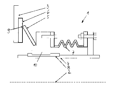
Fig. 1 shows a view of a seal arrangement according to the invention,
Fig. 2 shows a sectional view of a seal arrangement according to the
invention,
Fig. 3 shows a view of a rotating tubular reactor with high-temperature seal
according to the invention, and
Figs. 4 a, b, and c show details of a seal arrangement at the rotating tubular
reactor in Fig. 3.
Figure 1 shows an arrangement of a high-temperature seal 1 according to the
invention between a part 3 rotating round a central axis 2 and which can be a
rotating tubular reactor or a heated drying drum, for example, and a
stationary
part 4, for example a feed connection for a material feed and a connection for
feeding in a heating gas, e.g. flue gas. Here, a sealing ring 5 on the
stationary
part 4 is pressed onto a counter-ring 6 on the rotating part 3. An expansion
joint 7 is used for pre-loading and to compensate for any axial movement and
expansion. Feather keys 8 (for example two or more distributed over the
circumference) prevent the expansion joint 7 from having to absorb the torque
occurring due to the frictional force of the sealing ring 5 acting on the
sliding
surface 9 of the counter-ring 6.
2601
2

CA 02784169 2012-07-31
Figure 2 shows a high-temperature seal 1 according to the invention, where
identical parts have identical reference numerals. The key element of the high-
temperature seal 1 is the sealing ring 5, which is made, for example, from a
high-grade steel. The sealing ring 5 is located on the stationary part 4 and
thus
does not rotate. The expansion joint 7 is preferably designed as a metal
expansion joint and presses the sealing ring 5 onto the counter-ring 6 via a
pressure-loading ring 10. The expansion joint 7 is pre-loaded accordingly for
this purpose. In addition, it compensates for any movement in axial direction
and temperature expansion between the rotating part 3 and the stationary
part 4. The counter-ring 6, for example, is made of a soft Cu-Ni alloy, is
secured to the rotating part 3 and forms the sliding and sealing surface 9
together with the sealing ring 5. As the sliding and sealing surface 9 is at
right
angles to the central axis 2, this sealing surface 9 is able to compensate for
any
radial movement and temperature expansion. Due to the pre-loading force of
the expansion joint 7, the sealing ring 5 changes its incline slightly and the
inner
diameter becomes slightly smaller. If the material of the sealing ring 5 has a
lower temperature expansion coefficient than the material of the pressure-
loading ring 10, the sealing ring 5 is then clamped to the pressure-loading
ring 10. This ensures that the sealing ring 5 slides on the counter-ring 6
instead
of on the pressure-loading ring 10.
Figure 3 now shows a rotating tubular reactor 11 that is heated by means of
flue
gas, where the flue gas is fed into a chamber 12 and heats material inside the
drum 15 via a double shell 13 and heating tubes 14, respectively. The flue gas
here has temperatures of up to 450 C, while the material inside the drum 15 is
heated up to approximately 400 C. In order to guarantee that there are no
leaks, two high-temperature seals 1 each are provided at either end of the
drum
15.
Figure 4 a shows the installation situation at the material discharge area,
where
the sealing ring 5' is pressed against the counter-ring 6' via an expansion
joint 7'
and a pressure-loading ring 10'. The situation at the outer circumference of
the
rotating tubular reactor 11 is shown in Fig. 4 b. Here, the sealing ring 5" is
pressed against the counter-ring 6" via an expansion joint 7" and a pressure-
2601
3

CA 02784169 2012-07-31
loading ring 10". Figure 4 c shows the installation situation at the material
feed,
where two high-temperature seals 1 according to the invention are used here at
the same time. At the outer seal, the sealing ring 5"' is pressed against the
counter-ring 6"' via an expansion joint 7"' and a pressure-loading ring 10"',
while
at the inner seal surrounding the material feed connection, the sealing ring
51v is
pressed against the counter-ring 61v via an expansion joint 7Iv and a pressure-
loading ring 10 'v
In addition to rotating tubular reactors and drum driers, the high-temperature
seal according to the invention can be used in all applications where rotating
parts have to be sealed off against stationary parts at high temperatures
(over
80 to 100 C and up to 1200 C).
2601
4

Representative Drawing
A single figure which represents the drawing illustrating the invention.
Administrative Status

2024-08-01:As part of the Next Generation Patents (NGP) transition, the Canadian Patents Database (CPD) now contains a more detailed Event History, which replicates the Event Log of our new back-office solution.

Please note that "Inactive:" events refers to events no longer in use in our new back-office solution.

For a clearer understanding of the status of the application/patent presented on this page, the site Disclaimer , as well as the definitions for Patent , Event History , Maintenance Fee  and Payment History  should be consulted.

Event History

Description Date
Application Not Reinstated by Deadline 2016-08-01
Time Limit for Reversal Expired 2016-08-01
Deemed Abandoned - Failure to Respond to Maintenance Fee Notice 2015-07-31
Inactive: Cover page published 2013-02-12
Application Published (Open to Public Inspection) 2013-02-05
Inactive: IPC assigned 2013-01-30
Inactive: First IPC assigned 2012-12-20
Inactive: IPC assigned 2012-12-20
Letter Sent 2012-08-13
Inactive: Filing certificate - No RFE (English) 2012-08-13
Application Received - Regular National 2012-08-13
Amendment Received - Voluntary Amendment 2012-07-31

Abandonment History

Abandonment Date Reason Reinstatement Date
2015-07-31

Maintenance Fee

The last payment was received on 2014-06-20

Note : If the full payment has not been received on or before the date indicated, a further fee may be required which may be one of the following

  • the reinstatement fee;
  • the late payment fee; or
  • additional fee to reverse deemed expiry.

Patent fees are adjusted on the 1st of January every year. The amounts above are the current amounts if received by December 31 of the current year.
Please refer to the CIPO Patent Fees web page to see all current fee amounts.

Fee History

Fee Type Anniversary Year Due Date Paid Date
Application fee - standard 2012-07-31
Registration of a document 2012-07-31
MF (application, 2nd anniv.) - standard 02 2014-07-31 2014-06-20
Owners on Record

Note: Records showing the ownership history in alphabetical order.

Current Owners on Record
ANDRITZ AG
Past Owners on Record
GOTTFRIED SCHIFFER
HEINRICH PAULI
WOLFGANG PLIENEGGER
Past Owners that do not appear in the "Owners on Record" listing will appear in other documentation within the application.
Documents

To view selected files, please enter reCAPTCHA code :


To view images, click a link in the Document Description column (Temporarily unavailable). To download the documents, select one or more checkboxes in the first column and then click the "Download Selected in PDF format (Zip Archive)" or the "Download Selected as Single PDF" button.

List of published and non-published patent-specific documents on the CPD .

If you have any difficulty accessing content, you can call the Client Service Centre at 1-866-997-1936 or send them an e-mail at CIPO Client Service Centre.

({010=All Documents, 020=As Filed, 030=As Open to Public Inspection, 040=At Issuance, 050=Examination, 060=Incoming Correspondence, 070=Miscellaneous, 080=Outgoing Correspondence, 090=Payment})


Document
Description 
Date
(yyyy-mm-dd) 
Number of pages   Size of Image (KB) 
Abstract 2012-07-30 1 10
Description 2012-07-30 4 165
Claims 2012-07-30 1 37
Representative drawing 2013-01-08 1 6
Drawings 2012-07-30 4 92
Courtesy - Certificate of registration (related document(s)) 2012-08-12 1 102
Filing Certificate (English) 2012-08-12 1 156
Reminder of maintenance fee due 2014-03-31 1 112
Courtesy - Abandonment Letter (Maintenance Fee) 2015-09-24 1 171
Prosecution correspondence 2012-07-30 10 340