Note: Descriptions are shown in the official language in which they were submitted.
CA 02784607 2014-11-05
WO 2011/072374 PCT/CA2010/001951
TETHERMAST AND FRAG WALL
CROSS REFERENCE TO RELATED APPLICATIONS
This application claims the benefit of priority of U.S. Provisional Patent
Application
No. 61/286,194 filed December 14, 2009.
FIELD OF THE INVENTION
The present invention relates generally to pressure or projectile protection
for a
structure and inhabitants. More particularly, the present invention relates to
methods and
apparatus for restraining and protecting an airbeam structure and human
inhabitants from
pressure waves, flying debris, artillery and mortar fragmentation, and small
arms fire.
BACKGROUND OF THE INVENTION
Air beam structures must be tethered to a support surface or the ground in
order
to fix them in place. Current tether systems and the air beam structures are
vulnerable to
pressure waves, such as hurricane force winds or explosion/blast pressure
waves, as
well as flying debris and small arms fire and other projectiles.
Frag walls protect personnel and equipment from projectiles such as small arms
fire, and flying projectiles.
WO/1990/12160 by Heselden, titled Improvements Relating to Building and
Shoring Blocks, is described in the abstract (with reference numerals removed)
as the
invention provides that wire mesh cage structures are used to provide
structural blocks
usable in building, shoring, walls and the like. The cage is lined with a
geotextile fibrous
material which allows the passage therethrough of water, but not particulate
material such
as cement, sand aggregate which are used as materials for filling the cage.
The invention
discloses novel forms of cage structure and also that the finished blocks can
be coated
with curable synthetic resin to conceal the mesh and provide a decorative
surface finish.
US 5,333,970 (Heselden), US 7,789,592 (Heselden), and US 20100064627
(Heselden) may also form background of the invention.
A commercial product available from HESCO is depicted at:
http://www.hesco.com/prod_con.html
http://www.army-technology.com/contractors/infrastructure/hesco/
- 1 -
RECTIFIED SHEET (RULE 91)
CA 02784607 2012-06-14
WO 2011/072374
PCT/CA2010/001951
The HESCO product relies on wire mesh with fabric to stop fill from pouring
out
between mesh, and provides ballistic resistance with a mass of fill which can
result in an
increased logistic fill cost in resources, time, and money, and cannot be
practically
relocated.
WO/2008/037972 by Milton et al. titled Cellular Confinement Systems, is
described in the abstract (with reference numerals removed) as a cellular
confinement
system for soil, sand or other filler material comprises a number of sub-
assemblies each
made up of a plurality of interconnected open cells of fabric material. The
sub-assemblies
are stackable one on top of the other to provide a structure having at least
one generally
vertical side or end wall. The system further comprises sealing means such as
one or
more skirt portion(s) which are arranged between vertically juxtaposed sub-
assemblies in
use. The skirt portions substantially prevent or minimise the escape of finer
aggregate
material from between the stacked sub-assemblies.
A commercial product DefenCellTM is depicted at:
http://www.defencell.com/
It is desirable to provide a new tether system, and frag wall, which better
secures
and protects air beam structures.
SUMMARY OF THE INVENTION
It is an object of the present invention to obviate or mitigate at least one
disadvantage of previous tether systems and frag walls.
The tethermast and frag wall includes a fabric device having a fill volume
filled
with a fill material on a flexible or compliant mast system. The fill volume
may be a
chambered curtain. The tethermast and frag wall is self supporting, easily
deployed, and
may be used in connection with a structure or may be deployed stand-alone.
In a first aspect, the present invention provides a tether system for an air
beam
structure having flexible tethermast adapted to secure to a support surface,
and a plurality
of tethers extending between the tethermast and the air beam structure.
In a further embodiment, there is provided a frag wall having a hollow
fillable
container having a hinged divider, expandable between a collapsed state and an
expanded state, the frag curtain adapted to receive a frag fill material in
the expanded
state.
In further aspect, the present invention provides a frag curtain having a
support
member extending along a length of the structure, and a flexible curtain
member
suspended from the support member.
- 2 -
RECTIFIED SHEET (RULE 91)
CA 02784607 2012-06-14
WO 2011/072374
PCT/CA2010/001951
In further aspect, the present invention provides a soft coupling for a tether
system
having an inner attachment flap adapted for attachment to an inner side of a
planar
surface, an outer attachment flap adapted for attachment to an outer side of
the planar
suface, the inner attachment flap and the outer attachment flap aligned and
attached
through the planar surface.
In a further aspect, the present invention provides a free-standing frag wall
adapted to be filled with a fill material in order to provide a wall structure
providing ballistic
resistance, the frag wall having a partitioned internal void, and a reinforced
rear panel.
In a further aspect, the present invention provides a self-supporting cellular
frag
wall adapted to be filled with a fill material, the frag wall comprising a
hollow wall section
having a plurality of fill cells formed by partitions extending through the
hollow wall
section, the partitions adapted to support the frag wall prior to filling.
In an embodiment of the invention, the frag wall further includes a reinforced
rear
panel. In an embodiment of the invention, the reinforced rear panel includes
an aramid
material.
In a further aspect, the present invention provides a self-supporting cellular
frag
wall having a plurality of pressure retaining compartments formed by
partitions extending
through the frag wall, the pressure retaining compartments adapted to be
filled with a fill
material, the pressure retaining compartments adapted to at least partially
contain a
pressure wave created in the fill material when the frag wall is struck by a
projectile.
In an embodiment of the invention, the frag wall further includes a reinforced
back
panel.
Other aspects and features of the present invention will become apparent to
those
ordinarily skilled in the art upon review of the following description of
specific
embodiments of the invention in conjunction with the accompanying figures.
BRIEF DESCRIPTION OF THE DRAWINGS
Embodiments of the present invention will now be described, by way of example
only, with reference to the attached Figures, wherein:
...n.J Fig. 1 is an air beam structure including aspects of the present
invention;
Fig. 2 is a tether system of the present invention;
Fig. 3 is a tether system of the present invention;
Fig. 4 is a tether system of the present invention;
Fig. 5 is a tether system of the present invention;
- 3 -
RECTIFIED SHEET (RULE 91)
CA 02784607 2012-06-14
WO 2011/072374
PCT/CA2010/001951
Fig. 6 is a side section view of an air beam structure subject to a blast
pressure
wave (without tethermast and without frag wall);
Fig. 7 is a side section view of an air beam structure subject to a blast
pressure
wave (with tethermast);
Fig. 8 is a side section view of an air beam structure subject to a blast
pressure
wave (with tethermast and with frag wall);
Fig. 9 is a top section view of an air beam structure (at rest);
Fig. 10 is a top section view of an air beam structure subject to a blast
pressure
wave (without tethermast and without frag wall);
Fig. 11 is a top section view of an air beam structure with a tether system of
the
present invention;
Fig. 12 is a perspective section of an air beam member with hug straps;
Fig. 13 is a perspective section of an air beam member with wide hug straps;
Fig. 14 is a perspective section of an air beam structure with air beam sling;
Fig. 15 is a detail of the air beam sling of Fig. 14;
Fig. 16 is a section of a soft coupling of the present invention;
Fig. 17 is further view of the soft coupling of Fig. 16;
Fig. 18 is a top section view of a soft coupling of the present invention;
Fig. 19 is a top section view of a tether system of the present invention
(with soft
coupling, tethermast, and frag wall);
Fig. 20 is a perspective section view of an air beam sling of the present
invention;
Fig. 21 is a top section view of an air beam sling utilizing a single soft
coupling
connection;
Fig. 22 is a top section view of the air beam of Fig. 20 (at rest);
Fig. 23 is a top section view of the air beam of Fig. 20 (in deformation);
Fig. 24 is a perspective view of a soft coupling of the present invention;
Fig. 25 is a detail perspective view of the soft coupling of Fig. 24;
Fig. 26 is a top view of the soft coupling of Fig. 24;
Fig. 27 is a detail view of section B of Fig. 26;
Fig. 28 is a detail view of an alternate design of the soft coupling of Fig.
24 (having
no weld reinforcement #2);
Fig. 29 is a detail view of section B of Fig. 28;
Fig. 30 is a perspective section view of a tether system of the present
invention
with tethermast and frag wall (with external fly shown transparent);
Fig. 31 is a perspective view of a frag wall of the present invention;
- 4 -
RECTIFIED SHEET (RULE 91)
CA 02784607 2012-06-14
WO 2011/072374
PCT/CA2010/001951
Fig. 31A is a side view of a frag wall of the present invention;
Fig. 32 is a perspective view of the frag wall of Fig. 31 (shown in a shipping
or
storage configuration);
Fig. 33 is a detail view of section B of Fig. 31;
Fig. 34 is a side view of a frag wall of the present invention (self-
supporting);
Fig. 35 is a side view of a tether system of the present invention (at rest);
Fig. 36 is a side view of a tether system of the present invention (in
deformation);
Fig. 37 is Sketch of a curtainwall segment showing two partitioning options.
The
walls are packed concertina-style for storage and shipping and filled on-site
with local
geological materials;
Fig. 38 is a one embodiment of a method for packing and deployment of multiple
linked curtainwall segments requiring minimal mechanized support;
Fig. 39 is a top view depiction of a projectile penetrating a (prior art) wall
of
granular material without internal partitioning;
Fig. 40 is a top view depiction of a projectile impact upon a partitioned
curtainwall
with reinforced fabric back-panel;
Fig. 41 is an isometric view of a frag wall support of the present invention;
Fig. 42 is an end view of the frag wall of Fig. 41;
Fig. 43 is an isometric view of an embodiment of a frag wall of the present
invention;
Fig. 44 is a side view of the frag wall of Fig. 43;
Fig. 45 is a front isometric view of an embodiment of a frag wall of the
present
invention; and
Fig. 46 is a rear isometric view of the frag wall of Fig. 45.
DETAILED DESCRIPTION
Generally, the present invention provides a method and system for tethering a
structure, such as an air beam structure and for providing a physical
protective barrier to
protect the structure from pressure waves or projectiles or both.
Referring to Fig. 1 a structure (10) includes a frag curtain or frag wall (20)
surrounding at least a portion or portions of the structure to protect the
structure from
projectiles or pressure waves or both. The frag curtain or frag wall may also
serve as a
thermal barrier to shield the structure from the heat or fireball from a blast
or other
explosion or fire.
- 5 -
RECTIFIED SHEET (RULE 91)
CA 02784607 2012-06-14
WO 2011/072374
PCT/CA2010/001951
Referring to Fig. 2, an air beam (30) may be attached to the support surface
(40)
(ground, floor, slab, footing or other support surface) by a plurality of
tethers (50)
extending between an anchor (60) and the air beam (30). As there may be gaps
between
adjacent air beam arches, an external fly (70) may extend across the surface
formed
across the air beam arches to provide external closure. Similarly, an internal
liner (80)
may extend across the surface formed across the air beam arches to provide
internal
closure. Pressure/blast direction (100).
Referring to Fig. 3, the air beam arch may be attached to the support surface
by a
plurality of tethers (50) extending between the air beam and a tethermast
(110) , the
tethermast anchored to the ground or weighted. The tethermast is preferably
relatively
flexible or compliant in order to absorb or dissipate lateral loads exerted on
the tethermast
(110). Note that the tethermast is depicted aligned with the air beam, but
that is but one
embodiment. In another embodiment the tethermast(s) may be placed in the gap
between
adjacent air beams. The tethermast may be flexible in one plane, for example
parallel to
the expected direction of the blast or pressure wave, or may be flexible in a
plurality of
planes. The tethermast (110) may be flexible in terms of a compliant member or
may
include a leaf spring or other spring system or energy dissipating system and
may
optionally be damped.
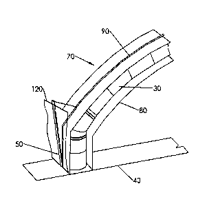
Referring to Fig. 4, a protective frag curtain or frag wall may be installed
external
to structure to provide protection from projectiles or pressure waves or both.
The frag
curtain or frag wall may be supported by a support member (120), extending
between two
or more tethermasts, such as a rope, cable, or webbing or the frag curtain or
frag wall
may be self supporting on the support surface (40) or both. The frag curtain
or frag wall
may be secured to the support surface (40) or may be weighted to be supported
in
tension by gravity.
Referring to Fig. 5, a reinforcing member (130), such as webbing may extend
across the external fly for attaching additional tethers (50). As shown in
this Fig. 5, a
centre tether may connect with the air beam (30) (for example the backbone
cable (90) or
other device for transferring loads) and additional, side or transverse
tethers (50) may
connect with the reinforcing member or external fly or both (in a V-shape).
Referring to Fig. 6, an air beam structure may have a primary habitable space
(150), defined as a portion of the structure, between the support surface (40)
and a
selected height, such as 5' or 10' or more depending on the usage of the
primary
habitable space (150). In the event of a pressure wave or pressure spike, for
example a
blast wave from an explosion, a portion of the air beam structure may be
forced into the
- 6 -
RECTIFIED SHEET (RULE 91)
CA 02784607 2012-06-14
WO 2011/072374
PCT/CA2010/001951
primary habitable space risking injury to live occupants or damage to property
or both.
Area Intrusion: 6.1%. In addition, the deflection of the air beam (30) allows
a portion of
the pressure wave to be transmitted from the exterior of the structure to the
interior of the
structure, again with the risk of injury to live occupants or damage to
property or both.
Referring to Fig. 7, the tethermast (110) of the present invention reduces the
intrusion of the deformed structure into the habitable space (150) and reduces
the
transmission of the blast wave into the interior of the structure. Area
Intrusion: 2.2%.
Referring to Fig. 8, the frag wall or frag curtain (20) of the present
invention
reduces the intrusion of the deformed structure into the habitable space and
reduces the
conveyance of the blast wave into the interior of the structure. Area
Intrusion: 0.8%.
Referring to Figs. 9 and 10, an unsupported external fly (70) is typically
used to
cover the spaces between adjacent air beam members (see also Fig. 2). In the
event of a
pressure or blast wave, the ground tethers hold the air beam members in place,
but due
to deflection the external fly may move from an at rest state (Fig. 9) to a
deflected state
(Fig. 10) resulting in the transmission of a portion of the blast wave to the
interior (170) of
the structure. Transmitted Blast (180).
Referring to Fig. 11, the air beam member and the external fly may be tethered
(50) to the tethermast (110). An air beam connection member, such as a rope or
cable or
webbing etc., may extend around the air beam member, providing a connection or
connections, soft coupling (200) through or across the external fly (70) to
one or more
tethermast (110). An air beam sling (190) may extend around the air beam
member (30),
providing a soft-connection or soft-connections through or across the external
fly (70) to
one or more tethermast (110).
Referring to Fig. 12, the air beam connection member may include a hugstrap of
the type disclosed in US patent publication number US20100139175. Mid Hug
Strap
(210). Bottom Hug Strap (210).
Referring to Fig. 13, the air beam connection member may include a wide
hugstrap which extends around the air beam and which may be free to move
relative to
the air beam or may be attached to the air beam by stitching, welding,
adhesive,
VelcroTM, or other attachment means to provide a distributed load pickup. In
Fig. 3, the
wide hugstrap and the air beam are attached at three locations, 90 degrees,
180 degrees,
and 270 degrees (relative to the distributed load pickup (220)). This
attachment, attach
(215), is for holding the wide hugstrap in a selected position only and is not
a structural
connection.
- 7 -
RECTIFIED SHEET (RULE 91)
CA 02784607 2012-06-14
WO 2011/072374
PCT/CA2010/001951
Referring to Fig. 14, the air beam connection member may include an air beam
sling (190)(see also above Fig. 11). In this figure, the external fly is shown
transparent
and in the view shown, we are looking "through" the external fly. The air beam
sling (190)
may include reinforcing (230) members, such as webbing or other reinforcing
means.
Tethers (50) extend between the air beam sling and tethermasts.
Referring to Figs.15-18, the loads are transmitted through or across the
external
fly through the use of a soft coupling. A number of attachment flaps
(240)(four shown) are
positioned in a "+" configuration, and sewn as shown through the fly. A number
of
grommets or other fastening means are provided to attach tethers on the
inside, interior
(170), extending to the air beam(s) and attach tethers (50) on the outside,
exterior (160),
extending to the tethermast(s).
Referring to Fig. 16, nylon webbing (250); several options for attachments to
tethers e.g. grommets. These flanges (260) sewn-through to matching flap on
the other
side; this transfers load independently of strength of fly. If treated with
weather seal some
holes should not have major seapage problem more than via through holes
initially
proposed; the internal space behind this tab is inaccessible.
Referring to Fig. 17, soft couplers (200) can be made from single folded
webbing
strip saw-through or rivets.
Referring to Fig. 18, grommets (270) holes or other options. Nylon webbing
(250)
reinforcement. Heavily sewn through (280).
Referring to Fig. 19, a tether system is shown including a number of different
tie
downs, including tethermasts (110), frag curtain or frag wall (20), cross-
ties, soft couplers,
hugstraps, and air beam slings (190). Secure to top-cable (120) of tethermast
curtain.
Tether mast upper beam cross section (290).
Referring to Fig. 20, the air beam sling (190) may extend along a significant
length
of the air beam member (30).
Referring to Figs. 21-23, the design may include a single soft coupling (200)
(Fig.
21) or a plurality of soft couplings (200) (Fig. 22-23). The soft coupling
(200) may be
aligned with the air beam or may be offset. In a blast / pressure wave, the
soft coupling
connection will encounter shear stress/strain (310) rather than peel. Air beam
sling (190)
lace down (300) via grommet (270).
Referring to Figs. 24-30, the soft coupler, soft coupling (200), may extend
along a
significant length to correspond to a significant length of the air beam. A
plurality of
attachment flaps (240) may be arranged to provide reinforcing to the weld. An
edge
reinforcing member (320) may be attached to the attachment flaps (240).
Referring to
- 8 -
RECTIFIED SHEET (RULE 91)
CA 02784607 2012-06-14
WO 2011/072374
PCT/CA2010/001951
Figs. 24-27, a weld reinforcement member, weld reinforcement (330), may be
used
between the edge reinforcing member (320) and the attachment flaps (240). Weld
reinforcement-2 (335). Referring to Figs. 28-29, the edge reinforcing member
(320) and
the attachment flaps (240) may be connected directly. Keder (340) RF welded
(350) to
Weld re-inforcement-1 (337).
Referring to Fig. 30, the tethermast (110) may be protected by a frag wall of
a
selected height, Frag Wall or Frag Curtain (20). As shown, the frag wall may
extend up a
portion of the tethermast, but in an alternate embodiment, the frag wall may
extend up a
substantial height, even to the point of exceeding the height of the
tethermast. In this
figure, the external fly is shown transparent.
Referring to Figs. 31-35, the frag wall (370) may include a hollow fillable
structure
which may be transported in a collapsed state (Fig. 32) and may be expanded to
an
expanded state (Fig. 31) to provide a frag wall volume fillable with a frag
wall fill. A divider
(380), 4mm DASL board Dividers (12 required), breaks the frag wall volume into
smaller
compartments. The divider (380) may be hinged to allow movement between the
collapsed state and the expanded state (Fig. 33). A fabric hinge, welded/glued
fabric
hinge (460), may be constructed of a flexible material welded or glued to the
divider,
40mnn (465), 50mm (467). Tie Straps (400) to Tether Mast (110).
The internal partitioning and tough back-panel allows great height/width with
stability and ballistic resistance.
The internal partitioning improves the ballistic resistance performance by
impeding
the 'rate of cavity growth' imparted by the projectile. Embodiments of the
invention have
shown proven stability of 8 foot wall and the proof of resistance to ballistic
penetration. In
one embodiment the aspect-ratio of the wall is about 4:1 which is at a higher
range of
suitable aspect-ratio. This relatively higher aspect-ratio provides for more
efficient use of
fill. The walls may be tapered or the taper may be increased as required, for
example an
increase to 1000mm from 600mm at base if greater stability is required, Bell
bottom Style
(430) for Stability. A double-wall, of 4:1 aspect ratio, may be used for
greater stopping
power, for example to stop a rocket propelled grenade (RPG).
The internal partitioning or bracing acting under tension to maintain
hydrostatic
pressure of fill. The internal partitioning must be semi-rigid (vs fabric) to
allow the empty
curtainwall to be self-supporting and keep shape during fill. The semi-rigid
partitioning is
key to ballistic performance since the partitions restrict cavity growth. The
heavier DASL
fabric skin is also key to maintaining hydrostatic forces of fill. An aramid
back panel, Back
- 9 -
RECTIFIED SHEET (RULE 91)
CA 02784607 2012-06-14
WO 2011/072374
PCT/CA2010/001951
Panel (410) to be 31oz KevlarTM material, of the frag wall (370) improves
ballistic
resistance.
The internal partitions may be set parallel to the expected direction of
projectile
(i.e. orthogonal to front surface or front panel of the frag wall), Blast Wave
(450), or
angled to meet particular specifications. Angled partitions help provide an
inherently
stronger self-supporting member. However, the end-frames for each wall segment
may
be used to augment stability, keep the shape (especially on deployment for the
90 degree
partitions). Ninety (90) degree angled partitions are desirable for improved
folding, ease
of fabrication and uniformity of ballistic resistance. The metal end-frames
are more
important to 90 degree partitioning. The metal end-frames are key to support
hopper fill
process. Outriggers of base of metal end-frames can be extended as required
for
additional stability for uneven terrain. Cable or cables running through
sleeve at or near
top of the wall may be used to ensure entire wall tied together to provide
further
resistance to overturning.
We refer to it as a "curtain wall" when it is empty, capable of defending
against
industrial debris in an explosion. We refer to it as a frag wall when it is in
geotextile form
or with fill and defending against armed fire, ballistics, mortar and
artillery fragments.
The frag wall may be stand-alone. As shown, the cross-section shape being
broader at the base than the top provides improved stability. A series of frag
walls could
be assembled to form a bastion.
The frag wall includes a series of cells, created by fusing PVC coated
materials
into a corrugated form or geotextile wall section. The wall sections require
ancillary
support such as from our tether mast or the support of other building walls or
support
member. There are no wires or hard framed elements to our system.
The frag wall may be conveniently emptied for redeployment or reuse, for
example by toppling it over and then lifting a portion of the wall to allow
the fill to pour out
of the bottom, Double flap (420) at bottom to empty, or the top, fill flap
(390), or both.
Referring to Fig. 31A, the flexible tethermast may be connected to or integral
with
a base to support the frag curtain (see also the tethermast/base configuration
of Fig. 30,
but the 'L-shaped' base/tethermast is in the reverse orientation with the base
extending
away from the blast direction). In Fig. 30 the frag wall sits proximate the
base/tethermast
(110), and in Fig. 31A the frag curtain or frag wall sits on the base (440).
The weight of
the filled frag wall (370) or frag curtain provides stability to the base
(440) and tethermast
(110) so the system is free-standing or self-supporting.
- 10 -
RECTIFIED SHEET (RULE 91)
CA 02784607 2012-06-14
WO 2011/072374
PCT/CA2010/001951
The frag wall fill may be a wide variety of materials including sand, cement,
water,
soil, clay, and other fills known to one skilled in the art or mixtures or
combinations
thereof. The frag wall includes an upper fill flap to allow closure of the
frag wall after the
frag wall fill is added. The frag wall includes a lower flap (420) to allow
the drainage or
removal of the frag wall fill for demolition of the frag wall for transport to
another location.
The back side (being the side opposite the side expected to experience the
blast or
pressure wave (450)) may utilize fiber reinforced materials, such as aramid
fibers or para-
aramid fibers, such as KevlarTM.
Referring to Fig. 34 (and Fig. 30), the frag wall (370) may rest upon the
support
surface (40) and be connected to the tethermast (110)(or tethernnasts).
External Face
(470).
Referring to Figs. 35-36, an extension flap (480) may be attached to the
external
fly and extend over the frag wall (or frag curtain). Extension flap (480)
welded on fly
passes over curtain system as rain/snow/leaf shed; plastic tube sheath over
curtain cable;
many options for lay-up of multiple curtain layers to be optimized by
modelling or testing.
Referring to Fig. 36, a pressure wave, pressure (490), such as a blast wave,
sets the
tethermast into pre-tension providing increased stiffness to the main load on
the structure.
Initial blast load to external curtain sets tethermast into pre-tension
reinforcing stiffness to
main load on shelter.
Referring to Fig. 37, the high yet stabile aspect-ratio of the curtainwall
improves its
efficiency in providing maximum ballistic protection without excessive fill of
current block
bastion-type walls. The stability and ballistic performance of the curtainwall
relates to its
unique design involving use of semi-rigid internal partitioning as shown in
Fig. 37. As
used herein, 'semi-rigid' refers to a lightweight yet flexible board-type
material. 2mm
fiberglass sheet might be considered for illustration purposes, although many
options may
suffice including composite vinyl boards (DASLboard). Optional cavity fills
(510).
Each partition should be capable of supporting a distributed vertical load
along
each vertical edge of about 2-3kgs, being the approximate deadweight of the
fabric
material of the front and back of the local curtainwall segment to which it is
attached. The
thickness, height, and vertical taper profile of the wall are adjustable
dependent on the
threat to be countered. The partitions may be diagonal or 'straight-across'
with respect to
the line of the wall. Simple metal or composite end-frames (500) for each
segment as
shown in Fig. 37 provide transverse shear and 'toppling' resistance during
deployment
prior to filling. Single or double-tapered walls as required.
- 11 -
RECTIFIED SHEET (RULE 91)
CA 02784607 2012-06-14
WO 2011/072374
PCT/CA2010/001951
Referring to Fig. 38, akin to corrugated cardboard, one role of the
partitioning is to
act as internal bracing to provide both vertical and transverse stiffness to
the fabric
curtainwall. Diagonal partitioning allows the wall to be fully self-supporting
prior to fill and
to maintain a 'tight' shape without slumping during and after filling with
geologic materials
including soils, sand, or crushed rock. Another option exists to allow
insertion of a
bladder within each partitions for water fill of the 'cells' or cavities
defined by the
partitioning. When a line of curtainwall segments is deployed they may be tied
together by
means of the intermediary frame segments as well as a longitudinal cable along
the top
edge of the wall. By this means the entire wall will resist any overturning
action imparted
to any individual segment, for example by impact of a projectile upon the
individual
segment. Shipping/Deployment Crate (530)(-6 wall segments) 8.5' h x 4.5' w x
10' I.
Space (540) available for tethermast components. Concertina sections (550) pre-
linked at
factory. Box skid or skis (560). Initial stabilizing stays (520). Ground pegs
(580) stake wall
position while deploying. Shipping crate dragged by bobcat.
Referring to Figs. 39 and 40, the second important role of the internal
partitioning
concerns the frag wall resistance to ballistic penetration.
Fig. 39 provides a depiction of a wall of granular fill without internal
partitioning
and without a reinforced back panel. Ballistic penetration of a fluid or
granular substance
(that is, having low bulk shear resistance or strength) such as geological
material relates
directly to the 'rate of cavity growth' caused by the passage of the
projectile. Generally,
the kinetic energy imparted by the impact of the projectile causes the grains
(or fluid for
fluid-filled cavities) to be flung outwards in a manner to cause a void around
the projectile.
The ease by which this cavity is formed and expanded relates directly to the
depth of
penetration. Expanding temporary cavity (700). Compacted and accelerated zone
(710).
Compression front (720). Compacted and expanding material (730). Weak backing
allows
material and projectile to 'blow out' backside (740). Cavity collapse (750).
Fig. 40 provides a depiction of a wall of the present invention, having
internal
partitions and a reinforced back panel. The front or 'threat side' fabric
panel of the
curtainwall requires only sufficient strength to contain the hydrostatic
pressure of the fill
and stresses from rough filling; this panel is expected to be locally
penetrated by high
energy projectiles such as bullets or bomb fragments. However, the membrane
action of
the remaining fabric of the front panel and especially the internal
partitioning of the
curtainwall greatly impedes the subsequent rate of internal cavity growth. The
fill material
accelerated by the projectile compression wave is restrained by the bending
and
membrane resistance of the partition material. Membrane partition (800). High
strength
- 12 -
RECTIFIED SHEET (RULE 91)
CA 02784607 2012-06-14
WO 2011/072374
PCT/CA2010/001951
membrane bracing (810). Expanding temporary cavity (820). Membrane action
retards/distorts cavity growth, increases compaction (830). Compression zone
(840). High
compaction zone (850). Distributed compression taken by strong-back membrane
(860).
Cavity collapse (870). Residual compaction (880).
The back panel of the curtainwall is specially reinforced such as with aramid
fiber
while retaining flexibility to act primarily in membrane action. Kevlar0 or
fiberglass are
also suitable for fabrication or reinforcement of the back panel. The
compressed and
accelerated material ahead of the projectile is retained by the tough back
membrane. The
action of the back membrane greatly reduces the cavity growth and eliminates
the back
'blow out' of the fill material. Therefore, the compression imparted in the
material by the
projectile is ultimately used to retard its penetration. The flexing membrane
action
combined with toughness of the back panel is required for this performance.
In the event the back panel were to fail, the ultimate failure would be
rupture from
over-pressurization from the distributed load of the fill material rather than
localized
shear-type puncture by the projectile itself.
Referring to Figs. 41 and 42, a frag wall support (600) includes a stabilizing
member and a support frame. Slot (590).
Referring to Figs. 43 and 44, a frag wall support (600) may include a base
(440)
upon which the frag wall (370) sits, a flexible member extending upward from
the base,
the frag wall supported or restrained at least partially by a connection
between the frag
wall and an upper portion of the flexible member. The flexible member may be,
for
example, a tethermast (110) of the present invention.
Referring to Figs. 45 and 46, a section of a frag wall is shown. The
partitions or
end panels or both may be constructed of or reinforced with, for example,
corrugated
plastic, such as Core PlastTM. A webbing pad (630) may be formed into portions
of the
front panel or rear panel or both to receive a webbing material. The webbing
(640) may
be used to connect the section of frag wall to a support.
In the preceding description, for purposes of explanation, numerous details
are set
forth in order to provide a thorough understanding of the embodiments of the
invention.
However, it will be apparent to one skilled in the art that these specific
details are not
required in order to practice the invention.
The above-described embodiments of the invention are intended to be examples
only. Alterations, modifications and variations can be effected to the
particular
embodiments by those of skill in the art without departing from the scope of
the invention,
which is defined solely by the claims appended hereto.
- 13 -
RECTIFIED SHEET (RULE 91)