Note: Descriptions are shown in the official language in which they were submitted.
CA 02785413 2012-08-10
= PL6499CA_Final ver.
- 1
TITLE OF THE INVENTION
X-RAY DIFFRACTION INSTRUMENT
BACKGROUND OF THE INVENTION
1. Field of the Invention
The present invention relates to X-ray diffraction
instruments, and particularly to X-ray diffraction
instruments for detecting X-ray diffraction patterns two-
dimensionally and estimating residual stresses of
measurement objects.
2. Description of Related Art
X-ray diffraction instruments are used as a non-
destructive inspection tool for measuring various material
properties (such as crystallographic structure, composition
and residual stress) . Goniometers, zero-dimensional
scintillation counters (SC), one-dimensional position
sensitive detectors (PSD), etc. are commonly and widely
used to obtain X-ray diffraction data (such as intensity
and angle of diffraction) . However, these instruments offer
only zero-/one-dimensional diffraction data by a single
measurement. Thus, a complicated actuator and a long total
measurement time are needed to obtain sufficient
diffraction data required for a thoroughly satisfactory
material analysis.
CA 02785413 2012-08-10
PL6499CA_Final ver.
2 -
To overcome this disadvantage, X-ray diffraction
instruments including a two-dimensional X-ray detector
which provide a larger amount of diffraction information in
a shorter period of measurement time are used. Examples of
two-dimensional X-ray detectors include two-dimensional
position sensitive proportional counters (PSPC) and imaging
plates (IP). Imaging plates are a type of ionizing
radiation image detector in which a photostimulable
phosphor such as BaFX:Eu2+ (X = Br, I) is applied on a
support plate made of a plastic or the like.
JP-A 2000-146871 discloses a micro X-ray diffraction
instrument and a method of measurement, in which a micro
area of a specimen is irradiated with an X-ray beam and the
X-ray beams diffracted by the specimen are detected by a
two-dimensional X-ray detector. The two-dimensional X-ray
detector used in this micro X-ray diffraction instrument is
a cylinder made of a photostimulable phosphor, and is
placed in such a manner as to surround the specimen. The
specimen is tilted (e.g., by 45 ) so that both the X-ray
beams diffracted in directions tangential to the specimen
surface and the X-ray beams diffracted in directions normal
to the specimen surface can be detected by the
photostimulable phosphor X-ray detector. By using the JP-A
2000-146871 X-ray diffraction instrument, sufficient X-ray
diffraction data can be captured by the photostimulable
CA 02785413 2012-08-10
PL6499CA_Final ver.
3 -
phosphor detector by rotating the specimen around only one
axis (normal to the specimen surface), which is
advantageous over most conventional X-ray diffraction
instruments requiring rotations about two axes. Thus, this
X-ray diffraction instrument has the advantage of simple
structure, high diffraction intensity and short total
measurement time.
JP-A 2005-351780 discloses an X-ray diffraction
instrument including a two-dimensional X-ray detector that
provides transmission diffraction measurement. This X-ray
diffraction instrument includes: a specimen table for
horizontally holding a specimen; an X-ray emitter for
irradiating the specimen with an X-ray beam; an arm for
actuating the X-ray emitter in such a way that the incident
angle of the emitted X-ray beam relative to the specimen is
set at a desired angle from 0 to 90 ; and a partially-open
cylinder made of a storage (photostimulable) phosphor that
surrounds the specimen table for detecting the X-ray beams
diffracted by the specimen. The phosphor cylinder is placed
in such a manner that its axis is perpendicular to the
emitted X-ray beam. The phosphor detector portion of the
cylinder barrel extends circumferentially from 180 to 360
as measured from the horizontal (parallel to the table
surface) on the side of the X-ray emitter, and more
preferably from 100 to 360 , and the other portion of the
CA 02785413 2012-08-10
PL6499CA_Final ver.
4 -
cylinder barrel is open. The JP-A 2005-351780 X-ray
diffraction instrument provides transmission diffraction
measurement as well as reflection diffraction measurement.
JP-A Hei 6(1994)-317484 discloses an X-ray exposure
system for micro-area stress measurement including (from
upstream to downstream along the X-ray path): a slit and
first (upstream) screen; a sample stage mounted on a
rotatable goniometer; an imaging plate on a support that is
mounted on an arm rotatable about the emitted X-ray axis;
and a second (downstream) screen just in front of the
imaging plate. The emitted X-ray beam passes through the
slit and first screen and is incident on a micro-area (e.g.,
100 m to 1 mm square) of a sample, and several discrete X-
ray diffraction arcs (each being a part of a Debye ring)
obtained by changing the X-ray angle incident on the sample
several times are exposed on the same single stationary
imaging plate. According to this JP-A Hei 6(1994)-317484,
several discrete X-ray arcs can be detected by a single
measurement with a high angular accuracy, thus enabling
micro-area stress measurement of polycrystalline materials
in a short period of time.
JP-A 2005-241308 discloses an X-ray diffraction system
in which a measurement object (a railway rail) is
irradiated with X-ray and an image of the X-ray diffraction
ring from the measurement object is captured. This X-ray
CA 02785413 2012-08-10
PL6499CA_Final ver.
-
system includes: an X-ray emitter for emitting the X-ray
and an X-ray detector for storing the energy of the X-ray
diffraction ring and producing the image of the diffraction
ring. The X-ray emitter and the X-ray detector are mounted
5 on a holder in such a manner the X-ray incident angle
relative to the measurement object is fixed at a single
angle. According to this JP-A 2005-241308, the X-ray
diffraction system can perform X-ray diffraction
measurement simply and conveniently. Also, the system is
easy to use, cheap to manufacture and portable. In addition,
the physical condition (such as residual stress) of a
measurement object (a railway rail) can be evaluated by
comparing the diffraction rings of the measurement object
and of a standard specimen (an iron standard powder).
However, the X-ray diffraction instruments of JP-A
2000-146871 and JP-A 2005-351780 require an actuator for
adjusting the position and/or orientation of the specimen
and/or the X-ray emitter, and thus have disadvantages of
complicated structure and large size. In addition, the two-
dimensional X-ray detectors used in the above disclosures
are cylindrical in form, and surround a specimen for
detecting the X-ray beams diffracted by the specimen.
Therefore, there is some limitation on the size and shape
of specimens measurable by these X-ray diffraction
instruments. In general, specimens measurable by
CA 02785413 2012-08-10
PL6499CA_Final ver.
6 -
conventional X-ray diffraction instruments are limited to
relatively small objects (such as laboratory samples).
Also, the X-ray exposure system for micro-area stress
measurement of JP-A Hei 6(1994)-317484 requires a
goniometer for rotating a sample stage on which a specimen
is mounted, and thus has a disadvantage of complicated
structure and some limitation on the size and shape of
specimens to be measured. Furthermore, JP-A Hei 6(1994)-
317484 describes that, in order to measure the micro-area
stress of the measurement specimen, a standard powder is
placed on the specimen and that the X-ray is irradiated to
both the specimen and the standard powder at the same time.
However, JP-A Hei 6(1994)-317484 is silent to a fixing
method of the standard powder to the specimen.
Recently, there has been an increasing demand for on-
site non-destructive inspection of the conditions (such as
material abnormality and deterioration) of structural
components of large apparatuses used in various plants. As
described in JP-A 2000-146871, JP-A 2005-351780 and JP-A
Hei 6(1994)-317484, most conventional X-ray diffraction
instruments are large in size, and there is some limitation
on the size and shape of specimens. Thus, conventional X-
ray instruments are very difficult to use as a tool for
inspecting structural components of large apparatuses both
non-destructively and on-site.
CA 02785413 2012-08-10
PL6499CA_Final ver.
7 -
The X-ray diffraction system of JP-A 2005-241308 has
advantages in that the X-ray emitter can stably impinge X-
ray on a large measurement object at a predetermined fixed
incident angle, and any actuator for rotating the
measurement object is not required. However, JP-A 2005-
241308 does not describe any method for setting the
standard specimen required for the residual stress
measurement. This is probably because the JP-A 2005-241308
technology is practically limited to the top surface of a
railway rail. Also, this disclosure does not describe any
measure to prevent leakage of X-ray emitted from the X-ray
emitter or scattered by the measurement object.
When X-ray diffraction measurement of large apparatuses
in plants or other systems is performed on-site, the
measurement surfaces (the surfaces to be measured) may
often be vertical or face downward. In such cases, it is
difficult to stably attach a standard powder on a
measurement surface, thus making accurate measurement and
estimation difficult. Also, contamination by foreign
materials is unacceptable in some plants. In such
environments, attaching a standard powder on a measurement
surface without scattering the powder is a particularly
important requirement. In addition, it is desirable for
operator safety to prevent X-ray leakage.
CA 02785413 2012-08-10
PL6499CA Final ver.
- 8 -
SUMMARY OF THE INVENTION
In order to address the above problems and requirements,
it is an objective of the present invention to provide an
X-ray diffraction instrument without any actuator for
adjusting the position and/or orientation of a measurement
object, in which: there is no particular limitation on the
size and shape of the measurement object; a standard powder
can be stably attached on the surface of the measurement
object; and X-ray leakage is prevented.
According to an aspect of the present invention, there
is provided an X-ray diffraction instrument including:
a two-dimensional plate-like X-ray detector;
an X-ray emitter integrated with the X-ray detector so
as to penetrate the plate of the X-ray detector;
a cylinder-like shield to define an orientation of the
X-ray emitter and to prevent X-ray leakage, the X-ray
detector being attached to one open end of the cylinder-
like shield; and
a standard powder attachment device to attach a
standard powder for X-ray diffraction measurement to a
surface of an object to be measured. The X-ray diffraction
instrument can perform an X-ray diffraction measurement to
an object larger than the X-ray detector thereof.
In the above aspect of the present invention, the
following modifications and changes can be made.
CA 02785413 2012-08-10
PL6499CA_Final ver.
9 -
i) The standard powder attachment device is an injector
to inject a dispersion of the standard powder in a
dispersion medium; and the injector is integrated with the
X-ray detector so as to penetrate the X-ray detector.
ii) The standard powder attachment device is a polymer
sheet having the standard powder dispersed therein; and the
polymer sheet covers the other open end of the cylinder-
like shield facing a surface of the object to be measured.
The polymer sheet is attached to the object surface by
pushing the polymer sheet against the object surface to be
measured.
iii) A thickness of the polymer sheet is from 0.1 to
0.5 mm.
iv) The cylinder-like shield is detachable and easily
exchangeable for another cylinder-like shield.
v) The X-ray emitter includes a sighting device.
vi) The X-ray detector is an imaging plate including a
photostimulable phosphor layer.
vii) The cylinder-like shield blocks visible light.
viii) The imaging plate is housed in a cartridge that
transmits X-ray but blocks visible light.
ix) The imaging plate is detachable and easily
exchangeable for another imaging plate.
x) The X-ray detector is a position-sensitive
proportional counter.
CA 02785413 2012-08-10
PL6499CA_Final ver.
- 10 -
[Advantages of the Invention]
According to the present invention, it is possible to
provide an X-ray diffraction instrument without any
actuator for adjusting the position and/or orientation of a
measurement object, in which there is no particular
limitation on the size and shape of the measurement object
and a standard powder can be stably attached on a surface
of the measurement object. The invented X-ray diffraction
instrument is small in size, and can perform accurate X-ray
diffraction measurement of stationary immovable objects
(e.g., on-site inspection of structural components of large
apparatuses) without limitation on an orientation of the
measurement surface. In addition, X-ray leakage is
prevented for operator safety.
BRIEF DESCRIPTION OF THE DRAWINGS
FIG. 1 is a schematic illustration showing a
perspective view of an embodiment of an X-ray diffraction
instrument according to the present invention.
FIG. 2 is a schematic illustration showing a
perspective view of an example of an injector used in the
invented X-ray diffraction instrument.
FIG. 3 is a schematic illustration showing perspective
views of cylinder-like shields having different tilt angles
Ps.
CA 02785413 2012-08-10
PL6499CA_Final ver.
- 11 -
FIG. 4 is a schematic illustration showing perspective
views of another embodiment of an X-ray diffraction
instrument according to the present invention.
FIG. 5 is a schematic illustration showing a
perspective view of an imaging plate as an example of a
two-dimensional X-ray detector used in the invented X-ray
diffraction instrument.
FIG. 6 is a schematic illustration showing a
perspective view of still another embodiment of an X-ray
diffraction instrument according to the present invention.
FIG. 7 is a schematic illustration showing a
perspective view of a preferred example of the X-ray
diffraction instrument according to the present invention.
FIG. 8A is a schematic illustration showing a side view
of the X-ray diffraction measurement of a measurement
object by means of the X-ray diffraction instrument of the
present invention.
FIG. 8B is a schematic illustration showing a side view
of the X-ray diffraction measurement of a standard powder
provided at the measurement point by means of the X-ray
diffraction instrument of the present invention.
FIG. 9 shows an example of a visualization of the X-ray
diffraction rings from a measurement point and a standard
powder.
FIG. 10 is a schematic illustration showing an X-ray
CA 02785413 2012-08-10
= PL6499CA_Final ver.
12 -
diffraction ring for explaining parameters required for the
cosa. method calculation.
DETAILED DESCRIPTION OF THE PREFERRED EMBODIMENTS
Preferred embodiments of the present invention will be
described below with reference to the accompanying drawings.
In the drawings, like parts are designated by like
reference numerals without repeating the description
thereof. The invention is not limited to the specific
embodiments described below, but various combinations and
modifications are possible without departing from the
spirit and scope of the invention.
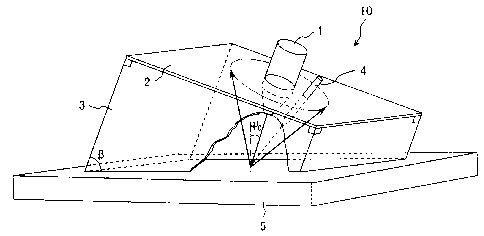
Figure 1 is a schematic illustration showing a
perspective view of an embodiment of an X-ray diffraction
instrument according to the present invention. As
illustrated, an X-ray diffraction instrument 10 of the
present invention includes: a two-dimensional plate-like X-
ray detector 2; an X-ray emitter 1 integrated with the X-
ray detector 2 so as to penetrate the plate of the X-ray
detector 2; and a cylinder-like shield 3 to define an
orientation of the X-ray emitter 1 and to prevent X-ray
leakage. The X-ray detector 2 is attached to one open end
of the cylinder-like shield 3 in such a manner that the
perimeter of the open end of the cylinder-like shield 3
abuts the perimeter of the detector 2. As illustrated in
CA 02785413 2012-08-10
= PL6499CA_Final ver.
13 -
FIG. 1, the X-ray diffraction instrument 10 can perform an
X-ray diffraction measurement to a measurement object 5
whose size is larger than the X-ray detector 2. The X-ray
diffraction instrument 10 further includes, as a standard
powder attachment device to attach a standard powder for X-
ray diffraction measurement to a surface of the measurement
object 5, an injector 4 to inject a dispersion of the
standard powder in a dispersion medium.
An X-ray beam emitted from the X-ray emitter 1 (e.g.,
X-ray tube) is incident on and diffracted by the
measurement object 5, and then the diffracted X-ray beams
are incident on and detected by the X-ray detector 2 where
the diffraction pattern of the measurement object 5 is
recorded. Herein, the X-ray beams (the emitted X-ray beam
and the diffracted X-ray beams) are surrounded and blocked
by the cylinder-like shield 3. Thus, the above diffraction
measurement can be carried out safely without any X-ray
leakage. Preferably, the X-ray emitter 1 is equipped with
an unshown sighting device (such as a laser pointer) for
visibly showing a point on the measurement object 5 to be
irradiated with the emitted X-ray beam. By using this
sighting device, the X-ray diffraction instrument 10 can be
easily positioned in such a manner that the X-ray emitter 1
emits an X-ray beam onto an exactly desired target area on
the measurement object 5.
CA 02785413 2012-08-10
=
PL6499CA_Final ver.
14 -
The X-ray emitter 1 is integrally and immovably fixed
to the X-ray detector 2. An angle between the emitting axis
of the X-ray emitter 1 and the plane of the X-ray detector
2 may be freely chosen depending on a surface contour of
the measurement object 5, a type of X-ray diffraction
analysis or other factors. However, the angle is preferably
90 because of the effective use of the X-ray receiving
surface of the X-ray detector 2 and the analytical ease of
the resulting diffraction pattern.
Also, a position of the X-ray emitter 1 in the plane of
the X-ray detector 2 is not particularly limited, but may
be freely chosen depending on a type of X-ray diffraction
analysis. For example, when the entire circumferences of a
relatively small number of Debye rings needs to be recorded,
the X-ray emitter 1 is preferably located near the center
of the plane of the X-ray detector 2. When the partial
circumferences of relatively many Debye rings needs to be
recorded, the X-ray emitter 1 is preferably located near a
side edge of the plane of the X-ray detector 2.
The cylinder-like (tube) shield 3 defines an
orientation of the X-ray emitter 1 as well as providing X-
ray blocking. When the X-ray emitter 1 is perpendicularly
fixed to the X-ray detector 2, an incident angle T of the
emitted X-ray beam (relative to the normal to the surface
of the measurement object 5) and a tilt angle 1 of the
CA 02785413 2012-08-10
=
PL6499CA_Final ver.
- 15 -
cylinder-like shield 3 (relative to the surface of the
measurement object 5) satisfy a relationship of "U' = 90 -
(3" (see FIG. 1) . Thus, the incident angle `I' can be changed
by using a cylinder-like shield 3 having a different tilt
angle P. In order to readily change the incident angle P
by exchange of the cylinder-like shield 3, the X-ray
detector 2 is preferably detachably attached to the
cylinder-like shield 3 when the X-ray emitter 1 is
immovably fixed to the X-ray detector 2.
Preferably, the injector 4 is integrated with the X-ray
detector 2 so as to penetrate the X-ray detector 2 in order
to achieve stable injection of the standard powder
dispersion and not to block the incident and diffracted X-
ray beams. For example, it is desirable that the injector 4
is located within the smallest Debye ring on the X-ray
detector 2.
Figure 2 is a schematic illustration showing a
perspective view of an example of an injector used in the
invented X-ray diffraction instrument. In this figure,
parts other than the injector 4 and the measurement object
5 are not illustrated for simplicity of illustration. As
illustrated, the injector 4 is used to inject a dispersion
of a standard powder for X-ray measurement onto a target
measurement surface of the measurement object 5. By drying
the standard powder dispersion on the measurement object 5,
CA 02785413 2012-08-10
PL6499CA_Final ver.
- 16 -
a standard powder coating S can be adhesively formed on the
measurement surface of the measurement object 5. In this
way, an X-ray measurement standard powder can be adhesively
disposed on a measurement surface even when the measurement
surface is vertical or faces downward. Thus, X-ray
measurement of the standard powder can be stably performed.
After the X-ray measurement, the standard powder coating S
is removed by wiping. There is no particular limitation on
the injector 4, but, for example, an air brush may be used.
The above-mentioned standard powder is used to
investigate the properties (such as residual stress) of the
measurement object 5 by X-ray diffraction measurement.
Typically, a crystalline powder whose internal strain is
completely or sufficiently relaxed is used. The dispersion
medium is preferably alcohol and/or water in order to
readily dry the deposited standard powder dispersion. An
organic binder or the like may be added to the standard
powder dispersion to facilitate the formation of the
standard powder coating S.
A volume ratio of the standard powder to the dispersion
medium (volume of standard powder)/( volume of dispersion
medium) is preferably from 0.5 to 5. When the volume ratio
is less than 0.5, the X-ray diffraction intensity from the
standard powder is not sufficiently strong or the deposited
standard powder dispersion is prone to drip off the surface
CA 02785413 2012-08-10
PL6499CA_Final ver.
- 17 -
of the measurement object 5. On the other hand, volume
ratios higher than 5 reduce the fluidity of the standard
powder dispersion and the adhesiveness of the standard
powder coating S (and, as a result, the standard powder
coating S is prone to partially peel and drop from the
measurement object 5.)
Figure 3 is a schematic illustration showing
perspective views of cylinder-like shields having different
tilt angles 3s. As illustrated in FIG. 3, the incident
angle T can be set at 25 and 0 by using cylinder-like
shields 3 having tilt angles (3 of 75 and 90 , respectively.
Figure 4 is a schematic illustration showing
perspective views of another embodiment of an X-ray
diffraction instrument according to the present invention.
In the X-ray diffraction instruments 11 and 12 illustrated
in FIG. 4, each lower end of the cylinder-like shields 3
(on the side of an unshown underlying measurement object,
on the opposite side of the X-ray detector) is shaped so as
to conform to a surface contour of the underlying
measurement object. By this configuration, the X-ray
diffraction measurement can be performed also for objects
having a curved surface (such as outer surfaces of large
diameter pipes and inner surfaces of pressure vessels) for
which X-ray diffraction measurement has previously been
difficult. The cylinder-like shield 3 is preferably made of
CA 02785413 2012-08-10
PL6499CA_Final ver.
- 18 -
a plastic material because of good formability and light
weight.
The X-ray diffraction instruments 11 and 12 further
include, as another type of standard powder attachment
device, a polymer sheet 6 having an X-ray measurement
standard powder dispersed therein. The polymer sheet 6
covers the open end of the cylinder-like shield 3 facing
the measurement object. Before an X-ray diffraction
measurement, the polymer sheet 6 of the cylinder-like
shield 3 is pushed against the surface of the measurement
object, thereby bringing the polymer sheet 6 into close
contact with the surface of the measurement object. The
polymer sheet 6 will never scatter the standard powder.
Therefore, the polymer sheet 6 is particularly
advantageously used in X-ray measurement environments where
contamination by foreign materials is unacceptable.
Needless to say, the X-ray diffraction instrument 10 as
shown in FIG. 1 may be equipped with the polymer sheet 6
instead of the injector 4. Also, the X-ray diffraction
instruments 11 and 12 may be equipped with the injector 4
instead of the polymer sheet 6.
The polymer used for the polymer sheet 6 is not
particularly limited so long as the polymer sheet 6 does
not attenuate X-ray and is sufficiently flexible so as to
conform to the underlying surface of the measurement object.
CA 02785413 2012-08-10
PL6499CA_Final ver.
19 -
For example, silicone rubber may be used. A thickness of
the polymer sheet 6 is preferably from 0.1 to 0.5 mm. A
polymer sheet 6 of less than 0.1 mm in thickness is prone
to tear easily. On the other hand, a polymer sheet 6 of
more than 0.5 mm in thickness cannot sufficiently conform
to the underlying measurement object.
Figure 5 is a schematic illustration showing a
perspective view of an imaging plate as an example of a
two-dimensional X-ray detector used in the invented X-ray
diffraction instrument. As illustrated in FIG. 5, an
imaging plate 21 includes; a support plate 7 made of a
plastic or the like; and an X-ray receiving layer 8 made of
a photostimulable phosphor (BaFX:Eu2+, X = Br, I) formed on
the support plate 7. The imaging plate 21 is illustrated as
being rectangular in FIG. 5, but any other shape is also
possible.
The BaFX:Eu2+ (X = Br, I) photostimulable phosphor has a
wide dynamic range and high sensitivity to a wide variety
of ionizing radiations. It also has a high spatial
resolution. In addition, it can be formed into large shapes,
thus enabling large area two-dimensional X-ray detection.
When the BaFX:Eu2+ (X = Br, I) photostimulable phosphor is
irradiated with an ionizing radiation beam, electron-hole
pairs are generated in the phosphor crystal and the
electrons are trapped by photostimulable phosphor. The
CA 02785413 2012-08-10
PL6499CA_Final ver.
20 -
amount of the trapped electrons is proportional to the
irradiation amount.
When the photostimulable phosphor is irradiated with an
excitation light (such as He-Ne (helium-neon) laser), the
radiation energy stored in the phosphor will be released as
a photostimulated luminescence. This mechanism is utilized
in the imaging plate 21 as follows: After the imaging plate
21 is irradiated with an X-ray diffraction pattern, the
phosphor on the imaging plate 21 is photostimulated by
scanning a laser beam two-dimensionally across the surface
of the imaging plate 21. Then, the resulting
photostimulated luminescence signals are sequentially
detected with a photomultiplier tube (PMT) or the like and
recorded as a time series signal. In this manner, the
intensity distribution of the X-ray diffraction pattern
recorded can be read out.
The radiation energy stored in the photostimulable
phosphors can be removed by exposure to visible light.
Therefore, the imaging plate 21 using a photostimulable
phosphor can be repeatedly used. In other words, in order
to prevent destruction of an X-ray diffraction pattern
stored on the imaging plate 21, the imaging plate 21 is
preferably prevented from exposure to visible light during
the X-ray diffraction measurement. For example, the
cylinder-like shield 3 preferably shields the imaging plate
CA 02785413 2012-08-10
PL6499CA_Final ver.
- 21 -
21 from both X-ray and visible light. Alternatively, the
imaging plate 21 may be housed in a cartridge that
transmits X-ray but blocks visible light. In this case, the
cylinder-like shield 3 does not necessarily block visible
light. Preferably, the imaging plate 21 is detachable and
easily exchangeable in view of operability and usability of
the X-ray diffraction instruments 10 to 12.
Figure 6 is a schematic illustration showing a
perspective view of still another embodiment of an X-ray
diffraction instrument according to the present invention.
As illustrated in FIG. 6, the X-ray diffraction instrument
13 of this embodiment employs a two-dimensional position
sensitive proportional counter 22 as the plate-like X-ray
detector 2. The use of the position-sensitive proportional
counter 22 enables simultaneous measurement and recording
(imaging) of an X-ray diffraction pattern. Figure 6
illustrates an exemplary configuration in which: the
polymer sheet 6 is used as a standard powder attachment
device; and the integral assembly of the counter 22 and the
X-ray emitter 1 is attached obliquely (90 - 1) to the upper
end of the cylinder-like shield 3 (on the side of the
counter 22) so that the emitted X-ray beam impinges on the
surface of the measurement object 5 at an incident angle T.
As has been described, in the invented X-ray
diffraction instrument, a two-dimensional plate-like X-ray
CA 02785413 2012-08-10
PL6499CA_Final ver.
- 22 -
detector and an X-ray emitter are integrally fixed to each
other, which are together attached to a cylinder-like
shield. The cylinder-like shield works to define an
orientation of the X-ray emitter. Thus, the invented X-ray
diffraction instrument does not require any actuator for
adjusting the orientation of the X-ray emitter, and thus
can be made smaller and lighter than conventional X-ray
diffraction instruments.
In addition, the cylinder-like shield works both to
protect X-ray and to define the orientation of the X-ray
emitter (see FIG. 3). It also works to adjust the invented
X-ray diffraction instrument to a shape and a size of a
measurement object (see FIG. 4) . Thus, there is no
particular limitation on the shape and size of objects
measurable by the invented X-ray diffraction instrument.
Moreover, the X-ray diffraction instrument of the
present invention is equipped with an injector to inject a
dispersion of a standard powder for X-ray measurement or a
polymer sheet having an X-ray measurement standard powder
dispersed therein. This configuration enables the X-ray
measurement standard powder to be stably attached to
surfaces of the measurement objects. Therefore, accurate X-
ray measurement can be performed irrespective of the
orientation of the measurement surface. Hence, the X-ray
diffraction instrument of the present invention can be
CA 02785413 2012-08-10
PL6499CA_Final ver.
- 23 -
particularly advantageously used for large and/or
stationary measurement objects that should not or cannot be
moved, tilted, rotated, etc.
The above described imaging plate and position-
sensitive proportional counter used as the two-dimensional
X-ray detector can both achieve the above-described
advantages of the invention. Imaging plates have the
advantages of simple structure and low cost. In addition,
they can be easily formed to a desire shape and size so as
to be suited to an object to be measured. On the other hand,
two-dimensional position sensitive proportional counters
have disadvantages of a complicated structure and high cost
compared to imaging plates, but have advantages of being
able to simultaneously provide both a high precision X-ray
diffraction measurement and the recording (imaging) of the
measurement result. The choice between these two types is
made depending on the application.
[Examples]
As already described, large apparatuses (such as
pressure vessels) in plants or other systems must be
cheeked for the safety against stress corrosion cracking.
For example, the residual stresses in inner surfaces of the
pressure vessel walls sometimes need to be measured and
evaluated by X-ray diffraction techniques. In such
measurements, measurement surfaces may often be vertical or
CA 02785413 2012-08-10
PL6499CA_Final ver.
24 -
face downward. The present invention can be advantageously
used in such measurement environments. The present
invention will be described more specifically below by way
of an example. However, the present invention is not
limited to the specific example below.
Figure 7 is a schematic illustration showing a
perspective view of a preferred example of the X-ray
diffraction instrument according to the present invention,
where a = 30 mm, b = 10 mm, m = 20 mm, n = 25 mm, p = 8 mm,
and (3 = 60 . An X-ray emitter 1 was integrally secured to a
two-dimensional X-ray detector 2 in such a manner as to
perpendicularly penetrate through a central portion of the
X-ray detector 2. The X-ray detector 2 was attached to a
cylinder-like shield 3 in such a manner that the perimeter
of the upper end of the cylinder-like shield 3 abutted the
perimeter of the X-ray detector 2. An injector 4 was
integrally extended through the X-ray detector 2 and was
oriented in such a manner that it could inject a standard
powder dispersion onto an X-ray measurement area of a
measurement object 5. An imaging plate was used as the two-
dimensional X-ray detector 2 and an Mn (manganese) target
X-ray tube was used as the X-ray emitter 1.
A test plate (1000 mm x 500 mm x 20 mm) of a stainless
steel (JIS SUS304) was used as the measurement object 5. In
order to simulate an actual inner surface of a pressure
CA 02785413 2012-08-10
PL6499CA_Final ver.
25 -
vessel wall, the test plate was machined in such a manner
that tensile residual stresses were induced in one of its
broad surfaces. The test plate was placed in such a manner
that its longitudinal direction was perpendicular to the
ground and the machined surface was the measurement surface.
Figure 8A is a schematic illustration showing a side
view of the X-ray diffraction measurement of a measurement
object by means of the X-ray diffraction instrument of the
present invention; and figure 8B is a schematic
illustration showing a side view of the X-ray diffraction
measurement of a standard powder provided at the
measurement point by means of the same X-ray diffraction
instrument. As shown in FIG. 8A, first, the X-ray
diffraction instrument of FIG. 7 was pushed against the
vertical measurement surface of the measurement object 5.
The resulting distance between the center of the imaging
plate 21 and the measurement surface was approximately 20
mm, and the resulting X-ray incident angle To (between the
measurement surface normal and the axis of the X-ray
emitter 1) was 30 . An X-ray diffraction measurement was
performed by irradiating the measurement point A with Mn-Ka
line (wavelength: 2.10314 x 10⁻¹⁰ m) for 5 to 10 min. The X-
ray incident on the measurement point A was diffracted at a
diffraction angle 0 and captured on the receiving surface 8
of the imaging plate 21 as an X-ray diffraction ring (Debye
CA 02785413 2012-08-10
PL6499CA_Final ver.
26 -
ring) 81 of the measurement point A.
Next, as shown in FIG. 8B, a dispersion of a standard
powder was injected from the injector 4 onto the
measurement point A, thereby forming a standard powder
coating S. A pure copper powder whose internal strain was
sufficiently relaxed was used as the standard powder. Then,
an X-ray diffraction measurement was performed by
irradiating the standard powder coating S with Mn-Ka line
for 5 to 10 min. The X-ray incident on the standard powder
coating S was diffracted at a diffraction angle 05 and
captured on the receiving surface 8 of the imaging plate 21
as an X-ray diffraction ring (Debye ring) 82 of the
standard powder. After this measurement, the standard
powder coating S was completely wiped off with a wet cloth.
In order to accurately evaluate the residual stress at
the measurement point A by using the imaging plate 21, the
diffraction angle 0 of the X-ray diffraction ring 81 from
the measurement point A needs to be accurately estimated.
Furthermore, in order to accurately estimate the
diffraction angle 0, the X-ray diffraction ring 82 from the
standard powder needs to be accurately recorded. Figure 9
shows an example of a visualization of the X-ray
diffraction rings from a measurement point and a standard
powder. As can be seen, the X-ray diffraction ring 81 from
the measurement point A and the X-ray diffraction ring 82
CA 02785413 2012-08-10
PL6499CA_Final ver.
- 27 -
from the standard powder were clearly recorded on the
receiving surface 8 of the imaging plate 21.
The residual stress at the measurement point A can be
estimated by cosa method, a residual stress estimation
method based on elastic theory. As illustrated in FIGs.
8(a) and 8(b), T] is an angle between the incident X-ray
beam and a diffracted X-ray beam. The "+i side" is defined
as the side where the distance between any irradiated
position and measurement surface is less than the distance
between the center 0 of the imaging plate 21 and the
measurement point A, and the "-11 side" is defined as the
side where the distance between any irradiated position and
measurement surface is greater than the distance between
the center 0 of the imaging plate 21 and the measurement
point A. 00 is the theoretical value of diffraction angle
from a measurement object 5 having no strain, and 0S is the
theoretical value of diffraction angle from the standard
powder.
Figure 10 is a schematic illustration showing an X-ray
diffraction ring for explaining parameters required for the
cosa method calculation. First, at plural points along the
entire X-ray diffraction ring 81, the peak intensity
position of the X-ray intensity profile in the radial
direction (the ring width direction) is determined by a
method of full-width at half maximum. By using these data,
CA 02785413 2012-08-10
PL6499CA_Final ver.
- 28 -
the most approximate circle for the X-ray diffraction ring
81 (hereinafter, the "approximate circle 81") is determined
by a least squares method. The same procedure is made for
the X-ray diffraction ring 82 to determine the approximate
circle for the ring 82 (hereinafter, the "approximate
circle 82") . Then, the center 0 (corresponding to the X-ray
incident point, i.e. the measurement point A) and the
radius L" of the approximate circle 82 are determined.
Next, as illustrated in FIG. 10, the difference AL
between the radius of the approximate circle 82 and the
radius of the approximate circle 81 is measured at
predefined central angles of the approximate circle 82. The
predefined central angles are "+a", -a", "7t+a" and "7t-a",
where a is from 5 to 80 with an increment of 5 . The
corresponding radius differences ALs are represented by
"AL+a "AL-a", \'AL,,+a", and "AL,_,". Herein, the above
central angle a on the approximate circle 81 is measured
clockwise, where 0 (deg) is defined as the position with
the greatest distance to measurement surface (the bottom
point on the approximate circle 82 in FIG. 10).
The residual stress 6X at the measurement point A can be
calculated from Equations (1) to (4) below.
LQ ` L\AL +a - ALn+n) + (AL-a - An-a A ... Eq. (1)
CA 02785413 2012-08-10
PL6499CA_Final ver.
- 29 -
Ma=La/cosa ... Eq. (2)
Ka=(cos22O tan20S/2L"tan0O)=Ewa /(1+v,,d) ... Eq. (3)
a, K.M. /{sin(Wo -2J)-sin2(r,o +1l)} ... Eq. (4)
For each a, La, is calculated by substituting AL+a, AL_a,
ALn+a and AL,-, into Eq. (1), and the La values are plotted
against the cosa values. Then, the gradient Ma of this La-
cosa plot is determined by a least squares method (see Eq.
(2)). Next, Ka is calculated from Eq. (3).
In Eq. (3), "Ehkl/(1 + Vhki)" is the X-ray diffraction
elastic constant for the (hkl) diffraction plane of the
measurement object 5. In this example, stainless steel (JIS
SUS304) was used as the measurement object 5, and its (311)
plane was used as the (hkl) diffraction plane. However, in
this example, typical well-known values for JIS SUS304 (the
Young's modulus E = 200 GPa and the Poisson's ratio v = 0.3)
were used to calculate Ka for the sake of convenience. As
can be seen from Eq. (3), Ka can be calculated from material
constants, and is therefore a constant independent of the
residual stress.
The residual stress a, at the measurement point A can be
obtained by substituting these parameter values into Eq.
(4). Using the method described above, the residual stress
CA 02785413 2012-08-10
PL6499CA_Final ver.
30 -
was estimated at several positions on the machined surface
of the measurement object 5. The result showed that the
machined surface of the test plate had tensile residual
stresses of 200 to 300 MPa. The above results demonstrate
that the X-ray diffraction instrument according to the
present invention can perform accurate X-ray diffraction
measurement without any particular limitation on the size
or shape of the measurement object or the orientation of
the measurement surface.
In the above example, after the "X-ray diffraction
measurement of the measurement object", the "formation of
the standard powder coating" and the "X-ray diffraction
measurement of the standard powder" were performed. However,
the present invention is not limited to such a procedure.
When the standard powder coating can transmit X-ray
sufficiently so that the diffracted X-ray from the
underlying measurement object has sufficient intensity, the
"X-ray diffraction measurement of the measurement object"
and the "X-ray diffraction measurement of the standard
powder" may be conducted simultaneously after the
"formation of the standard powder coating". If a polymer
sheet having a standard powder dispersed therein is used,
the "X-ray diffraction measurement of a measurement object"
and the "X-ray diffraction measurement of the standard
powder" will be conducted simultaneously by necessity.
CA 02785413 2012-08-10
PL6499CA_Final ver.
31 -
Although the present invention has been described with
respect to the specific embodiments for complete and clear
disclosure, the appended claims are not to be thus limited
but are to be construed as embodying all modifications and
alternative constructions that may occur to one skilled in
the art which fairly fall within the basic teaching herein
set forth.