Note: Descriptions are shown in the official language in which they were submitted.
WO 2011/082074 PCT/US2010/061850
TISSUE REMOVAL IN THE PARANASAL SINUS AND NASAL CAVITY
CROSS REFERENCE TO RELATED APPLICATIONS
[00011 This application claims the benefit of Provisional Application Serial
No.
61/290,341, filed December 28, 2009 and Provisional Application Serial No.
61/298,800,
filed January 27, 2010, the contents of which are incorporated by reference.
FIELD OF THE INVENTION
[00021 The present invention relates generally to medical devices, systems and
methods and more particularly to minimally invasive devices, systems and
methods for
performing therapies within the paranasal sinuses.
BACKGROUND
[00031 Chronic sinusitis is a widespread and debilitating medical condition
that effects
over thirty million people annually in the U.S. Ear, nose and throat (ENT)
doctors
typically treat sinusitis with nasal steroids and/or antibiotics, but
oftentimes these
medications to not work and patients must then decide to simply endure their
symptoms
or undergo painful surgery. The symptoms of chronic sinusitis, include
headaches,
difficulty breathing, feelings of intense pressure in the head and face,
toothache,
congestion, and runny nose and often significantly reduce a sufferer's quality
of life.
[00041 Functional endoscopic sinus surgery (FESS) is currently the most common
type
of surgery used to treat chronic sinusitis. In a typical FESS procedure, a
rigid endoscope
is inserted into the nostril along with one or more rigid surgical
instruments, and the
instruments are used to remove bone and mucosal tissue in the nasal cavity and
the
openings into the paranasal sinuses, to enlarge such openings and thus
hopefully
improving sinus drainage and mitigating sinusitis symptoms. In most FESS
procedures,
the natural ostium (e.g., opening) of at least one paranasal sinus is
surgically enlarged to
improve drainage from the sinus cavity. FESS procedures can be effective in
the
1
WO 2011/082074 PCT/US2010/061850
treatment of sinusitis and for the removal of tumors, polyps and other
aberrant growths
from the nose, however, removing significant amounts of tissue from the nasal
cavities
causes bleeding and post-operative pain and scarring and typically
necessitates nasal
packing and painful debridement (scar removal), all of which is difficult for
the patient
and requires additional physician visits.
[00051 FESS procedures usually include the surgical removal or modification of
normal
anatomical structures, in order to access the openings into one or more
paranasal sinus.
For example, in many FESS procedures, a total uncinectomy (e.g., removal of
the
uncinate process in the nasal canal) is performed at the beginning of the
procedure to
allow visualization and access of the maxillary sinus ostium and/or ethmoid
bulla. In
general, as more tissue is removed, post-operative recovery for the patient
becomes more
longer and more painful. At the same time, it may sometimes be advantageous to
remove
some tissue, such as polyps or bony growths, when performing a sinus surgery.
[00061 More recently, new devices, systems and methods have been devised to
enable a
less invasive procedure for dilating openings into paranasal sinuses to
mitigate or
alleviate chronic sinusitis. In one example, a balloon dilation catheter is
advanced into
and expanded within a natural paranasal sinus ostium to dilate the ostium. A
system for
performing such a Balloon SinuplastyTM procedure is provided by Acclarent,
Inc., of
Menlo, California (www.acclarent.com). Examples of this and other methods,
devices
and systems are described, for example, in United States Patent Application
Nos.:
10/829,917, entitled Devices, Systems and Methods for Diagnosing and Treating
Sinusitis and Other Disorders of the Ears, Nose and/or Throat; 10/944,270,
entitled
Apparatus and Methods for Dilating and Modifying Ostia of Paranasal Sinuses
and Other
Intranasal or Paranasal Structures; 11/116,118, entitled Methods and Devices
for
Performing Procedures Within the Ear, Nose, Throat and Paranasal Sinuses; and
11/150,847, entitled Devices, Systems And Methods Useable For Treating
Sinusitus, all
of which are hereby incorporated fully by reference.
2
WO 2011/082074 PCT/US2010/061850
[00071 In some cases, ENT physicians both remove tissue as in a traditional
FESS
procedure and also perform one or more balloon dilations in the same patient.
Ideally,
such a combined tissue-removal/balloon-dilation procedure would remove a
minimal
amount of tissue while still providing a desired outcome for the patient. Also
ideally,
such a procedure would be relatively straightforward for the physician. At
least some of
these objectives will be met by the present invention.
3
WO 2011/082074 PCT/US2010/061850
SUMMARY
[00081 The present disclosure describes methods, devices and systems for
treating the
paranasal sinuses. In various embodiments, the paranasal sinus (or sinuses)
treated may
include one or more of the maxillary, frontal, ethmoid and/or sphenoid
sinuses. Also in
various embodiments, methods, devices and systems of the present disclosure
may
involve removal of tissue and/or substances from one or more sinuses and/or
the nasal
cavity, dilation of one or more openings into one or more paranasal sinuses,
dilation of
other areas/structures within the nasal cavity, or any suitable combination of
these
procedures. In embodiments where an opening to a paranasal sinus is dilated,
this
opening may be either a natural paranasal sinus ostium or a manmade opening.
In some
embodiments, a natural paranasal sinus ostium of one sinus and a manmade
opening of
another sinus may be dilated using the same system. In some embodiments, an
area such
as but not limited to the frontal sinus outflow tract, the osteomeatal complex
or the like
may be dilated. Any suitable combination of these or other procedural steps
described
herein is contemplated.
[00091 In one aspect of the present invention, a method for treating a
paranasal sinus in
a patient may involve: advancing a dilating device along a guide device into
the patient's
head; dilating an opening into the paranasal sinus, using the dilating device;
removing the
dilating device from the head while leaving the guide in the patient's head;
advancing a
tissue removal device along the guide into the paranasal sinus; and removing
tissue from
at least one of the paranasal sinus, a different paranasal sinus, or a nasal
cavity of the
patient using the tissue removal device. In various embodiments, the guide
device may
be a guide catheter with a lumen, a guidewire, or a combination of a guide
catheter and a
guidewire. In one embodiment, the dilating device is a balloon catheter.
[00101 In one embodiment of the method, removing the tissue involves
suctioning the
tissue into the tissue removal device and cutting off the suctioned tissue
using a cutter of
the tissue removal device. In various embodiments, removing the tissue may
involve
4
WO 2011/082074 PCT/US2010/061850
removing tissue from the opening into the paranasal sinus, removing tissue
from within
the paranasal sinus, or a combination of both.
[00111 In one embodiment, dilating the opening involves dilating at least one
of a
frontal sinus ostium and a frontal sinus outflow tract, and removing the
tissue involves
removing tissue from the frontal sinus outflow tract. In one embodiment,
dilating the
opening involves dilating a natural paranasal sinus ostium of the paranasal
sinus, and
removing the tissue involves removing bone fragments. In another embodiment,
dilating
the opening involves dilating a natural paranasal sinus ostium of the
paranasal sinus, and
removing the tissue involves removing at least part of an ethmoid sinus. Any
suitable
type of tissue may be removed using this method, including but not limited to
polyps,
mucosal tissue, cysts, bone fragments, bone and/or mucocysts. Similarly, in
removing
the tissue any suitable apparatus may be employed, including but not limited
to a
morcellator, a snare, a combined snare/cutter, a filter, a radiofrequency
cutting and/or
coagulating device, a contractable mesh device, a balloon configured with
blades, a bone
cutter assembly, a tube with openings in combination with a cutter, a high
pressure spray
device, and/or a forceps-grasper assembly.
[00121 In another aspect of the present invention, a method for treating a
paranasal
sinus in a patient may include: advancing a guide catheter into the patient's
head;
advancing a guidewire through the guide catheter and through an opening into
the
paranasal sinus; advancing a balloon dilation catheter over the guidewire
through the
guide to position a balloon of the catheter in the opening; dilating the
opening by
expanding the balloon; removing the balloon, leaving at least the guidewire in
place;
advancing a tissue removal device over the guidewire into the patient's head;
removing
tissue from at least one of the paranasal sinus, a different paranasal sinus
and a nasal
cavity of the patient with a tissue removal device; and removing the tissue
removal
device and the guidewire from the patient's head.
WO 2011/082074 PCT/US2010/061850
[00131 In another aspect, a method for treating a paranasal sinus in a patient
may
include: advancing a guide device into the patient's head; advancing a tissue
dilation and
removal device along the guide device to position a dilator of the device in
an opening
into the paranasal sinus; dilating the opening by expanding the dilator;
removing tissue
from the paranasal sinus using the tissue dilation and removal device; and
removing the
tissue dilation and removal device and the guide device from the patient's
head.
[00141 In yet another aspect, a system for treating a paranasal sinus in a
patient may
include: a guide device for guiding one or more devices into the patient's
head to treat the
paranasal sinus; a dilation device for dilating an opening into the paranasal
sinus and
configured for passage along the guide device; and a tissue removal device for
removing
tissue from inside the paranasal sinus and configured for passage along the
guide device.
[00151 As mentioned above, in various embodiments, the guide device may
include a
guide catheter with a lumen, a guidewire, or both. In one embodiment, the
dilating
device may be a balloon catheter. In various embodiments, the tissue removal
device
may include one or more of the following: suction substructure, a cutter, a
snare, and/or a
radiofrequency energy delivery member. Also in various embodiment, the tissue
removal
device may be configured to remove tissue such as but not limited to polyps,
mucosal
tissue, cysts, bone fragments, bone and/or mucocysts.
[00161 In another aspect, a system for treating a paranasal sinus in a patient
may
include: a guide device for guiding one or more devices into the patient's
head to treat the
paranasal sinus; and a combined tissue dilation and removal device for
dilating an
opening into the paranasal sinus and removing tissue from the paranasal sinus,
wherein
the tissue dilation and removal device is configured for passage along the
guide device.
[00171 Further aspects, details and embodiments are described below and in the
accompanying drawings.
6
WO 2011/082074 PCT/US2010/061850
BRIEF DESCRIPTION OF THE DRAWINGS
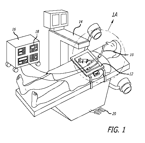
[00181 Figure 1 shows a schematic diagram of the general working environment
of an
example of a system for catheter-based minimally invasive sinus surgery being
used to
perform a sinus surgery on a human patient.
[00191 Figure IA shows a magnified view of region IA of Figure 1 showing a
system
for catheter-based minimally invasive sinus surgery of a human patient.
[00201 Figure lB shows a perspective view of a treatment tray for catheter-
based
minimally invasive sinus surgery of a human patient.
[00211 Figure 2 shows a perspective view of a guide catheter comprising a
plastically
deformable (malleable) region.
[00221 Figure 3 shows perspective view of an embodiment of a guide catheter
comprising a straight hypotube.
[00231 Figure 3A shows a crossection of the guide catheter of Figure 7 through
plane
3A-3A.
[00241 Figure 4A shows a coronal section of the paranasal anatomy showing a
method
of accessing a maxillary sinus ostium using the guide catheter of Figure 2F.
[00251 Figure 4B shows a sagittal section of the paranasal anatomy showing the
method
of Figure 8G to access a maxillary sinus ostium using the guide catheter of
Figure 8F.
[00261 Figure 5 shows a perspective view of a set of devices to dilate or
modify ostia or
other openings.
[00271 Figure 6 shows a perspective view of an embodiment of a balloon
catheter
comprising a sizing balloon and a dilating balloon.
[00281 Figure 6A shows a crossectional view through the plane 6A-6A of Figure
6.
7
WO 2011/082074 PCT/US2010/061850
[00291 Figures 6B - 6D show the various steps of dilating an anatomical
opening using
the balloon catheter in Figure 6.
[00301 Figure 7 shows a perspective view of a cutting device comprising
cutting jaws.
[00311 Figure 7A shows a perspective view of the distal region of the cutting
device of
Figure 7 wherein the cutting jaws are closed as seen from the distal end of
the cutting
device.
[00321 Figure 7B shows a perspective view of one embodiment of the cutting
jaws of
the cutting device of Figure 7.
[00331 Figure 7C shows a crossectional view of the cutting device in Figure 7
through
cutting plane 7C-7C.
[00341 Figure 8A shows a perspective view of an alternate embodiment of a
device
comprising cutting or gripping jaws.
[00351 Figure 8B shows a perspective view of the device of Figure 8A wherein
the
cutting or gripping jaws of the cutting device are in a closed configuration.
[00361 Figure 9A shows a perspective view of an embodiment of an ostium
enlarger
and/or microshaver.
[00371 Figure 9B shows one embodiment of the device of Figure 9A being used to
remove tissue or matter.
[00381 Figure 9C shown another embodiment of the device of Figure 9A being
used to
shave tissue or matter.
[00391 Figure 9D is an exploded view of the device of Figure 9C.
[00401 Figure 10A - 1OC show a suction and snare device and various steps of
employing the device to capture and remove biological substances.
8
WO 2011/082074 PCT/US2010/061850
[00411 Figures 11A - 11C depict a suction and morcellator device and various
steps of
employing the device to capture and remove biological substances.
[00421 Figures 12A - 12C depict a suction grasper device and various steps of
employing the device to capture and remove biological substances.
[00431 Figures 13A - 13C depict a tissue capture suction device and various
steps of
employing the device to capture and remove biological substances.
[00441 Figures 14A - 14C depict a tissue capture device including a capture
vial and
various steps of employing the device to capture and remove biological
substances.
[00451 Figures 15A - 15C depict a capture screen device and various steps of
employing the device to capture and remove biological substances.
[00461 Figures 16A - 16E depict a capture and cutting balloon device and
various steps
of employing the device to capture and remove biological substances.
[00471 Figures 17A - 17D show a spin cutter device and various steps of
employing the
device to capture and remove biological substances.
[00481 Figures 18A - 18C show a back cutter device and various steps of
employing
the device to capture and remove biological substances.
[00491 Figures 19A - 19C show a balloon and cutter device and various steps of
employing the device to capture and remove biological substances.
[00501 Figures 20A - 20C show a spinning shaped cutter device and various
steps of
employing the device to capture and remove biological substances.
[00511 Figures 21A - 21C show a high pressure flushing device and various
steps of
employing the device to capture and remove biological substances.
9
WO 2011/082074 PCT/US2010/061850
[00521 Figures 22A - 22C depict an ultrasonic agitation device and various
steps of
employing the device to capture and remove biological substances.
[00531 Figures 23A - 23D depict a forceps grasper device and various steps of
employing the device to capture and remove biological substances.
[00541 Figures 24A - 24E show various devices for scrubbing and swabbing
devices.
[00551 Figures 25A - 25E depict an approach for treating a paranasal sinus.
WO 2011/082074 PCT/US2010/061850
DETAILED DESCRIPTION
[00561 The following detailed description, the accompanying drawings and the
above-
set-forth Brief Description of the Drawings are intended to describe some, but
not
necessarily all, examples or embodiments of the invention. The contents of
this detailed
description, the accompanying drawings and the Brief Description of the
Drawings do
not limit the scope of the invention in any way.
[00571 A number of the drawings in this patent application show anatomical
structures
of the ear, nose and throat. In general, these anatomical structures are
labeled with the
following reference letters:
Nasal Cavity NC
Nasopharynx NP
Frontal Sinus FS
Frontal Sinus Ostium FSO
Ethmoid Sinus ES
Ethmoid Air Cells EAC
Sphenoid Sinus SS
Sphenoid Sinus Ostium SSO
Maxillary Sinus MS
Maxillary sinus ostium MSO
Mucocyst MC
Eustachian tube ET
Cochlea C
Tympanic cavity TC
Middle turbinate MT
11
WO 2011/082074 PCT/US2010/061850
Inferior turbinate IT
Uncinate UN
[00581 Figure 1 shows a schematic diagram of the general working environment
of an
example of a system for catheter-based minimally invasive sinus surgery being
used to
perform a sinus surgery on a human patient. The human patient is treated by a
working
device 10. Working device 10 may be connected to one or more auxiliary devices
located
on a treatment tray 12. A C-arm fluoroscope 14 provides fluoroscopic
visualization of
anatomical regions during the procedure. An instrument console 16 comprising
one or
more functional modules 18 may also be present. Examples of functional modules
that
can be used with the invention are:
[00591 1. Suction pump for delivering a controlled amount of negative pressure
or
vacuum to a suction device,
[00601 2. Irrigation pump to deliver saline, antibiotic solution or other
suitable
irrigation medium,
[00611 3. Power module to supply power to drills or other electrical devices,
[00621 4. Storage modules for storing instruments, medications etc.,
[00631 5. Energy delivery module to provide radiofrequency, laser, ultrasound
or
other therapeutic energy to a surgical device,
[00641 6. Fluoroscope, MRI, CT, Video, Endoscope or Camera or other imaging
modules to connect or interact with devices used during various diagnostic or
therapeutic
procedures,
[00651 7. Display module e.g. a LCD, CRT or Holographic screen to display data
from various modules such as an endoscope, fluoroscope or other data or
imaging
module,
12
WO 2011/082074 PCT/US2010/061850
[00661 8. Remote control module to enable an operator to control one or more
parameters of one or more functional modules 18,
[00671 9. Programmable Microprocessor that can store one or more operation
settings
for one or more functional modules 18 etc., and
[00681 10. Stabilization device for holding various apparatuses during the
procedure
which may include a stabilization arm, table, clip, intranasal or extranasal
inflatable
support or robotically controlled apparatus,
[00691 11. Rotary drive module for rotating rotatable device such as a drill
or auger
(e.g., a motor having a rotation drive shaft or drive cable attached thereto.
[00701 One or more functional modules 18 maybe connected to the working device
10.
Instrument console module 16 can be controlled by console control means 20,
e.g. a foot
pedal controller, a remote controller etc. Instrument console 16 may be fitted
with wheels
to enable an operator to change the position of the instrument console 16 in
an operating
area. In one embodiment, instrument console module 16 and C-arm fluoroscope 14
are
integrated in a single unit.
[00711 Figure IA shows a magnified view of region IA of Figure 1 showing a
system
for catheter-based minimally invasive sinus surgery of a human patient. In
Figure IA, a
balloon catheter is used as an example of working device 10. Working device 10
has
attachments for a variety of auxiliary devices such as a balloon inflation
syringe 22, a
guidewire 24 and a suction or irrigation tube 26. Working device 10 and the
auxiliary
devices may be detachably attached to treatment tray 12. Treatment tray 12 may
comprise
one or more treatment tray controllers 28 to control one or more treatment
parameters.
Treatment tray 12 may comprise one or more storage modules to store devices
used
during a surgery e.g. irrigation bottles, swabs etc.
[00721 Figure lB shows a perspective view of a treatment tray for catheter-
based
minimally invasive sinus surgery of a human patient. Treatment tray 12
comprises one or
13
WO 2011/082074 PCT/US2010/061850
more device holders 30 to detachably hold devices during the surgery. In one
embodiment, device holders 30 are detachably attached to device holder slots
32 on
treatment tray 12. Thus the position of device holders 30 on treatment tray 12
can be
changed by removing a device holder 30 from a device holder slot 32 and
transferring to
a new device holder slot 32.
[00731 Any diagnostic or therapeutic device disclosed herein may comprise one
or
more malleable regions. For example, Figure 2 shows a perspective view of a
guide
catheter comprising a plastically deformable (malleable) region. Such a guide
catheter
100 can be employed to place a tissue or biological substance removal device
at a target
site in a paranasal sinus. Guide catheter 100 comprises a shaft 102 comprising
a
malleable region 104 located on distal region of shaft 102. Shaft 102 may
comprise
stiffening elements e.g. a braid, hypotube etc. Malleable region 104 may
comprise
malleable metallic tubes, rods (e.g. rods embedded in shaft 102 etc.), wires
etc. Examples
of metals that can be used for constructing malleable region 104 are malleable
stainless
steel, fully annealed stainless steel, copper, aluminum etc. Guide catheter
100 further
comprises a threaded luer 106 located on proximal end of shaft 102. In this
example,
malleable region 104 is located on distal end of guide catheter 100. Malleable
region 104
can also be located on proximal region or any other intermediate region on
shaft 102.
Shaft 102 may also comprise more than one malleable regions. Such a design
comprising
one or more malleable regions can be used for any of the devices mentioned
herein such
as catheters with working elements, guide catheters, guide catheters with a
pre-set shape,
steerable guide catheters, steerable catheters, guidewires, guidewires with a
pre-set shape,
steerable guidewires, ports, introducers, sheaths or other diagnostic or
therapeutic
devices.
[00741 Figure 3 shows perspective view of an embodiment of a guide catheter
comprising a straight hypotube. This structure can also be used to place a
tissue or
substance removal device within a sinus cavity for accomplishing desired
therapies.
Guide catheter 110 comprises a tubular element 112 and a hypotube 114 attached
to the
14
WO 2011/082074 PCT/US2010/061850
external surface of tubular element 112. Suitable materials for constructing
hypotube 114
are Stainless Steel 304, Nitinol etc. In one embodiment, hypotube 114 is
annealed to the
external surface of tubular element 112. Tubular element 112 can be made from
a variety
of materials including Pebax, HDPE etc. Tubular element 112 may comprise a
braid or a
jacket. In an embodiment, tubular element 112 comprises a lubricious coating
115 on its
inner surface. The lubricious coating 115 can be made of suitable lubricious
materials
such as Teflon. In an embodiment, tubular element 112 comprises a bent or
angled region
near the distal end of tubular element 112. The bent or angled region may
enclose an
angle from 0 degrees to 180 degrees. Further this bent or angled region may be
further
bent out of plane to present a compound three-dimension end shape. Hypotube
114 can
be malleable or substantially stiff. A malleable hypotube can be used in
situations where
the guide catheter 110 has to be bent or distorted to optimize its shape to
conform to a
patient's anatomy. Examples of materials that can be used to make a malleable
hypotube
are malleable stainless steel, fully annealed stainless steel, copper,
aluminum etc. A
substantially stiff hypotube can be used in situations where extra support is
needed for
introduction or removal or devices through guide catheter 110. Examples of
materials
that can be used to make a substantially stiff hypotube are Stainless Steel
304, Nitinol etc.
Hypotube 114 may be bent to a two-dimensional or three-dimensional shape.
Distal tip
of tubular element 112 may comprise a radio-opaque marker 111 e.g. a standard
radio-
opaque marker band. The proximal region of tubular element 112 comprises a
threaded
luer.
[00751 Figure 3A shows a crossectional view of guide catheter 110 of Figure 7
through
plane 3A-3A. The crossection of guide catheter 110 shows an outer hypotube 114
enclosing a tubular member 112 which in turn comprises a lubricious coating
115 located
on the inner surface of tubular member 112.
[00761 Figure 4A depicts a coronal section of the paranasal anatomy showing a
method
of accessing a maxillary sinus ostium using guide catheter 100 of Figure 2.
Guide
catheter 100 is introduced through a nostril and advanced in the paranasal
anatomy such
WO 2011/082074 PCT/US2010/061850
that atraumatic tip 104 is located inside or adjacent to a maxillary sinus
ostium MSO.
Proximal bent, curved or angled region 102 allows guide catheter 100 to be
positioned
around the inferior turbinate IT. Similarly, distal bent, curved or angled
region 104
allows guide catheter 100 to be positioned around the middle turbinate MT. A
guidewire
or a suitable diagnostic or therapeutic device may then be introduced through
the lumen
of guide catheter 100 into the maxillary sinus MS. Figure 8B shows a sagittal
section of
the paranasal anatomy showing the method of Figure 8G to access a maxillary
sinus
ostium using guide catheter 100 of Figure 2.
[00771 Figure 5 shows a perspective view of a set of devices to dilate or
modify ostia or
other openings in the sinuses or other body cavities. Guide catheter 200
comprises a shaft
202 comprising a threaded luer 204 at proximal end of shaft 202. Distal end of
shaft 202
comprises a radio-opaque marker band MB to enable the physician to identify
the tip of
shaft 202 in a fluoroscopic image. The distal end of shaft 202 may be
substantially
straight or may comprise one or more bent or angled regions. One or more
distance
markings DM may also be located on the shaft 202. An optional subselective
catheter 806
may also be present in the set of devices. Subselective catheter 206 comprises
a shaft 208
comprising a threaded luer 210 at the proximal end of shaft 208. Inner
diameter of shaft
208 is smaller than inner diameter of shaft 202. Distal end of the shaft 208
comprises a
radio-opaque marker band MB to enable the physician to identify the tip of
shaft 208 in a
fluoroscopic image. Distal end of shaft 208 may be substantially straight or
may comprise
one or more bent or angled regions. One or more distance markings DM may also
be
located on the shaft 208. Working device 212 comprises a shaft 214 comprising
a
working element 216 located on distal region of shaft 214 and a threaded luer
218 located
on proximal end of shaft 214. The working element 216 can be a dilating
balloon or can
be one or more of a combination of suction or irrigation devices, needles,
polypectomy
tools, brushes, brushes, energy emitting devices such as ablation devices,
laser devices,
image-guided devices containing sensors or transmitters, endoscopes, tissue
modifying
devices such as cutters, biopsy devices, devices for injecting diagnostic or
therapeutic
16
WO 2011/082074 PCT/US2010/061850
agents, drug delivery devices such as substance eluting devices, substance
delivery
implants etc.
[00781 In one embodiment of a method, the guide catheter 200 is introduced
into a
patient's body so that distal end of guide catheter 200 is in the vicinity of
an anatomical
opening (e.g. an ostium) of an anatomical region (e.g. a paranasal sinus).
Thereafter, the
guidewire 220 is introduced through guide catheter 200 into the anatomical
region e.g.
the paranasal sinus. If necessary, guide catheter 200 may be removed and the
smaller
subselective catheter 206 may be introduced over guide wire 220 into the
paranasal sinus.
Thereafter, working device 212 is introduced over guidewire 220 into the
paranasal sinus
and a diagnostic or therapeutic procedure is performed by the working device
212. In
another embodiment of a method using the abovementioned set of devices,
subselective
catheter 206 is omitted from the procedure. Additionally, in yet another
approach, larger
guide catheter 200 can be introduced over guide wire 220. The working device
212 is
then introduced over guidewire 220 into the paranasal sinus and a diagnostic
or
therapeutic procedure is performed by working device 212. This method
embodiment
enables a user to introduce larger working device 212 in the anatomical
region.
[00791 Figure 6 shows a perspective view of an embodiment of a balloon
catheter
comprising a sizing balloon and a dilating balloon. The balloon catheter can
be used as a
treatment modality in combination with tissue or biological substance removal.
A
portion of the sizing balloon has been removed to show the dilating balloon
underneath
the sizing balloon. Balloon catheter 250 comprises a shaft 252 and a dilating
balloon 254
located on distal region of shaft 252. Dilating balloon 254 can be made of
suitable non-
compliant materials e.g. polyethylene terephthalate, Nylon etc. Dilating
balloon 254 is
inflated through a first balloon inflation opening 255. Balloon catheter 250
further
comprises a sizing balloon 256 located around dilating balloon 254. Sizing
balloon 256 is
made from a compliant or semi-compliant material such as crosslinked
polyethylene or
other polyolefins, polyurethane, flexible polyvinylchloride, Nylon etc. Sizing
balloon 256
is inflated through a second balloon inflation opening 257. Dilating balloon
254 and
17
WO 2011/082074 PCT/US2010/061850
sizing balloon 256 enclose an inter-balloon volume 258. Figure 6A shows a
crossection
of the balloon catheter in Figure 6 through plane 6A - 6A. Shaft 252 comprises
a
guidewire lumen 260, a first inflation lumen 262 that terminates distally in
first balloon
inflation opening 255 of Figure 14, and a second inflation lumen 264 that
terminates
distally in second balloon inflation opening 257 of Figure 6.
[00801 Figures 6B - 6D show the various steps of dilating an anatomical
opening using
the balloon catheter in Figure 6. In Figure 6B, balloon catheter 250 is
introduced over a
guidewire GW into an anatomical opening 266 to be dilated. Examples of the
types of
anatomical openings 266 that may be dilated by this invention include ostia of
paranasal
sinuses, Eustachian tubes, ostia of lachrymal ducts, etc. Thereafter, in
Figure 6C, sizing
balloon 256 is inflated using an imageable inflating medium. Examples of
suitable
imageable inflating media are saline with a radioopaque contrast agent, carbon
dioxide
gas etc. Distal region of balloon catheter 250 is subsequently imaged using a
suitable
imaging modality such as fluoroscopy or X-rays. This enables an operator to
accurately
estimate the size of anatomical opening 266. Such a balloon catheter is also
suited for
estimating the diameter of the narrowest region in a tubular anatomical region
e.g. a
Eustachian tube prior to performing a diagnostic or therapeutic procedure such
as balloon
dilation. On the basis of information obtained during step 6C, balloon
catheter 250 may
be repositioned and step 6C repeated if necessary. Thereafter, in step 6D,
sizing balloon
256 is deflated. Also in step 6D, dilating balloon 254 is inflated to dilate a
target region in
anatomical opening 266. Thereafter, dilating balloon 254 is deflated and
balloon catheter
250 is withdrawn from anatomical opening 266. In one embodiment, sizing
balloon 256
may be reinflated after a balloon dilation procedure to obtain feedback about
the
performance of the balloon dilation procedure.
[00811 Prior, subsequent or contemporaneously with the implant of a balloon
catheter,
tissue and/or biological substances can be captured or removed from a
treatment site.
Such capture and removal devices can be deployed over a guidewire or can
embody
structure permitting direct placement at the interventional site. Figure 21
depicts one
18
WO 2011/082074 PCT/US2010/061850
approach to a cutting device comprising cutting jaws. Cutting device 300
comprises a
shaft 302 comprising an upper jaw 304 and a lower jaw 306 located on the
distal end of
shaft 302. Proximal region of shaft 302 comprises a scissor-like device with
handles or
other suitable control apparatus 308 that is useable to control the movement
of upper jaw
304 and/or lower jaw 306. Upper jaw 304 and lower jaw 306 are hinged together
so that
they can be opened or closed by scissor handles 308 to bite, grip or cut
tissue. In one
embodiment, the edges of upper jaw 304 and lower jaw 306 are provided with a
series of
cutting teeth. Alternately, the edges of upper jaw 304 and lower jaw 306 may
be provided
with sharp edges, blunt gripping teeth etc. Shaft 302 comprises a lumen 310.
This enables
cutting device 300 to be advanced over an access device such as a guidewire to
access a
target anatomical region. Examples of materials that can be used to construct
cutting
device 300 are stainless steel 304, stainless steel 316, titanium, titanium
alloys etc.
[00821 Figure 7A shows a perspective view of the distal region of the cutting
device of
Figure 7 wherein the cutting jaws are closed.
[00831 Figure 7B shows a perspective view of one embodiment of the jaws of the
cutting device of Figure 7. Upper jaw 304 comprises an upper jaw notch 312. In
one
embodiment, upper jaw notch 312 is semicircular in shape. Similarly, lower jaw
306
comprises a lower jaw notch 314. In one embodiment, lower jaw notch 314 is
semicircular in shape. This design enables a guidewire to pass through a gap
in the distal
end of the cutting device 300 even when upper jaw 304 and lower jaw 306 are
closed. In
another embodiment, a guidewire passes through an opening located on either
upper jaw
304 or lower jaw 306. Upper jaw 304 and lower jaw 306 can also be square,
ovoid,
trapezoidal or circular in shape.
[00841 Figure 7C shows a crossectional view of the cutting device in Figure 7
through
plane 7C-7C. Shaft 302 of cutting device 300 comprises a lumen 310 for an
access device
such as a guidewire. Shaft 302 further comprises one or more pull wires 316
that connect
upper jaw 304 and lower jaw 306 to control apparatus 308. When the control
apparatus
19
WO 2011/082074 PCT/US2010/061850
308 is moved, pull wires 316 transmit the movement to upper jaw 304 and lower
jaw 306
causing them to open or close.
[00851 Figure 8A shows a perspective view of an alternate embodiment of a
device
comprising cutting or gripping jaws. Cutting device 320 comprises a shaft 322.
Distal end
of cutting device 320 comprises an upper jaw 324 and a lower jaw 326 that are
hinged
together at a first hinge 328. Proximal end of upper jaw 324 comprises a first
elongate
member 330 and proximal end of second jaw 326 comprises a second elongate
member
332. The proximal end of first elongate member 330 is connected to a second
hinge 334
which in turn is connected to a third elongate member 336. Proximal end of
second
elongate member 332 is connected to a third hinge 338 which in turn is
connected to a
fourth elongate member 340. The proximal ends of third elongate member 336 and
fourth
elongate member 340 are connected by a fourth hinge 332 to pull wire 344 that
passes
through shaft 322. Figure 8A shows cutting device 330 wherein the upper jaw
334 and
lower jaw 326 are in an open configuration. When pull wire 344 is pulled in
the proximal
direction, fourth hinge 342 is pulled inside shaft 322. This causes the distal
ends of third
elongate member 336 and fourth elongate member 340 to come closer to each
other. This
in turn causes the proximal ends of first elongate member 330 and second
elongate
member 332 to come closer to each other. This in turn causes upper jaw 324 and
lower
jaw 326 close. Similarly, pushing pull wire 344 in the distal direction causes
upper jaw
324 and lower jaw 326 to open. In one embodiment, cutting device 320 comprises
a
spring mechanism located between pull wire 344 and shaft 322 that biases upper
jaw 324
and lower jaw 326 in an open or closed configuration.
[00861 Figure 8B shows a perspective view of the device of Figure 9A wherein
the jaws
of the cutting device are in a closed configuration.
[00871 Figure 9A shows a perspective view of an embodiment of a microshaver or
ostium enlarger device 350. Device 350 comprises a proximal portion 352 and a
distal
portion 353. Proximal portion 352 is hollow and comprises a proximal cutting
surface
WO 2011/082074 PCT/US2010/061850
354 e.g. sharp cutting teeth etc. located on the distal end of proximal
portion 352. Distal
portion 353 comprises a distal cutting surface 356 e.g. sharp cutting teeth
etc. located on
the proximal end of distal portion 353. Distal portion 353 is further
connected to a pull
shaft 358 that encloses a guidewire lumen 360. Guidewire lumen 360 allows
microshaver
350 to be introduced over a guidewire GW into a target anatomy. The region
between
pull shaft 358 and proximal portion 352 encloses a suction lumen 362. Suction
lumen 362
can be used to remove solid debris or liquids from the target anatomy by
suction.
Proximal portion 352, distal portion 353 and pull shaft 358 can be made of
suitable
biocompatible materials such as stainless steel.
[00881 Figure 9B shows a crossection of a paranasal sinus showing one way in
which
the device 350 of Figure 9A may be used to remove tissue or matter. The device
350 is
introduced over a guidewire GW into paranasal sinus 364. The device 350 is
then
positioned such that the tissue or matter is located between proximal cutting
surface 354
and distal cutting surface 356. Thereafter, in this embodiment, pull shaft 358
is pulled in
the proximal direction. This causes movement of distal region 353 in the
proximal
direction with respect to proximal portion 352. This in turn forces
cylindrical distal cutter
356 to be retracted into the interior of the cylindrical proximal cutter 354,
thereby cutting
off or breaking tissue or matter that is captured therebetween. Optionally, in
this
embodiment, the cylindrical distal cutter 356 cylindrical proximal cutter 354
may be
rotated relative to the other to further cut or shave tissue. Also, optionally
in this
embodiment, suction lumen 352 can be used to remove any solid debris or
liquids
generated during the procedure.
[00891 Figure 9C and 9D show an example of another way in which the device 350
may be used-i.e., to shave tissue or matter. Examples of anatomical structures
that may
be shaved by this device 350 include bone, cartilage and soft tissues of
Eustachian tubes,
turbinates, lachrymal ducts, anatomical openings such as ostia of paranasal
sinuses, ostia
of lachrymal ducts, etc. and other regions in the ear, nose, throat or mouth.
As shown in
Figure 9C, in this embodiment, there need not be a proximally moveable pull
shaft 358,
21
WO 2011/082074 PCT/US2010/061850
but rather the distal cutting surface 356 may remain positioned within the
cylindrical
proximal cutting surface 354. The cutting surfaces are positioned adjacent to
the tissue or
matter to be shaved and the cylindrical distal cutter 356 and/or cylindrical
proximal cutter
354 is/are rotated to shave the tissue or matter. Suction may be applied
through lumen
362 to draw the tissue or matter into slots 359 such that it will be shaved by
the rotating
proximal cutter 354.
[00901 Referring now to FIGS. 10A-C, in one embodiment a tissue removal device
380
may include an elongate tubular member 382 and a snare 384. The tissue removal
device
380 may be used to remove tissue from the nasal cavity and/or from within a
paranasal
sinus prior to, subsequent to, or contemporaneous with the use of dilation
catheters such
as those depicted in FIG. 6. In various embodiments, tissue removal device 380
may be
used to remove tissue in one or more paranasal sinuses, in the nasal cavity,
or both. The
elongate tubular member 382 may include a proximal end configured to be
attached to a
device that creates a negative pressure gradient within the tubular member
382. In one
embodiment, the elongate tubular member 382 may further include a balloon or
other
expandable member to allow the device 380 to both remove tissue and dilate an
opening
or other space in the nasal cavity or paranasal sinuses. In one embodiment,
the tissue
removal device 380 may be advanced over a guidewire and/or through an
introducer or
guide catheter, such as those described above in reference to shown FIGS. 2
and 3. In
alternative embodiments, the tissue removal device 382 may be advanced without
the use
of a guide device.
[00911 The elongate tubular member 382 may include an internal lumen sized and
shaped to accept the snare 384. The snare 384 may be moved longitudinally with
respect
to the elongate tubular member 380 so that it can be both advanced beyond a
distal end of
the elongate tubular member 380 and withdrawn completely within the internal
lumen of
the tubular member 380. In various embodiments, the snare 384 may be either a
simple
mechanical loop of material such as a wire or may be equipped to transmit RF
energy. In
22
WO 2011/082074 PCT/US2010/061850
the latter embodiments, a proximal end of the snare 384 may be connected to a
RF energy
transmitting device.
[00921 As shown in FIGS. 10B and 1OC, the tissue removal device 380 maybe
advanced into a patient's nasal cavity 364 (and/or one or more paranasal
sinuses) to
engage tissue or other biological substances. In these and subsequent sets of
figures,
devices are shown removing tissue from the nasal cavity for ease of
illustration.
However, in many if not all embodiments, the devices and methods shown in use
in such
figures may also be used to remove tissue from within one or more paranasal
sinuses. At
some point during or after advancement of the device 380, the snare 384 may be
advanced out of the elongate tubular member 382 and manipulated to snare and
cut a
target tissue or substance. In a purely mechanical approach, the snare 384 can
be placed
about the target tissue and withdrawn to cut the tissue from the sinus cavity.
Alternatively, RF energy can be transmitted to accomplish the severing of
tissue.
Contemporaneously with this severing action or subsequent thereto, a suction
force is
applied via the elongate tubular member 382. The suctioning and withdrawing of
the
snare 384 then accomplishes the capture of the target substances. The device
380 and
severed tissue/substances can then be removed from the interventional site or
further
severing and collection of material can be performed until the site is cleared
as desired.
[00931 With reference now to FIGS. 11A-11C, in a related approach, a therapy
system
400 for removing biological substances from paranasal cavities can include an
elongate,
tubular, suctioning member 402 having a distal end portion configured with a
morcellator
404. Again, balloon dilation or other dilation of paranasal cavities can be
conducted
along with targeted tissue removal. Also, the elongate tubular member 402 is
intended to
be connected to a device that creates a suctioning force within a lumen
running a length
of the elongate tubular member 402. The morcellator 404 can define various sub-
assemblies designed to break down, sever or cut biological substances found in
a
patient's sinuses. In the approach depicted in the drawing figures, the
morcellator 404
can include a plurality of blades that rotate about a central hub. A control
device can be
23
WO 2011/082074 PCT/US2010/061850
attached to the morcellator 404 and extend proximally to an operator so that
rotation of
the morcellator 404 can be effected.
[00941 In use, in combination with or separate from balloon dilation of the
paranasal
cavity, a distal end of the suction and morcellator assembly 400 can be placed
as
previously described within a paranasal sinus adjacent substances targeted for
removal.
Suctioning pressure can then be generated within the elongate tubular member
402 to
begin the substance collection process. The morcellator 404 is then activated
to sever,
cut or chop the targeted substances. The targeted biological substances are
then
withdrawn within the elongate tubular member 402 and can be removed from the
patient's sinuses. This procedure can be repeated as necessary to clean out a
sinus to a
desired degree. Further balloon dilation can also be conducted to fully treat
the sinuses.
[00951 Now turning to FIGS. 12A-12C, another embodiment of a suctioning
tubular
member 420 is disclosed. Independently or along with balloon dilation of a
paranasal
sinus opening or other nasal/paranasal area, the suctioning tubular member can
be used
for therapies for treating the sinuses. As before, the suctioning tubular
member 420 can
further include a balloon or other expandable member for dilating paranasal
sinus
anatomy, or a separate catheter can be employed for this purpose. A proximal
end of the
device 420 is again attached to an assembly that generates a suctioning force.
In the
present approach, a distal end of the suctioning tubular member 420 is
configured with a
single limb with a plurality of holes 422 formed therein to adhere to tissue
reversibly
using suction. As shown in the figures, this relatively less traumatic
approach to tissue
manipulation can be used to capture and remove tissue 365 or other substances
from
sinus and/or nasal cavity anatomy.
[00961 In yet another related approach (FIGS. 13A-13C), a tissue capture
suction
device 430 having a generally elongate tubular body structure and a distal end
including a
cutting edge 432 is contemplated to sever, capture or remove tissue from sinus
anatomy.
This assembly as well can be advanced over a guidewire and/or within a guide
catheter or
24
WO 2011/082074 PCT/US2010/061850
can itself define a guide catheter. Moreover, this device can be used with or
independently from a balloon catheter or other structure for dilating
paranasal sinus
and/or nasal cavity anatomy, or expandable structure can be incorporated
directly into the
tubular body.
[00971 As shown, the cutting edge 432, which extends a full circumference of
the
tubular body, is defined by a sharp angle between an internal luminal wall of
the tubular
capture suction device 430 and an outer surface thereof. Various other
approaches to
cutting surfaces are also contemplated such as sharp edges extending less than
a full
circumference of the distal tubular portion. The tissue capture suctioning
device 430
further includes a filter 434 for registering captured material within the
device.
[00981 In use, separate or contemporaneously with balloon or other sinus
dilation, the
tissue capture suctioning device 430 is placed at the intervention site
adjacent substances
to be collected. By way of a connection to a suction subassembly, suction
force is
applied while the cutting edge 432 is manipulated to engage and sever the
substances
targeted for removal. When the device dislodges the substances target for
removal, the
suctioning force draws the substance within the elongate tubular member, the
filter 434
operating to retain the substance in place.
[00991 Alternatively, as shown in FIGS. 14A-14C, a tissue capture device 450
can
include an elongate tubular member 452 terminating with a cutting surface 454
as well as
a capture subassembly 456 with a vial 458 attached to a proximal end of the
tubular
member 452. For ease of manipulation, the elongate tubular member 452 can
rotate with
respect to the capture subassembly 456 to engage and sever targeted biological
substances. Although this embodiment shares features with the immediately
preceding
embodiment both in structure and use, here a filter is configured within the
capture
subassembly 456 to effect registering captured material. In this way, captured
material
can be displaced from the interventional site, and a larger volume of material
can be
collected.
WO 2011/082074 PCT/US2010/061850
[001001 A capture screen device 470 such as that depicted in FIGS. 15A-15C can
also be
employed to sever and collect biological substances targeted for removal from
the
paranasal sinuses. As with the previously described embodiments, this device
can be
used while applying a suctioning force as the capture screen device 470 is
used to collect
targeted tissues independently of the use of suction. Moreover, as before,
this device can
incorporate a balloon or other dilation of sinus anatomy and it can form part
of a guide
catheter and/or be deployable within the same or over a guidewire. The
presently
contemplated capture screen devices 470 includes an expandable and collapsible
screen
472 that is longitudinally translatable within a generally tubular tube 474.
Again, the
tube 474 can be attached to a suctioning subassembly as desired. Moreover, a
balloon
(not shown) can be configured within the screen 472 to aid in expanding the
screen or
contribute to dilation of sinus anatomy.
[001011 In use, the capture screen device 470 is placed within a nasal cavity
or paranasal
sinuses at the interventional site. Once placed as desired, the screen device
472 is
advanced beyond the distal end of the tubular member 474 and either permitted
to self
expand or is expanded by way of opposing motion of members defining the screen
472
(such as a pull wire attached to a distal end of the screen, not shown).
Material to be
severed is captured between crossing struts 476 of the screen structure 472
when the
screen 472 is expanded. Both manipulation of the screen 472 and/or the
subsequent
withdrawal and collapse of the screen within the tubular member 474
accomplishes
cutting the targeted biological material from within the sinus and collection
of the
material within an interior of the screen. The treatment is completed upon
removal of the
screen loaded with the collected material from the interventional site.
Multiple collection
steps can be repeated as necessary to complete the desired treatment.
[001021 Turning now to FIGS. 16A-16E, another approach to therapies involving
biological tissue or substance capture and removal is presented. A balloon
catheter 490
including a balloon 491 having an outer surface configured with cutting
elements is
contemplated for this purpose. Such devices can be advanced over a guidewire
and
26
WO 2011/082074 PCT/US2010/061850
within a guide catheter as disclosed above and can further be used along with
suctioning
or other capture approaches to remove severed tissue along with or independent
from
independent balloon dilation of the sinus anatomy. In one approach, the
cutting balloon
490 can include one or more blades 492 extending longitudinally along the
balloon body
491 (FIG. 16A). The blades can also assume a scooper design 494 or a helical
pattern
496 as shown in FIGS. 16B and 16C. To provide treatment at an interventional
site, the
balloon catheter 470 is expanded to fully expose the blades 492, 494, 496.
Manipulating
the balloon 490 so that the blades 492, 494, 496 engage and sever the targeted
tissue 365
results in dislodging the tissue from walls defining the paranasal cavity. The
severed
tissue 365 can then be subsequently removed by flushing or by employing a
suctioning
member (not shown).
[001031 In an alternate approach, the severing of target tissue can be
achieved employing
a spin cutter device 500 (See FIGS. 17A-17D). Here as well, the spin cutter
device 500
can be employed with a dilation catheter for opening paranasal sinus cavities
and the
device can be advanced within a guide catheter and/or over a guidewire. As
shown, the
spin cutter device 500 includes an elongate generally cylindrical member 502
having an
external surface configured with cutting blades 504 having a curved, rolled
profile
defining a tissue retention feature. Once placed as desired within sinus
anatomy, the spin
cutter 500 is rotated so that the cutting blades 504 both cut and capture
tissue within its
rolled structure. The device can be reused as necessary and then withdrawn
from the site
employing a sheath so as to avoid trauma to tissue in the area.
[001041 Yet further approaches to tissue collection and removal are depicted
in FIGS.
18A-18C and 19A-19C. Such further approaches can be conducted independently
from
or in combination with one or more of balloon dilation of sinus or nasal
cavity anatomy,
suctioning pressure, over guidewire advancement and guide catheter
introduction. As
shown in FIGS. 18A-18C, a back cutter device 520 can be employed to capture
biological
substances 365 targeted for removal from sinuses. The back cutter device 520
can
include a cone 522 supported on a longitudinal member 524, each of which are
27
WO 2011/082074 PCT/US2010/061850
translatable with request to a generally tubular collection sleeve 526. In one
embodiment, the longitudinal member 524 slides within an interior of the
sleeve 526 and
the cone 522 is sized to be received within a distal end of the sleeve 526. It
is
contemplated that one or both of the proximal end of the cone 522 and a distal
end of the
sleeve 526 can include structure for cutting biological substances typically
found within
sinuses. In this regard, as before, structure defining both the cone 522 and
sleeve 526 can
include a sharp angle about the center or a portion of a circumference of the
cone 522 and
sleeve 526. To achieve dissection, targeted matter 365 can be arranged between
the cone
522 and the sleeve 526 and the longitudinal member 524 can be rotated to cause
the
cutting surface of the cone 522 to cut the targeted matter 365. Additionally,
the sleeve
526 can also be rotated to cut the targeted matter 365. Once it is believed
that a sufficient
dissection has occurred, the longitudinal member 524 can be drawn proximally
to capture
dissected material between the cone 522 and sleeve 526.
[001051 In a related embodiment (FIGS. 19A-19C), a balloon and cutter device
540 is
configured to cut and capture biological tissue 365 in paranasal sinuses
and/or the nasal
cavity. Here, the device 540 includes a distal portion that is configured with
both a
laterally extending expandable balloon as well as an open window 544
positioned on an
opposite side of the device from the balloon 542. Configured within the window
544 is a
cup-shaped cutter 546, a proximal end of which is connected to a manipulation
member
548 extending to an operator. The balloon portion 542 of the device can be
employed to
open ostia or other spaces within the sinuses or to anchor the device for
tissue collection.
Tissue collection can occur by placing the window 544 over tissue or other
substances to
be cut and removed. The cup-shaped cutter 546 can then be rotated and/or
advanced
against the material to cut and capture the same. The captured material can
then be
removed from the site by withdrawing the balloon and cutter device from the
patient.
[001061 A spinning shaped cutter device 560 such as that depicted in FIGS. 20A-
20C
also can be used as previously described to access and then be placed adjacent
tissue
identified for removal from the sinuses. This device is provided with a
generally tubular
28
WO 2011/082074 PCT/US2010/061850
body 562 sized to receive a scored, elongate member 564, the terminal distal
end of
which includes a shaped cutter 566. In one approach, the cutter 566 is highly
flexible and
through the manipulation of the elongate member 564, the cutter 566 is rotated
to cut
tissue. The depth of advancement of the shaped cutter 566 is monitored by
noting the
position of the markings on the elongate member 564 relative to a proximal end
of the
tubular body 562. Similar scoring of other embodiments of disclosed therapy
devices can
be employed to monitor device placement. Additionally, direct or remote
viewing
technologies such as endoscopy and/or fluoroscopy can be used to aid in tissue
dissection
and capture.
[001071 Yet another approach to sinus therapy (FIGS. 21A-21C) can involve
employing
a high pressure fluid delivery system 580 to dislodge material from within a
patient's
nasal cavity 364 and/or paranasal sinus. The system 580 can also be equipped
to suction
dislodged material from the therapy site through a tubular body 582 as well as
a balloon
584 that can be used to stabilize the system or to dilate ostia or other sinus
cavities.
[001081 The therapy device 600 can further be defined by a generally tubular
member
602 with a plurality of openings 604 formed therein (See FIGS. 22A-22C). In
this
application, where it has been found to be difficult to cut through hard
tissue or bone, a
cutter 606 is configured to be responsive to or apply ultrasonic spinning or
other oscillary
motion to improve cut-ability. That is, motion such as spinning or vibration
can induce
micromotions that help eliminate friction and further augment cutting ability.
The cutter
600 can further be withdrawn as desired to cut tissue adjacent or extending
within the
holes 604 formed in the device body 602.
[001091 In still yet another approach (FIGS. 23A-23D), in combination with
balloon
dilation of sinus anatomy, a forceps grasping device 620 is provided to engage
and
remove tissue from within a paranasal sinus, a paranasal sinus opening and/or
a nasal
cavity. The device 620 can include a reusable handle 622 and replaceable
grasper
structure 624. The device can also be entirely disposable or reusable.
Moreover, the
29
WO 2011/082074 PCT/US2010/061850
forceps grasper 620 device may be sized and shaped to be placed through a
guide
member (not shown). In any event, proximally located finger receptacles 626
are
conveniently placed so that tissue extraction can be accomplished remotely.
[001101 Various approaches to mechanically scrubbing, cleaning and swabbing
paranasal cavities are presented in FIGS. 24A-24E. Thus, rather than using
sharp blade-
like objects, cotton swabs 630 (FIG. 24A), cloth members 632 (FIG. 24B) or a
fine brush
634 are contemplated for treating paranasal sinuses. Also contemplated is the
use of a
wire scrubber 636 depicted in FIG. 24D. For each of these objects, the
scrubbing or
swabbing members can be advanced through a sheath 640 and permitted to self-
expand to
a configuration suited for effectively engaging surfaces internal to the
paranasal sinuses.
Dislodged material can be withdrawn from the therapy site directly by the
swabbing/ scrubbing device as well as via other disclosed methods (i.e.
suctioning).
[001111 The removal device may include any of those described above. In
various
embodiments, the removal device may be advanced through a guide, as shown, or
may be
advanced on its own, without using a guide. In various embodiments, an
endoscope may
be used to view all or some of the procedure. In one embodiment, a variable
degree of
view endoscope may be used, such as a swing prism endoscope described in U.S.
Pat.
App. Serial No. 12/502,101, entitled "Swing Prism Endoscope," the full
disclosure of
which is hereby incorporated by reference.
[001121 In some embodiments, the tissue removal device may include a balloon
dilation
catheter, for example mounted on a catheter shaft that houses a tissue cutter.
Thus, in
some embodiments, the dilating and tissue removal functions may be achieved by
the
same device. In some embodiments, this combination device may be advanced over
or
through a guide, while in alternative embodiments it may not require a guide.
[001131 The method shown in Figs. 25A-25E may also be applied to other
paranasal
sinuses, such as the maxillary, sphenoid and ethmoid sinuses. Although the
ethmoid
sinuses typically do not have one discrete, natural opening as the other
sinuses do, some
WO 2011/082074 PCT/US2010/061850
combination of dilation and tissue removal may be used in some embodiments to
treat the
ethmoid sinuses and/or areas of the nasal cavity such as the osteomeatal
complex. Here,
a balloon catheter 650 is advanced through a guide catheter 652 to within an
ostium or
outflow tract 653 leading to a frontal sinus 654. The balloon 656 of the
balloon catheter
is expanded (FIG. 25B) to open the ostium or outflow tract. The balloon
catheter 650 is
then removed leaving the guide catheter in place (FIG. 25C). Bone fragments or
other
biological substances 660 may remain at the site. Thus, a tissue removal
device 670 such
as those described above can be advanced to the site through the guide 652
(FIG. 25D).
Once there, the fragments can be removed to thereby leave an expanded, clear
outflow
tract and ostium.
[001141 In various alternative embodiments, the devices, systems and methods
described
above may be used for diagnosing or treating other conditions caused by
narrowing or
blockage of structures in the ear, nose, throat or mouth. Also in various
embodiments,
devices described herein such as catheters may comprise one or more lumens
such as
end-to-end lumens, zipper lumens, rapid exchange lumens, parallel lumens
surrounded by
a jacket, and the like.
[001151 The above description provides a number of examples and embodiments,
but
various additions, deletions, alterations and modifications may be made to
these
examples and embodiments without departing from the intended spirit and scope
of the
present invention. For example, any element or attribute of one embodiment or
example
may be incorporated into or used with another embodiment or example, unless to
do so
would render the embodiment or example unsuitable for its intended use. All
reasonable
additions, deletions, modifications and alterations are to be considered
equivalents of the
described examples and embodiments and are to be included within the scope of
the
following claims.
31