Note: Descriptions are shown in the official language in which they were submitted.
CA 02785925 2012-06-28
WO 2011/079338 PCT/AT2010/000490
1
DEVICE FOR THE MEASUREMENT OF INDIVIDUAL FARM ANIMAL DATA
The invention concerns a device for measuring at least one physiological
parameter of a farm
animal's organism, whereby such device can be placed in the gastro-intestinal
tract of the
farm animal and contains at least one sensor for measuring at least one
physiological
parameter of the farm animal's organism, at least one transmitter with antenna
for the
wireless transmission of information, at least one control unit for
controlling the device, and
at least one power supply device for supplying the device with power.
The invention further relates to a system, comprising at least one of the
aforementioned
devices and a base station, the base station and the device communicating with
each other
via a wireless procedure. A base station may for example be a data processing
unit which
communicates with one or several devices by means of antennas and processes
and stores
the transmitted information.
Livestock farming, in particular of dairy cattle, is currently subject to
structural changes,
especially in Europe with a tendency to large-scale farming. In this context,
herd
management turns out to be increasingly difficult, e.g. when it comes to
controlling the
health of individual animals or to allocating feeds. With increasingly large
herds, symptoms
of illness M individual animals are frequently not detected in time, and
customized feeding
is hardly possible. In order to ensure both appropriate feed and care for the
animals and to
make farming economically viable, it is enormously important for farmers to
keep
themselves precisely informed about their animals' state of health.
Let us take the example of cattle farming: especially in high-yield dairy
cattle herds, e.g.
Subacute Ruminal Acidosis (SARA) is a widespread problem, and mostly
cumulative in a
herd. The negative effects of SARA on the livestock's health are multifarious
and represent a
central factor that reduces production figures in cattle farming. For various
reasons, SARA is
a pathological and disease-causing state that is not always diagnosed
accurately. The lack of
simple and specific diagnostic methods, and/or the proneness of applicable
diagnostic
methods to mistakes have led to a situation where the diagnosis so far is
usually made
indirectly and retrospectively (e.g. via the fat content of the milk, fat
protein ratio) and/or
based on secondary clinical symptoms (e.g. thin, mushy excrement containing an
increased
percentage of undigested elements).
In order to solve these problems, devices were developed that can be placed
directly in the
gastro-intestinal tract of livestock in order to measure physiological data.
For example
DE 199 01 124 Al describes such a device, consisting of a probe in bolus form,
which is
2
inserted into the gastro-intestinal tract of cattle, and of a controllable
monitoring device,
which communicates with the probe via a wireless procedure. A bolus form is
commonly
understood to be a pill form, thus essentially an object with an oval cross-
section along its
longitudinal axis. The probe contains sensors for the measurement of one or
several different
physiological parameters, such as pressure, temperature, conductivity, pH
value, or
ammonia content in the gastro-intestinal tract.
Similar solutions are described in US 2004/0133131 Al, WO 01/13712 Al, US
5,984,875,
WO 2006/046057, and GB 2455700. US 6,694,161 Bl additionally shows an
illustrative
embodiment, in which the pH sensor and a transmitter located outside the
animal are
connected via a cannula needle.
The said devices are mostly fragile devices that are only insufficiently
protected from heavy
mechanical influence. Damage during their utilization caused by sharp-edged
individual
parts of harmful substances may thus jeopardize the health of the farm animal
in question.
It is thus an aim of the invention to come up with a device that overcomes the
said
disadvantages of prior art.
Certain exemplary embodiments can provide a measuring device for the
measurement of at
least one physiological parameter of a farm animal organism, wherein the
measuring device
is placeable in the gastrointestinal tract of the farm animal and comprises
the following
components arranged within an interior of a casing: at least one sensor for
the measurement
of at least one physiological parameter of the farm animal organism; at least
one transmitter;
an antenna provided on the at least one transmitter for wireless transmission
of information;
at least one control unit for control of the measuring device; at least one
power supply device
for the measuring device; and wherein the casing further includes: a hollow
protective guard
covering the at least one power supply device in order to ensure protection
from mechanical
impact; and wherein the protective guard is sufficiently strong enough to
withstand being
bitten or chewed by the farm animal organism and to continue to cover and
protect the at
least one power supply device; wherein the antenna is located outside of the
protective
guard; and wherein the protective guard serves both as bite protection and as
an additional
CA 2785925 2019-01-29
2a
weight, and wherein the measuring device is arranged such that an outermost
region of the
measuring device comprises the casing; and the protective guard is located
within the
interior of the casing, and wherein the components to be protected are located
within an
interior of the protective guard.
According to the invention the identified problem is solved by a device of the
initially-
mentioned kind, wherein a hollow protective guard, covering at least the power
supply
device to protect it from mechanical impact, is arranged inside the casing.
Thanks to the invention it is possible to ensure real time livestock
monitoring. Due to the
wireless transmission of the information registered by the device cost-
effective integration
into similar or existing feeding systems which are also based on wireless
procedures is
possible. In such a case transmission is ensured by the transmitter, however,
a transceiver
device may also be provided for, which has the advantage of both transmitting
and receiving
data.
On the one hand, the protective guard protects the sensitive parts of the
device from
mechanical impact, for example from bites in case the device lands in the
mouth or between
the teeth of livestock. At least the power supply device, which frequently
contains harmful
substances, should be covered by the protective guard, in order to protect the
animal from
injury, e.g. from poisoning, in case of excessive mechanical strain to the
device.
On the other hand, the protective guard allows for increase and/or
customization of the
weight - i.e. the specific weight - of the device, in order to ensure optimal
positioning of the
CA 2785925 2019-01-29
CA 02785925 2012-06-28
WO 2011/079338 PCT/AT2010/000490
3
device in the gastro-intestinal tract of the farm animal. This enables proper
data acquisition
by the at least one sensor.
In addition, if the protective guard is manufactured from a conductive
material, it is possible
to improve the electromagnetic conditions for the device (or the antenna of
the transmitter,
respectively), in order to positively influence the radiation pattern of the
antenna.
Advantageously, the protective guard does not entirely cover the elements to
be protected,
but is executed in such a way that they may be inserted into the protective
guard and
removed if necessary. The protective guard thus ideally has cylinder form,
with a circular or
polygonal cross-section. Ideally, the bottom and cover surfaces are left open.
In the following
description, the term polygonal cross-section is intended to mean a polygonal
cross-section
which may be triangular, quadrangle, hexagonal, octagonal or designed to have
more angles.
Due to the regular design, an improved reception and distribution of
mechanical impacts is
achieved and damage to the elements covered by the protective guard is
avoided.
In one variant of the invention, the protective guard is made of metal.
Possible materials are
for example steel or brass, which are easy to process and available at low
price, thus
permitting a time- and cost-saving production of the device according to the
invention. A
condition for its utilization is the aforementioned requirement of resistance
against
mechanical impact. For the above-mentioned reasons, the choice of the material
also depends
upon the specific weight of the material used and upon its effect on the total
weight of the
device.
In another variant of the invention, the protective guard covers not only the
power supply
device, but also the transmitter and the control unit, and thus protects
further sensitive parts
of the device from damage. At the same time, the enlarged surface of the
protective guard
may lead to an increased weight of the device. As mentioned above, the
protective guard is
preferably designed in such a way as to enable easy insertion and, if
necessary, removal of
the parts to be protected. If the protective guard is executed in cylinder
form, this may be
achieved by leaving open the bottom and cover surfaces.
Basically different antenna types may be used - for example the antenna may be
executed as
dipole or directional antenna. Also the dimensioning is more or less left to
discretion and
may be X/2, for instance. However, it is important to consider the limited
space in the casing
of the device. The length of the transmitter antenna should preferably be
dimensioned to XJ4
of the used frequency.
CA 02785925 2012-06-28
WO 2011/079338 PCT/AT2010/000490
4
The transmitter transmits information via frequencies in the range of 20 MHz
to 1 GHz. In a
variant of the invention the transmitter transmits information via frequencies
ranging from
300 MHz to 450 MHz. In Europe a frequency of 433 MHz is used, for instance.
For
applications in the USA a frequency of 315 MHz may be used. Furthermore the
use of ISM-
radio bands (Industrial-, Scientific- and Medical band) in the range of 868
MHz or 915 MHz
is possible.
Good results are achieved with antennas in meander form with at least one
loop. Meander
form is intended to mean a form consisting of one or more interconnected loops
in serial
arrangement. The term meander derives from the bends in a sinuous watercourse.
The loops
of the meandered antenna may in this case be angular or circular. The antenna
is
dimensioned according to the frequency used. The meander form enables the use
of long
antennas in a small space. The meandered antenna has the omnidirectional
radiation pattern
that is required for the proper functioning of the device and is easy to tune,
a property which
is for example necessary for protective guards made of metal which, together
with the power
supply unit, influence the radiation pattern.
In one variant of the invention, the device is equipped with at least one
switch which is
connected to the control unit and may be actuated from outside the device. The
switch serves
for example for activating and/or deactivating the device. Basically the
switch may be of any
kind, as long as it withstands the conditions under which the device is used.
In the present
case, this would be the acid environment of the gastro-intestinal tract of a
farm animal, such
as a cow.
The switch may be configured as a magnetic switch (eg. a Reed-switch) which is
located
inside the measuring device 3. Here, the term magnetic switch denotes a switch
that can be
switched by a magnetic field. In the present case the measuring device 3 may
be activated (or
deactivated) by applying a magnetic field at a certain position of the
measuring device. A
Reed-switch basically consists of two contacts which are arranged in vacuum or
inert gas;
when a magnetic field (permanent magnet or electromagnet) is applied the
contacts are
brought into contact and, hence, close a circuit.
In another variant of the invention, the switch is executed in form of at
least two contacts
connected to the control unit, which protrude from the device through openings
in the
casing, whereby the control unit activates the device by short-circuiting the
contacts. This
means that the control unit activates the measuring device when the contacts
are short-
circuited. This may be achieved by providing a start-up circuit with two
MOSFETS. The first
MOSFET is connected to the contacts, and by short-circuiting the contacts the
second
MOSFET is actuated so that the battery load is switched over to the control
unit and from
CA 02785925 2012-06-28
WO 2011/079338 PCT/AT2010/000490
there to the areas necessary for the functioning of the measuring device. The
short-circuiting
of contacts can be achieved, for example, by providing a support for inserting
the device,
whereby its insertion would cause the short-circuiting of the contacts.
In addition, the device comprises at least one storage unit for data storage.
This storage unit
advantageously is a conventional storage chip (EEPROM - electrically erasable
prograirunable read-only memory); however other storage devices such as SD
cards, flash
memories or the like are also possible. When the device is provided with a
RFID transponder,
a storage unit of the RFID transponder may be used for data storage.
The goal of the invention is furthermore achieved by using a system as
initially mentioned,
which comprises at least one of the above-cited devices and at least one base
station.
In the following, the present invention is described in more detail with
reference to the
drawings, which show:
Fig. 1 a cow with a device according to the invention placed in its gastro-
intestinal tract,
Fig. 2 a plan view of a sectional view of the device according to the
invention,
Fig. 3 a side view of a sectional view along the line A-A in Fig. 2,
Fig. 4 a front view of a sectional view along the line B-B in Fig. 3,
Fig. 5 an exploded view showing the individual parts of the device according
to the
invention, and
Fig. 6 a schematic drawing of the components of the device.
It should be appreciated that the invention is not restricted to the following
embodiments
which merely represent one of the possible implementations of the invention.
Furthermore, it
is noted that the representations in the figures are only schematic for the
sake of simplicity.
Fig. 1 shows the sectional view of a cow 1, whereby the cow 1 in this case
only serves as an
example of a farm animal in whose gastro-intestinal tract the device can be
inserted.
Examples for other suitable livestock are e.g. sheep, goats, and wild
ruminants, such as red
deer.
CA 02785925 2012-06-28
WO 2011/079338 PCT/AT2010/000490
6
The feed ingested and masticated by the cow 1 ends up in the stomach of the
cow 1, e.g. in
the rumen or reticulum 2. The reticulum 2 is part of the cow's 1 stomach,
located before the
rumen. From the reticulum 2, the ingested feeds either move forward into the
rumen, or
backward into the mouth of the cow 1 for rumination.
The feeds in the stomach of the cow 1 roughly can be divided into three
phases: at the top is
the gaseous phase containing CO2 and methane (CH4). In between is a solid
phase, the so-
called "fiber mat", containing pre-digested hay, silage grass etc. In the
lower portion is the
rumen fluid, consisting of liquids, such as acids, microbes, saliva, water,
and masticated
material. Measuring the physiological parameters of the stomach contents
allows one to
draw conclusions about possible effects and/or conclusions as to the animal's
state of health
- whenever the pH is low, e.g. rumen acidosis may occur. The measuring device
3 according
to the invention is thus placed within the gastro-intestinal tract of the
animal - i.e. in the
present example in the area of the reticulum 2 of the cow 1 in order to
capture physiological
data of the stomach.
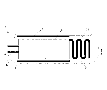
Figs. 2, 3 and 4 show the measuring device 3 according to the invention in
different sectional
views. The measuring device 3 is inserted into the gastro-intestinal tract of
a ruminating farm
animal by appropriate means and remains there. To introduce the measuring
device 3, e.g. a
balling gun common in livestock farming is used.
Fig. 2 shows a plan view of a section along the longitudinal axis of the
inventive measuring
device 3, hereinafter also referred to as bolus, whereby the same reference
sign is used as for
the measuring device 3.
The casing 4 of the bolus 3 has a cylinder form with rounded edges of large
radiuses,
whereby external burrs should be avoided in order to minimize the risk of
injury for the
animal. The materials for the casing 4 are preferably acid-proof, impact-
strong plastics,
which ideally comply with the rules of the American Food and Drug
Administration (FDA).
The casing 4 should not break irregularly below a certain load threshold. When
choosing the
plastic to be used the acid environment of the animal's gastro-intestinal
tract should be taken
into account.
The casing 4 is lockable and can, for this purpose, be composed of several
parts, for example
of two or three interlockable parts (see Fig. 5). The casing 4 contains the
devices necessary for
the measuring of physiological parameters. These devices are arranged on a
printed circuit
board 5 (PCB). The exact arrangement is not illustrated in Fig. 2, since a
number of
arrangements are possible which are well known to the person skilled in the
art. Reference is
CA 02785925 2012-06-28
WO 2011/079338 PCT/AT2010/000490
7
made to only one area 6 of the printed circuit board 5 in which the individual
components
are located.
Fig. 6 shows a schematic drawing with the components of the inventive device 3
and their
connections. The components are located in a casing 4. The casing comprises a
control unit 7
for controlling the measuring device 3. This may for example be achieved using
an
adequately programmed micro-processor. The control unit 7 controls and
processes data
from the sensors 8, 8'. A storage unit 16, for example a storage chip or an SD
card, may be
provided for data storage. At least one sensor 8, 8' is to be provided,
however, more than
two sensors may also be used. The sensors 8, 8' measure parameters of their
surroundings
such as pH and temperature. However, also sensors for measuring glucose,
volatile fatty
acids (especially mixed fatty acids), acetate, propionate, butyrate, and
lactate may be suitably
provided for. The sensors 8, 8' are mounted in such a way as to be able to get
in contact with
the environment of the measuring device 3, for example through openings (not
illustrated in
the figures).
The data are processed by the control unit 7. Via a transmitter device 9,
equipped with an
antenna 10, the data are transmitted wirelessly, for example to a base station
located outside
the animal. Preferably, the transmitter 9 is designed as transceiver device 9
which is able to
both transmit and receive data. Hence, the term transceiver 9 will be used in
the following.
Via the antenna 10 and the transceiver 9 it is possible to influence the
control unit 7 from the
outside, for example in order to modify the internal programming. The antenna
10 may be
executed in various ways, for example as helical antenna or corkscrew antenna,
or as ceramic
and/or patch antenna.
The transceiver 9 operates in the frequency range 20 MHz to 1 GHz. Frequency
bands that are
frequently used in similar applications range from 300 MHz to 450 MHz. The
frequency
433 MHz is used in Europe, for instance. For an application in the USA the
frequency
315 MHz may be used. However, other useable ISM-radio bands (Industrial,
Scientific and
Medical band) lie in the range of 868 MHz or 915 MHz. Also the frequency 27
MHz may be
used.
The transceiver 9 may be realized as RFID transponder is also possible. In
this case,
depending on its design variant the RFID transponder, may be contain an
antenna, a
switching circuit for the transmitting (and receiving) of data, a circuit for
controlling the
transponder as well as a memory, for example in form of a tag. The switching
circuit for
transponder control writes data into the memory (e.g. the tag). In a special
design, this
switching circuit may be located outside the RFID transponder, in the present
case for
CA 02785925 2012-06-28
WO 2011/079338 PCT/AT2010/000490
8
example as part of the control unit 7 on the printed board 5. The RFID
transponder is then
read out via a stimulation by means of a high-frequency alternating field. In
such a case the
RFID transponder is to be adequately arranged on the printed circuit board 5.
When using an RFID transponder, data are transmitted within a frequency range
of 128 kHz
(long-wave range) up to 13,56 MHz (short-wave range), or within a range of 865-
869 MHz
(European range) up to 950 MHz (US American and Asian frequency ranges).
Frequency
may vary from one region to the other.
As far as construction size and other specifications are concerned it is
possible to choose
from a number of well-known solutions.
The power supply device may be a battery 11 or an accumulator.
The antenna 10 in Fig. 2 is executed as meandered antenna. It consists of
several loops of an
appropriate carrier material, which are arranged on the level of the printed
circuit board 5.
Antenna 10 in the mentioned design enables an optimal compromise between the
radiation
pattern in the vertical and horizontal planes of polarization, the necessary
adaptation and
cost-effective production. The meandered antenna can be optimized for a direct
connection
of the antenna base to the printed circuit board 5 so that no additional
adaptation is
necessary, which further reduces production costs.
Fig. 3 shows a lateral cross-section of the measuring device 3 along the line
A-A in Fig. 2. It
shows that the battery 11 is arranged below the printed circuit board 5 within
the casing 4.
The illustration of battery 11 and its arrangement is, however, only given as
example; it may
also be arranged in any other form according to the commonly available battery
or
accumulator forms.
The power supply units used, for example lithium batteries, generally contain
substances
that are potentially harmful for livestock. Therefore the inventive device 3
is designed to
contain a hollow protective guard 12 covering at least the battery 11 in order
to protect it
from mechanical impact. Such impact may for example occur when the cow 1
regurgitates
the measuring device 3 back up into its mouth together with the feed to be
ruminated and
then bites into the measuring device 3.
Preferably, the guard 12 is executed in cylindrical form. In the pictured
embodiment the
cylinder has a circular cross-section (see fig. 4), however the cross-section
may also have a
polygonal form. Ideally, both the top and bottom planes are open so that the
appliances to be
protected are easily inserted into the device. The protective guard 12 may be
made from any
CA 02785925 2012-06-28
WO 2011/079338 PCT/AT2010/000490
9
material that resists high mechanical impact, for example from plastics such
as KevlarTM, or
Metals, such as brass or similar metals.
In the illustrated embodiment, the protective guard 12 surrounds not only the
power
supply unit 11 but also most of the printed circuit board 5 with the
aforementioned
components (for example also the aforementioned RFID transponder). Preferably,
the
antenna 10 is arranged outside the protective guard 12 - in order to minimize
the impairing
of the radiation pattern, which is considerable, especially where a metallic
material is used
for the protective guard 12. Fig. 4 shows a variant of the invention in a
dotted outline, in
which a protective guard 12' surrounds only the battery 11. In such a case,
the protective
guard 12 of a higher diameter may be omitted - it is however possible to
provide for a
combination of a protective guard 12' for the battery and another bigger
protective guard 12
surrounding it.
The protective guard 12 serves both as protection from mechanical influence
("bite
protection") and as additional weight, providing the device 3 with sufficient
density to
ensure that it remains in a location within the gastro-intestinal tract which
is favorable for
data reception by the sensors 8, 8'. If the protective guard 12 is made of
metal, it may
improve the radiation pattern of antenna 10 by altering the electromagnetic
near field of the
antenna 10.
In addition to its "bite protection" function, the protective guard 12
contributes to the weight
of device 3. The weight, i.e. the specific gravity (density) of the measuring
device 3 is highly
important for the proper positioning of device 3 within the gastro-intestinal
tract of the farm
animal in question. Thus the weight of the entire measuring device 3 may be
influenced by
the material selected for and the thickness of the protective guard 12. For
example it is also
possible to vary the thickness of the protective guard 12 lengthwise.
In order to further increase the weight of the measuring device 3, it is
possible to fill the
inside of the casing 4 with a thermosetting material, such as synthetic resin.
When filling in
the material, the antenna 10 is ideally left out in order to ensure proper
data transmission.
In the depicted embodiment of the invention the device 3 is equipped with a
switch. The
switch may basically be executed in any form - here the switch consists of two
metal
contacts 13, for example in stainless steel, which are connected to the
control unit 7. These
contacts protrude from device 3 through openings 14 in the casing 4 (see Figs.
2 and 5). The
measuring device 3 is activated by short-circuiting the contacts 13 for a
certain period of time,
ranging from a few milliseconds to several seconds.
CA 02785925 2012-06-28
WO 2011/079338 PCT/AT2010/000490
The circuiting of the contacts 13 within the control unit 7 which is necessary
for this is state
of prior art. For example, the contacts 13 may be connected to a start-up
circuit in the control
unit 7 which comprises two MOSFETs (metal oxide semiconductor field-effect
transistors),
whereby one of the MOSFETs is connected to the contacts 13. By short-
circuiting the
contacts 13, the second MOSFET switches the battery voltage onto the circuitry
within the
control unit 7, which thereby activates the measuring device 3.
In order to facilitate the short-circuiting process for the user, a rack may
be provided into
which the measuring device 3 can be placed, thus activating the measuring
device 3 by short-
circuiting the contacts.
The switch of the above-described design only ensures activation of the
measuring device 3,
which continues to function until the end of the battery run time, and/or
until a pre-
definable switch-off time point. Basically any other kind of switches may be
provided for, in
order to activate and deactivate the measuring device 3. A wide range of
switches for this
purpose are prior art.
In a variant of the invention a magnetic switch 13' is used which is arranged
inside the
measuring device 3 (see dashed object in Fig. 6). A magnetic switch 13' here
denotes a switch
that can be switched by a magnetic field. An example of such a magnetic switch
13' is a
Reed-switch. Basically, a magnetic switch 13' has two contacts which are
arranged in a
protective atmosphere and do not touch each other. However, if a magnetic
field is applied
the two contact tongues attract and touch each other, consequently closing a
circuit.
The magnetic switch 13' may be combined with a second MOSFET as described
above so
that a switching of the magnetic switch 13' puts the battery voltage through
to the rest of the
circuit in the control unit 7, thereby activating the measuring device 3.
The switching of the magnetic switch 13' may be effected by applying a
magnetic filed to a
specific position of the measuring device 3, by attaching a permanent magnet
or an
electromagnet, for instance.
Fig. 5 shows the individual components of the inventive measuring device 3 in
an exploded
view. In this case the casing consists of three parts, a casing front part 41
(which may for
example be designed to contain openings for the sensors 8, 8`), a casing
central part 42
housing the printed circuit board 5, and a casing rear part 43, the parts
being
irtterconnectable. The three-part structure of the casing with parts 41, 42,
43 in this case only
serves as example - the design may provide for more or less casing parts. In
order to
facilitate the insertion of the measuring device 3 into the animal, the rear
part of the casing 43
CA 02785925 2012-06-28
WO 2011/079338 PCT/AT2010/000490
11
may have a flat end, which cooperates with the movable end of the balling gun
that is used
for inserting the device so that the measuring device 3 is properly moved into
the rumen and
does not get stuck.
In addition to the above-described components (which are not shown in the
figures), the
printed circuit board 5 includes the meandered antenna 10 and the contacts 13.
The printed
circuit board 5 is held in place by means of a rack 15 and supplied with power
by means of a
battery 11. The protective guard 12 may be placed around these components.
The rear part of the casing 43 comprises openings for the contacts 13.
Upon activation and insertion into the gastro-intestinal tract of the animal,
the measuring
device 3 performs measurements in certain time intervals. These intervals may
range from
1 sec to several hours or even days. The measured data are stored on a storage
unit 16, for
example an EEPROM storage chip, an SD memory, or a flash memory. If the device
3
contains an RFID transponder, the data may be stored in the memory of the
transponder. It is
also possible to directly transmit the data wirelessly to the exterior.
If the measuring device 3 is used as part of a system together with at least
one base station,
such base station regularly searches for measuring devices within its reach
with an inventory
command. The distance between the measuring device and the base station in
this case is for
example 5 to 6 m or less. As soon as a measuring device 3 is within reach, it
identifies itself
by means of an identifier (serial number, bolus number or similar). Thereafter
the base
station checks whether the measuring device 3 contains any newly measured
data. In this
the case, the measured data are read out, stored in the base station (e.g. in
a database), and
then deleted from the measuring device 3. The base station then processes the
measured data
by means of appropriate routines so as to enable quick assessment of the data.
Such an
assessment may for example lead to a change in the feed ration administered.