Note: Descriptions are shown in the official language in which they were submitted.
, , CA 02786246 2012-08-16
WELL CELLAR HIGH FLUID LEVEL ALARM
FIELD OF THE INVENTION
[1] The present invention relates generally to fluid level alarms, and more
particularly, relating to specially designed fluid level alarm for use in
connection
with a well cellar during well drilling operations.
BACKGROUND OF THE INVENTION
[2] In the process of drilling an oil well, a well cellar is dug into the
ground through
which the well bore is drilled. The well cellar serves to contain drilling
equipment and to collect well drilling fluid (drilling mud) during drilling
operations. A pump, sometimes referred to as a trash pump, is positioned
within
the cellar and is operated to continually pump fluid from well cellar to
separate
tanks. Failure of the trash pump during drilling operations often results in
the
drilling fluid overflowing cellar and spilling out on to the surrounding
ground.
[3] Cleanup of the fluid spill is costly and may require reporting to
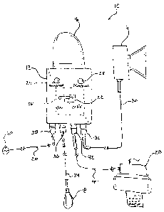
regulatory bodies
if the spill exceeds a certain volume of fluid. Accordingly, several
procedures
haven been attempted to prevent a spill. One procedure includes positioning a
member of the drilling crew, often termed a "watch man" to observe the
operation
of the trash pump and warn the driller if failure occurs, thus allowing the
driller to
attempt to stop drilling operations in a sufficient amount of time to prevent
an
overflow condition. Placing a watch man is not desirable because it removes a
man from the drilling crew that otherwise could be tending to more critical
1
, CA 02786246 2012-08-16
drilling operations. With the cost of drilling exceeding many thousands of
dollars
per hour, the loss of time due to the crew being a man short for the purpose
of
observing the trash pump can add up to substantial costs over the term of the
well.
[4] Another measure to prevent fluid spill includes utilizing a second trash
pump in
the cellar with the thought if one pump fails the other will still operate
sufficiently
to empty the cellar of collected fluid. However, this method tends to result
in one
or both of the pumps starving for fluid to pump, which is also used to cool
the
pump, resulting in premature pump failure from excessive heat.
[5] Yet another measure includes running a pipe in the ground to connect the
well
cellar to the separate tanks such that the fluid can flow under the force of
gravity
from the cellar to the tanks. However, this method is undesirable due to the
considerable costs associated with the installation of the conductor pipe.
[6] Accordingly, there is a need for an improved method and apparatus to
observe the
fluid level within the well cellar and to alert an operator to the existence
of an
undesirably high fluid level that indicates trash pump failure.
SUMMARY OF THE INVENTION
[7] Embodiments of the present invention meets the needs presented above by
providing a well cellar high fluid level alarm that operates to continually
sense the
fluid level within the well cellar and upon sensing a high fluid level
condition
2
, , CA 02786246 2012-08-16
operates visual and audible alarms to alert an operator of the high fluid
level
condition.
[8] Embodiments of the present invention also provide a well cellar high
fluid level
alarm that is operable in cold weather environments and in ice conditions.
[9] Embodiments of the present invention further provide a well cellar high
fluid
level alarm that is durable.
[10] Embodiments of the present invention further provide a well cellar high
fluid
level alarm that is operable in hazardous environments and includes a float
switch
having an operation that is not impeded by frozen fluid located in the well
cellar
or if the float itself becomes ice encrusted.
[11] Embodiment of the present invention further provide a well cellar high
fluid level
alarm that includes an emergency fluid pump disposed within the well cellar to
pump fluid therefrom in the instance of trash pump failure.
[12] To achieve these and other advantages, in general, in one aspect, a well
cellar
high fluid level alarm for use in connection with a well cellar during well
drilling
operations is provided. The alarm includes a control box providing a water-
tight
enclosure and a alarm control circuitry disposed within the control box. An
audible alarm indicator is operably connected to the alarm control circuitry.
A
3
, CA 02786246 2012-08-16
visual alarm indicator is operably connected to the alarm control circuitry. A
float
switch is operably connected to the alarm control circuitry. An electrical
power
cable is operably connected to the control circuitry and provides electrical
power
thereto. A control switch is operably connected to the control circuitry and
is
operable to turn the control circuitry on and off Operational indicator lamps
are
operably connected the control circuitry and operates to indicate an on or off
state
of the control circuitry. The control circuitry operates to operate the
audible
alarm indicator and the visual alarm indicator upon the float switch sensing a
high
fluid level.
[13] In general, in another aspect, the well cellar high fluid level alarm
includes a fluid
pump operably connected to the control circuitry and the control circuitry
further
operating to operate the fluid pump when a high fluid level is sensed by the
float
switch.
[14] In general, in another aspect, the well cellar high fluid level alarm
includes a
control box mounted to a support of a derrick and provides a water-tight
enclosure. Alarm control circuitry is disposed within the control box. An
audible
alarm indicator is mounted to a support of the derrick separate from the
control
box and in a position approximate to an operator. The audible alarm indicator
is
operably connected to the control circuitry. A visual alarm indicator is
supported
by the control box and is operably connected to the control circuitry. A float
switch suspended above and within the well cellar and is operably connected to
4
CA 02786246 2012-08-16
the alarm control circuitry. An electrical power cable is operably connected
to the
control circuitry and providing electrical power thereto. A control switch is
operably connected to the control circuitry and is operable to turn the
control
circuitry on and off An operational indicator lamp is operably connected the
control circuitry and operates to indicate an on state of the control
circuitry. A
fluid pump is disposed within the well cellar and is operable to pump fluid
within
the well cellar to a position exteriorly of the well cellar. The fluid pump is
operably connected to the control circuitry. The control circuitry operating
to
operate the audible alarm indicator, the visual alarm indicator and the fluid
pump
upon the float switch sensing a high fluid level within the well cellar.
[15] There has thus been outlined, rather broadly, the more important features
of the
invention in order that the detailed description thereof that follows may be
better
understood and in order that the present contribution to the art may be better
appreciated.
[16] Figure 1 is a schematic front view of a well cellar high fluid level
alarm
constructed in accordance with the principles of an embodiment of the
invention;
[17] Figure 2 is a block diagram of control circuitry and components of a well
cellar
high fluid level alarm in accordance with the principles of an embodiment of
the
invention;
5
CA 02786246 2012-08-16
[18] Figure 3 is a schematic environmental view of a well cellar high fluid
level alarm
in accordance with the principles of an embodiment of the invention;
[19] Figure 4 is a schematic view of a float switch of an embodiment of the
invention,
showing the float switch disposed within a well cellar having a low fluid
level
condition;
[20] Figure 5 is a schematic view of a float switch of an embodiment of the
invention,
showing the float switch disposed within a well cellar having a high fluid
level
condition; and
[21] Figure 6 is a schematic view of a well cellar high fluid level alarm
constructed in
accordance with the principles of an embodiment of the invention.
DETAILED DESCRIPTION OF THE INVENTION
[22] Referring now to FIGS. 1 through 5 of the drawings, there is
representatively
illustrated a well cellar high fluid level alarm 10 embodying the principals
and
concepts of an embodiment of the invention.
[23] The well cellar high fluid level alarm 10 comprises a housing or control
box 12,
an audible alarm indicator 14, such as a speaker or the like, a visual alarm
indicator 16, such as a strobe-light or the like, a float switch 18, an
electrical
6
% CA 02786246 2012-08-16
power cable 20, one or more control switches 22, an operational indicator
lamps
24 and 25, control circuitry 26, and optionally a fluid pump 28.
[24] Control box 12 is constructed of a sturdy material, such as, but not
limited to
stainless steel or the like, and further has a sealed construction providing a
water-
tight enclosure which serves to house and protect control circuitry 26 from
the
hazardous environment in which the alarm 10 is intended for use. In an
embodiment, it is contemplated the control box will be 10-inches wide, 12-
inches
high and 5-inches deep. While not illustrated here, the control box 12 may be
fitted with any number of suitable mount assemblies permitting attachment of
the
control box to various structural supports located within the in-use
environment as
desired by an operator.
[25] The audible alarm indicator 14 may be a speaker, such as a loud speaker
or the
like that is constructed for use in hazardous environments or any other
suitable
audio emitting device, such as, but not limited to piezoelectric devices. As
illustrated here, the audible alarm indicator 14 is separate from the control
box 12
so as to permit mounting thereof to a support structure as desired. However,
it is
contemplated the audible alarm indicator 14 may be attached to and supported
by
the control box 12. In the depicted configuration, the audible alarm indicator
14
includes a connector cable 30 that operably connects the audible alarm
indicator
to the control circuitry 26. Connector cable 30 may be fitted with an
electrical
connector 32 to permit decoupling of the connector cable 30. Electrical
connector
7
CA 02786246 2012-08-16
32 may be an explosion-proof type connector that is suitable for use in
hazardous
environments.
[26] The visual alarm indicator 16 may be a strobe-light of any suitable
construction
for use in a hazardous environment or other light emitting device for
attracting
attention. In the depicted embodiment, the visual alarm indicator 16 is
attached to
and supported by the control box 12. However, in other embodiments, the visual
alarm indicator 16 may be separate from the control box permitting mounting of
the visual alarm indicator to a support structure as desired. In this
embodiment,
the visual alarm indicator 16 would be fitted with a connector cable similar
to the
connector cable 30 of the audible alarm indicator 14. In either embodiment,
the
visual alarm indicator 16 is operably connected to the control circuitry 26.
[27] Float switch 18 comprises an electrical switch (not illustrated)
contained within a
bulb-shaped, water-tight housing and is constructed for heavy duty and
hazardous
environment use. Such a type of float switch is readily known in the technical
field. The float switch 18 is operably connected to the control circuitry 26
by
connector cable 34. Connector cable 34 may be fitted with an electrical
connector
36 to permit decoupling of the connector cable 34. Electrical connector 36 may
be an explosion-proof type connector that is suitable for use in hazardous
environments.
8
4 CA 02786246 2012-08-16
[28] Power cable 20 is operatively connected to the control circuitry 26 to
provide
electrical power to the control circuitry and to provide electrical power to
operate
the electric components of the alarm 10, such as the audible alarm indicator
14,
the visual alarm indicator 16 and the optional a fluid pump 28, etc. Power
cable
20 may be hardwired to a source of line-power 40 or may be fitted with a
suitable
electrical connector permitting the power cable to be plugged into an
electrical
power outlet. Power cable 20 may also be fitted with an electrical connector
36 to
permit decoupling of the connector cable 34. Electrical connector 36 may be an
explosion-proof type connector that is suitable for use in hazardous
environments.
[29] Control switch 22 is supported by the control box 12 and is operatively
connected
to the control electronics 26 and operable by an operator to turn the alarm 10
on
and off as desired by the operator. Operational indictor lamps 24 and 25 are
also
operatively connected to the control electronics 26 and are operated to
illuminate
when the alarm 10 is in the on or enabled (lamp 24) and when the alarm in off
or
disabled (lamp 25).
[30] Alarm 10 may further include a fluid pump 28 that is configured to be
positioned
within the cellar of the well and operated by the alarm to pump fluid from the
cellar when the alarm senses an undesired high fluid level within the cellar,
as
will be further discussed below. Pump 28 is operatively connected to the
control
electronics 26 a control or power cable 40 to receive electrical power and/or
control signals from the alarm 10 to operate the pump. In embodiments, the
pump
28 may be externally powered and receives control signals from the alarm 10 to
9
CA 02786246 2012-08-16
control the operation of the pump. Power cable or control cable 40 may also be
fitted with an electrical connector 42 to permit decoupling of the cable from
the
alarm 10. Electrical connector 42 may be an explosion-proof type connector
that
is suitable for use in hazardous environments.
[31] The control box 12 is mounted to a support, such as, but not limited to a
railing 44
of the drill derrick 46 in close proximity to the operator (not shown) of the
derrick. In the embodiment depicted, the audible alarm indicator 14 is mounted
to
a support beam 48 of the derrick 46 and in close proximity to the control box
12
such that the operator is capable of hearing the sound emitted from the
audible
alarm indicator in an alarm state. In an alternative embodiment (not shown),
the
visual alarm indicator 14 may not be supported by the control box 12, and
similar
to the audible alarm indicator 14 would also be mounted to a support beam of
the
derrick 46 in a position that is most likely visible to the operator.
Additionally,
float switch 18 is positioned within the cellar 50 and is suspended from above
by
attaching the connector cable 34 to a suitable location on the derrick 46. The
suspension height of the float switch 18 is adjusted to correspond to a high
fluid
level within the cellar 50.
[32] In use, it can now be understood, during drilling operations, drilling
fluid 52 also
referred to as drilling mud fills the cellar 50 and is pumped from the cellar
to mud
holding tanks (not shown) by a trash pump 54 where the drilling mud is then
recirculated for drilling. The drilling mud 52 contains, among other things,
rock
10
4 CA 02786246 2012-08-16
cuttings and other debris that is lifted to the surface by the flow of the
drilling
mud during drilling. The rock cuttings and other debris contained by the
drilling
mud often clog or damage the trash pump 54. In this circumstance, drilling mud
52 quickly fills and overflows the cellar 50, which is undesirable as
discussed
above.
[33] In an instance of a trash pump 54 failure, the alarm 10 operates the
audible
indicator 14 and the visual indicator 16 to alert the drill operator of a high
fluid
level in the cellar 50 as sensed by the float switch 18. In which instance,
the
operator can take an immediate reactive response to stop drill operations to
prevent the overflowing of the cellar 50. In embodiments of the alarm 10
wherein
pump 28 is installed and positioned within the cellar 50, the alarm 10 will
further
operate the pump 28 to pump drilling mud 52 from the cellar to the mud tanks
to
provide the operator with a response time to shut down the drilling operations
to
prevent further filling of the cellar.
[34] Referring now to FIG. 6 there is illustrated an additional embodiment of
the alarm
in accordance with the invention. Here, alarm 10 further includes a mounting
plate 60 to which the control box 12, the audible alarm 14 and the visual
alarm 16
are attached. The mounting plate 60 is then attached to support of a derrick.
11