Note: Descriptions are shown in the official language in which they were submitted.
CA 02786596 2014-11-28
METHOD AND APPARATUS FOR ASSISTED/COORDINATED INTRA-HOME
COMMUNICATIONS
BACKGROUND
[0002] The telecommunication landscape, within a typical home or office, may
encompass a number of independently developed radio access technologies and
standards.
These technologies were initially designed for target applications and they
perform
relatively well for these applications.
SUMMARY
[0003] Systems, methods, and instrumentalities are disclosed that may provide
assistance across networks using different radio access technologies. A
centralized
gateway (COW) may be provided to facilitate the assistance via client devices
in the
networks. The COW and client devices may use a common protocol and common
interface to take actions relatinL, to the assistance.
[0004] The COW may collect information from a first client device over a first
radio access technology using a common protocol. The COW may fuse the
information
collected from the first client device with information associated with a
second client
device. For example, the information collected from the first client device
may be
combined with other information received from the second device, other
devices, other
networks, etc. The COW may determine, based on the fused information, an
action to be
performed by the first client device over a second radio access technology to
provide the
assistance. The assistance may be a control function and/or an assistance
service. The
COW may send an instruction, using the common protocol, to the first client
device to
perform the action. For example, the first client device may be
- 1 -
CA 02786596 2012-07-06
WO 2011/085073
PCT/US2011/020331
associated with a first network configured to operate using a first radio
access technology; and,
the second client device may be associated with a second network configured to
operate using a
second radio access technology. The instruction may direct the first client
device to activate the
second radio access technology and communicate with the second client device
over the second
radio access technology to provide the assistance.
100051 A client device may provide information to the CGW over a first radio
access
technology using a common protocol. For example, the client device may be
associated with a
network configured to operate using the first radio access technology. In
addition, the client
device may attach to the CGW and provide one or more of: the radio access
technolog(ies)
supported by the client device, operating mode information, location
information,
services/capability information, etc. The client device may receive an
instruction from the CGW
to perform an action over a second radio access technology to provide
assistance across
networks. The instruction may be received over the first radio access
technology using the
common protocol. The client device may perform the action over the second
radio access
technology. For example, the client device may provide assistance to another
network
configured to operate using the second radio access technology.
BRIEF DESCRIPTION OF THE DRAWINGS
100061 A more detailed understanding may be had from the following
description,
given by way of example in conjunction with the accompanying drawings wherein:
100071 Figure 1 illustrates a typical home network environment;
100081 Figure 2 illustrates an exemplary CGW in communication with capillary
networks and external networks;
100091 Figure 3 illustrates an exemplary centralized gateway connected to a
plurality of
capillary networks and external networks;
100101 Figure 4 illustrates an exemplary attachment procedure;
100111 Figure 5 illustrates an exemplary coordination of a direct link setup;
100121 Figure 6 illustrates an exemplary frequency band change;
100131 Figure 7 illustrates an exemplary system operation diagram;
100141 Figure 8 illustrates an exemplary client protocol stack;
100151 Figure 9 illustrates an exemplary mapping of network assistance;
100161 Figure 10 illustrates an exemplary wireless communication system;
100171 Figure 11 provides a further detailed view of the exemplary wireless
communication system of Figure 10;
- 2 -
CA 02786596 2012-07-06
WO 2011/085073
PCT/US2011/020331
100181 Figure 12A is a system diagram of an example communications system in
which
one or more disclosed embodiments may be implemented;
100191 Figure 12B is a system diagram of an example wireless transmit/receive
unit
(WTRU) that may be used within the communications system illustrated in Figure
12A; and
100201 Figure 12C is a system diagram of an example radio access network and
an
example core network that may be used within the communications system
illustrated in Figure
12A.
DETAILED DESCRIPTION OF ILLUSTRATIVE EMBODIMENTS
100211 Figures 1-12 may relate to exemplary embodiments in which the disclosed
systems, methods and instrumentalities may be implemented. However, while the
present
invention may be described in connection with exemplary embodiments, it is not
limited thereto
and it is to be understood that other embodiments may be used or modifications
and additions
may be made to the described embodiments for performing the same function of
the present
invention without deviating therefrom.
100221 Figure 1 illustrates a typical home network environment 100 with a
sampling of
these technologies. Access to content (e.g., web and video) may be provided
via a broadband
modem through the home owner's intern& protocol (IP) backhaul connection(s)
(e.g., digital
subscriber line (DSL), cable, fiber to the home (FTTH), satellite, etc.).
Mobile services (e.g.,
voice and data) are provided through the cellular network, e.g., either via a
macro cell (where
coverage permits), or via a femtocell. The femtocell may use the homeowner's
IP backhaul to
connect to the cellular network.
100231 Wireless Local Area Network (WLAN) Access Points (APs) may provide data
connectivity between PCs, laptops, and other networked devices (e.g., printers
and faxes) using
WIFI technology. Bluetooth links may be used for point- to-point technology
(e.g., between
cameras and PCs, between keyboards/mice and PCs, between mobile phones and
wireless
headsets). High throughput point-to-point links may be used. A typical use
case for such high-
speed links is for video distribution cable replacement (e.g., Set Top Box
(STB) to high
definition television (HDTV)). Wireless sensor networks, e.g., for monitoring
of heating,
ventilating and air conditioning (HVAC) systems, lighting systems, may be
used.
100241 Table 1 lists some features of each of radio access technologies. Table
1 is a
high level comparison of the specific technologies in terms of four major
criteria (range, peak
throughput, channel bandwidth, and operating band). The channel bandwidth in
Table 1 denotes
- 3 -
CA 02786596 2012-07-06
WO 2011/085073
PCT/US2011/020331
the spectrum occupied by a typical transmission. The specific details for each
of the technologies
may be found in the relevant applicable standards.
TABLE 1
Technology Relevant Typical Throughput Device Network Channel
Operational
Standards Range (Peak Requirements Formation/ Bandwidth Frequency
bands
(most Data Rates) Device
typical) Discovery
WIFI IEEE < 100 m 802.11a ¨ 54 Portability & Manual 22 MHz
Unlicensed bands:
802.11 Mbps mobility selection of
802.11a ¨ 5 GHz
Family 802.11b ¨11 expected frequency
channel in 802.11b/g ¨ 2.4
Mbps
band. GHz
802.11g- 54
Mbps Access Point 802.11n-2.4 & 5
broadcast GHz
802.11n¨ 600 periodic
Mbps beacon
frames
to allow
device
ZigBee Maintained 70-300m 2.4 GHz band Low cost, Initial 2 MHz
Unlicensed bands:
by the ¨250 kbps low power Channel
868 MHz in
ZigBee consumption, scan by
915 MHz band- Europe,
Alliance, short range coordinator
40 915 MHz in the
Based on device
kbit/s Mobility USA
IEEE
not Device and Australia, and
802.15.4 868 MHz band
expected discovery by 2.4 GHz worldwide
MAC and
Beacon
PHY 20 kbit/s search
or probe
request/resp
nse
Bluetooth Maintained < 10m V1.2 - 1 Mbps Low power Initial
1 MHz Unlicensed bands:
by V2.0EDR - 3 consumption, pairing
Bluetooth Mbps short range, requires 3.0 HS 2.4
GHz band
SIG 3.0 HS -24 Mobility not some requires a
Mbps Expected manual bandwidth of
intervention. 22 MHz
Procedure
can
be long.
- 4 -
CA 02786596 2012-07-06
WO 2011/085073
PCT/US2011/020331
Wireless Maintaine < 10 m As high as 25 High power Initial 1.76 GHz
Unlicensed bands:
HD d Gbps allowed Channel
by the scan by 60 GHz band
Wireless coordinator (large
HD device available spectrum
consortiu
Probe 7 GHz)
request/resp
onse
mechanism
for
device
discovery
Cellular 3GPP "Cellular R8 WCDMA-42 Mobility WCDMA:5 Licensed bands
WCDMA " Mbps DL & 11 permitted MHz each
Mbps for e.g. Cellular, PCS
LTE UL UL and DL (1900 MHz), IMT
(2100 MHz), 700
R8 LTE - 150 LTE: 1.4 - MHz,..
Mbps 20
DL & 73Mbps MHz each
UL for
UL and DL
Ethernet Wired Technology (likely based on
IEEE 802.3)
100251 The following observations may be made about in-home technologies,
including: 1) the range of a device may depend greatly on the specific
technology; 2) some
technologies using unlicensed spectrum operate in the 2.4 GHz band; 3) higher
data throughputs
may rely on the use of the 5GHz band and the 60 GHz band (the latter may be
useful for the
transmission of video traffic); 4) some technologies may require manual
intervention prior to
network formation (e.g., channel selection for WIFI networks); and 5) for most
technologies,
device discovery may be allowed either through periodic beacons or
probe/request mechanisms.
100261 A number of interferers may exist in a typical home including: cordless
phones
(which may have 5- 10 MHz bandwidth), baby monitors, microwave ovens (some
older devices
emit a dirty signal over the entire 2.4 GHz band), wireless video cameras,
game controllers and
fluorescent lights, to name a few. Each of the technologies in a home or
office may be a closed
network. There may be no coordination between the network technologies. They
may rely on
their own procedures for network formation, network discovery, service
discovery, and
interference management. This may result in inefficiencies.
100271 A "wireless transmit/receive unit (WTRU)" may include any electronic
device
that is capable of transmitting and/or receiving data via one or more wireless
interfaces. The term
WTRU may include but is not limited to a user equipment (UE), a mobile
station, a fixed or
mobile subscriber unit, a pager, a cellular telephone, a personal digital
assistant (PDA), a
- 5 -
CA 02786596 2012-07-06
WO 2011/085073
PCT/US2011/020331
computer, or any other type of device capable of operating in a wireless
environment. A "MTC
WTRU" or a "M2M WTRU" is a WTRU capable of communicating using MTC/M2M
technology. When referred to hereafter, the terminology "base station" may
include but is not
limited to a Node-B, a site controller, an access point (AP), or any other
type of interfacing
device capable of operating in a wireless environment. When referred to
hereafter, the term
"network node" may include a logical or physical entity that implements
functionality in a core
network or radio access network (RAN), such as but not limited to a base
station, gateway,
access server, or any other entity.
100281 Various home/office network technologies may be referred to as
capillary
networks. Assistance may be provided to a capillary network, which may improve
performance
within the capillary network. A centralized gateway (CGW) is disclosed that
may facilitate such
assistance, e.g., via client devices in capillary networks. The CGW may be
referred to as a
converged gateway, centralized entity, central entity etc. A client device may
be referred to as a
client.
100291 Figure 2 illustrates an exemplary CGW 210, which may be in
communication
with capillary networks 220 and external networks 230. CGW 210 may provide
access to
external networks 230 (e.g., cellular, Internet, etc.). CGW 210 may
communicate with capillary
networks 220 over a common interface, such as the logical "A" interface 215
that provides
signaling support for a set of control procedures that are managed by a
"common logical A
protocol." CGW 210 may collect information from capillary networks 220 and/or
external
networks230 and fuse the information. CGW 210 may use the fused information in
providing
assistance to capillary networks 220 and their devices. The assistance may
include, or may be
referred to, as one or more of the following without limitation: assistance,
assistant service(s),
network control, coordination, routing, measurements, service, etc. The
assistance may include
controlling one capillary network to assist another capillary network.
100301 At least one device in a capillary network may be capable of
communicating
over the logical A interface. A CGW may provide assistance to capillary
networks through, for
example: 1) coordination of spectrum usage (interference management); 2) node
discovery
assistance; 3) inter capillary network communication; 4) intra capillary
network communication;
5) assisted service discovery (e.g., broadcast of ongoing sessions for peer
gaming); 6) assisted
load management; 7) set-up of opportunistic assistance through mobile devices;
8) assisted
location mapping, etc.
100311 Assistant services refer to services that may rely on fused and/or raw
data stored
in the centralized gateway (CGW) to assist and coordinate capillary networks.
Assistant services
- 6 -
CA 02786596 2012-07-06
WO 2011/085073
PCT/US2011/020331
may reside in both the CGW and in attached devices. Assistant services may
rely on common
logical A protocol procedures for communication between the CGW and attached
devices.
100321 A CGW may provide assistance and coordination among different capillary
networks based on fused and raw information from the capillary networks and
the external
networks. The CGW may run a common logical A protocol and communicate with
client devices
within the capillary networks using a logical A interface. Furthermore, the
CGW may run the
assistant services that make use of the fused and raw data.
100331 Capillary networks (CNs) may refer to networks managed either directly
or
indirectly by the CGW. Capillary networks may include ZigBee networks, WIFI
networks,
Bluetooth networks, direct links, infrastructure networks, etc. An attached
device (AD) may refer
to a device that has attached or made its presence known to the CGW. An AD may
be
synchronized with the CGW, and may receive transmitted control information. An
AD may
provide a capability indication to the CGW.
100341 A physical location may refer to a location of a device in physical
space (e.g., X,
Y, Z coordinates, a room, etc.). A radio location may refer to a location of
the device with
respect to the ability to communicate, e.g., with the CGW. A coverage zone may
refer to the
cover of the CGW. The coverage zone may apply in an office environment, a
commercial
environment, etc.
100351 Figure 3 illustrates an exemplary centralized gateway, CGW 310,
connected to a
plurality of capillary networks (capillary network A 320, capillary network B
322 and capillary
network C 324) and external networks 330. Information may be collected from
the capillary
networks and external networks 330 and fused in CGW 310. CGW 310 may use the
fused
information to 1) provide assistance services and network control to one of
the capillary
networks to which the central entity is connected (e.g., radio frequency (RF)
measurements and
characteristics, such as location information from capillary network A 320,
may be collected and
fused in the central entity to assist capillary network B 322); 2) control one
of the capillary
networks in assisting another capillary network (e.g., location and device
capability of capillary
network A 320 and capillary network B 322 may be collected and fused in the
central entity
where the CGW may control a device in capillary network A 320 to assist
capillary network B
322), etc.
100361 Information collection from the capillary networks, as well as
signaling to carry
control or assistance information to the plurality of capillary networks, may
be enabled by a
common logical interface, which may be referred to as the logical A interface
or common logical
A interface. This interface may link the common logical A protocol, which may
reside in CGW
- 7 -
CA 02786596 2012-07-06
WO 2011/085073
PCT/US2011/020331
310 and the client devices in the capillary networks. In CGW 310, the common
logical A
protocol may be a common upper layer 311 to multiple radio access technologies
(RATs) (X, Y,
and Z) and may allow communication with a plurality of capillary networks. The
logical A
interface may require modification of the MAC and PHY layer of the RATs that
support the
logical A interface.
100371 A CGW may provide assistance and coordination to capillary networks, as
well
as the capability for inter-capillary network routing. A CGW may provide
communications to
external networks (e.g., cellular, Internet, etc.) through, for example, a
wireless cellular interface,
a residential IP connection (e.g., through DSL, cable, FTTH), a satellite
connection, etc. A CGW
may be an evolved Wireless LAN access point, an evolved H(e)NB, a converged
device which
has both functionalities (and possibly other functionalities), etc. Mobile
phones may behave as
CGWs, e.g., where they have the multi RAT capability.
100381 It may be necessary for each device in the capillary networks to
communicate
through a physical link with the CGW. Devices that do communicate with the
CGW, may
associate with the CGW and may be referred to as attached devices (ADs).
Communication may
be through the logical A interface, that may provide synchronization, control,
a data plane
functionality, etc. The control information may provide signaling between
capillary network
devices and the CGW to enable CGW managed assistance and coordination.
100391 These functions may be achieved through dedicated channels, that may be
a
separate channel for each AD, or through shared channels, for instance using
carrier sense
multiple access/collision avoidance (CSMA/CA). Synchronization may provide the
capillary
network devices with reference timing, an indication of where to find the
control information,
etc. The control information may provide signaling between a capillary network
device and the
CGW, to enable CGW managed assistance and coordination.
100401 The logical A interface may be implemented using an air interface,
which may
be optimized for the specific application and conditions (e.g., home, office,
industrial, etc.). It
may also be implemented by a logical A protocol, which may be a common layer
sitting on top
of multiple existing RATs. The logical A interface may be based on any other
technology. For
instance, if the CGW has H(e)NB functionality and WIFI, the logical A protocol
may reside on
top of the Uu interface (evolved H(e)NB interface) and a 802.11 interface.
100411 ADs may possess at least one RAT that may be capable of communicating
with
the CGW. They may possess a common logical A protocol, which may sit on top of
supported
RATs, that manages logical A interface procedures. Client versions of
assistant services may
also be present in the ADs.
- 8 -
CA 02786596 2012-07-06
WO 2011/085073
PCT/US2011/020331
100421 The CGW and the client device may use a common protocol, such as the
logical
A protocol, to collect and format information from capillary networks over
multiple RATs. This
may enable standard based collection across multiple RATs. For example,
measurements
collected over RAT X for a given client, using an existing standard based
approach, may be
transmitted over a format common to each RATs. The common logical A protocol
may allow
decisions based on fused data from multiple capillary networks to be sent to
clients of a specific
RAT and may enable new procedures for multi-RAT clients.
100431 When a device wants to join the network and communicate with the CGW to
take advantage of the services it offers and is capable of multiple RAT
operation, the use of the
common logical A protocol may enable the device to attach to the CGW and to
inform it of its
multi-RAT capability, and other capabilities, using any available RAT
technology.
100441 Figure 4 illustrates an exemplary attachment procedure. At 1, client
420 may
discover the network (CGW 410) by acquiring the synchronization and control
information
broadcast by the network using a given RAT technology (e.g., RAT Y). Client
420 may use any
of the RAT technologies which it can support, in this case RAT X, RAT Y and
RAT Z. At 2,
client 420 may attach with CGW 410 using RAT Y. For example, client 420 may
use RAT Y to
attach with the network to get a network address, a MAC address, etc. At 3,
client 420 may use
the recently activated RAT Y to send an attachment request through the common
logical A
protocol. The attachment request may include the multi-RAT capabilities of
client 420. This may
enable CGW 410 to trigger the activation of another RAT at 4, or at some later
time. The
attachment procedure may include capability information that is pertinent for
multi-RAT service
assistance.
100451 The attachment request may include one or more of the following: a)
each RAT
supported by client 420; b) for each RAT, what bands are supported; c) for
each RAT, what
other RAT it may support simultaneously (e.g., a GSM RAT may support Bluetooth
but may not
support WCDMA or LTE); d) for each RAT, whether the RAT is active or not; e)
location
tracking capability; or f) TVWS capability, whether the device is a Mode 1,
Mode II, or Sensing
only device. The attachment request may include information relating to
services offered by
client 420 (e.g., gaming, printing, storage and physical location, etc.).
100461 At 4, CGW 410 may send an attachment response, which may indicate if
the
attachment request is accepted. This procedure may be complemented with
authentication and
security procedures. The attachment response may include a command to activate
another RAT
as an alternative or supplemental RAT based on the capability provided in the
attachment
- 9 -
CA 02786596 2012-07-06
WO 2011/085073
PCT/US2011/020331
request. This command may include the same information carried in a secondary
RAT activation
request.
100471 The common logical A protocol at the CGW, such as CGW 410, may maintain
a
state machine for each client to maintain knowledge of which RAT, with its
operating band, is
active at a given time. The common logical A protocol at the client device,
such as client 420,
may maintain a state machine for the network in order to maintain knowledge of
which RAT is
active at a given time in its surroundings.
100481 The logical A protocol in a CGW may broadcast the available RAT and
associated bands supported by the network. This information may be signaled
through any
available RAT, e.g., in a periodic fashion. This may enable clients to
activate another RAT
autonomously without having to discover the other RATs available.
100491 The activation of a secondary RAT of a given device already operating
on a
primary RAT may be initiated by the device itself or by the CGW. A device may
initiate the
activation triggered by a user decision or based on a device application
decision (e.g., on a cell
phone operating on a cellular network, a user enables a Bluetooth RAT to
transfer files to a PC).
The CGW may initiate and instruct network devices to activate a secondary RAT
in a context of
network assistance. For instance, the CGW may instruct a device to enable a
secondary RAT to
perform sensing in order to assist another network operating primarily on the
secondary RAT.
The CGW may instruct two devices to enable a secondary RAT in order to setup a
direct link
between these two devices on that RAT (e.g., the CGW coordinates 802.11n/TVWS
direct link
setup between a TV and a Setup-Box attached primarily to the CGW on a
802.11/ISM band).
100501 Whether it is a device or a CGW initiated activation, the common
logical A
protocol may define procedures to support the secondary RAT activation. These
procedures may
include a device sending a secondary RAT activation indication signal to the
CGW which may
include one or more of the following: 1) a nature of the indication (e.g., the
device informing the
CGW of the device's decision, the device requesting assistance from the CGW to
provide a
designation of the RAT and/or the RAT configuration, etc.); 2) a RAT to
Activate; or 3) a RAT
configuration which may include the used band, channel information, power
setting, antenna
setting, etc. If the nature of the indication is to request assistance, the
CGW may send back a
secondary RAT activation response with the requested information. A secondary
RAT
deactivation indication and response may be transmitted at the termination of
the RAT operation.
100511 The common logical A protocol may define a procedure to support the
secondary RAT activation which may include the CGW sending a secondary RAT
activation
request signal to a device, or a set of devices. Before sending this request,
the common logical A
- 10 -
CA 02786596 2012-07-06
WO 2011/085073
PCT/US2011/020331
protocol at the CGW may verify capabilities of the devices and whether the RAT
is already
active or not, e.g., by using the state machine for each device. The request
may include one or
more of the following: 1) an activation cause, such as sensing, direct link
setup, location
tracking; 2) a RAT to activate; 3) a RAT configuration which may include the
used band,
channel information, power setting, antenna setting (e.g., when activating a
Bluetooth RAT, the
device may be told the channel hopping sequence.) This feature may be used to
speed up
capillary network discovery.; 4) a time to activate; 5) a device role (e.g.,
the CGW may request a
device to play a role of an AP or a client when enabling a WI-FT RAT); 6) peer
devices
identification which may be applicable when direct link setup or device
location tracking is used;
or 7) in case of an activation for sensing, the CGW may provide measurement
configuration
information (e.g., which events to monitor, when to send back measurement
reports (periodic or
triggered), etc.).
100521 The devices may accept or may reject the activation request and may
send a
secondary RAT activation confirmation. When the request is rejected, a reason
may be included.
A secondary RAT deactivation request and confirmation may be required to
terminate the RAT
operation. The common logical A protocol at the CGW may dynamically maintain
the state
machine for each client on the activation or deactivation of a RAT.
100531 Figure 5 illustrates an exemplary coordination of a direct link setup
between two
client devices. In Figure 5, CGW 510 may coordinate the setup of a direct link
on a secondary
RAT X between two devices, client A 520 and client B 530, that are already
attached to CGW
510 through different primary RATs, RAT Y and RAT Z, respectively.
100541 At A, CGW 510 may instruct client A 520 to activate RAT X and establish
communication with client 530. At B, CGW 510 may instruct client B 530 to
activate RAT X
and establish communication with client A 520. At C, client A 520 and client B
530 may activate
RAT X. At D, client A 520 may associate with client B 530 using RAT X.
100551 A number of procedures may be enabled by the common logical A protocol
that
may result in a change of the operating mode of an entire capillary network or
of a specific
capillary network device. The term "operating mode" may refer to one or more
of: 1) frequency
band of operation; 2) frequency channel of operation; 3) transmission related
parameters which
may include modulation, coding, power, and directivity; 4) capillary network
media access
configuration parameters; or 5) device client role (e.g., router, end device,
coordinator, etc.)
where, for example, a WIFI station may be asked to act as a access point for
load balancing or
range extension. The operating mode may be changed based on the fused data
available at CGW
-11 -
CA 02786596 2012-07-06
WO 2011/085073
PCT/US2011/020331
510 and assistant services logic. The decision is sent to target attached
devices, which are then
responsible for initiating the operating mode change.
100561 In Figure 6, an exemplary frequency band change is depicted. This is a
procedure whereby the CGW may use fused data to determine that a capillary
network may
change the operating frequency band. It may be understood that a similar
mechanism may be
used for the other procedures, which may include using different signaling.
100571 Referring to Figure 6, at 1, CGW 610 determines that it may need to
change the
frequency band for capillary network A 630 based on fused data information. A
decision
algorithm may rely on fused information related to one or more of device
location, capillary
network load, interference levels or spectrum availability (e.g., whitespace).
For example, an
assistance service in CGW 610 may determine that the interference level on the
current operating
frequency is high, and that a change of band may be needed to maintain a
suitable quality of
service for capillary network A 630. In another example, an assistant service
in CGW 610 may
determine that the current band is experiencing congestion and may request a
band change for
load balancing reasons.
100581 At 2, CGW 610 may send a control message to an attached client device
(Client
A 620) within capillary network A 630, requesting a change of operating band.
The message
may include one or more of the following: 1) new operating band and frequency;
2) device
transmission related parameters (e.g., modulation, coding, Tx power, etc.); 3)
time-related
parameters (e.g., when the change is to take effect, if this is a synchronous
change, maximum
time to complete change, etc.); 4) result of a failure case (e.g., what to do
if the capillary network
is not capable of performing the band change, for instance, the capillary
network may be directed
to stop operation or to continue on the current band using different
transmission parameters); or
5) type of result to return for a success.
100591 At 3, client A 620 may initiate a capillary network protocol over RAT X
to
effect the change of the operating band. For example, if the capillary network
is a 802.15.4
ZigBee WPAN network, the attached device, client A 620, may communicate with
the WPAN
Network Manager to request a change of channel. If the operation is
successful, at 4, capillary
network A 630 may change the operating band. At 5, client A 620 may respond
with an
indication of a successful operating mode change. Otherwise, the client A may
respond with an
indication of a failed operating mode change.
100601 The logical A protocol may include one or more of the procedures
described in
Table 2. Secondary RAT activation and operating mode change may use one or
more of the
procedures described in Table 2.
- 12 -
CA 02786596 2012-07-06
WO 2011/085073
PCT/US2011/020331
Table 2
A interface Initialization Procedure to initialize the A interface channel,
which may potentially include a
synchronization channel, a control-plane channel, and a user-plane channel
This
initialization details the mechanism to transport the A interface
synchronization, control,
and user-plane data, over the underlying RAT technologies.
A interface Procedure to allow CGW to reconfigure the A interface (for
instance changing the mapping
Reconfiguration of the synchronization, control, and user-plane data from
RAT X to RAT Y).
A interface Failure Procedure to recover from an A-interface failure, as
measured at the Logical A protocol.
Upon detection of an A-interface failure, the Attached Devices can to continue
communicating within their capillary networks. Failure can be determined by
monitoring a
combination of the signal quality of a synchronization channel and the
received cyclic
redundancy Check (CRC) failures over an observation window, and declaring a
failure if
the quality of the signal or number of CRC errors passes a threshold [8][9].
Set of procedures that allow use of the A-interface link to route traffic
between two
Attached devices within a capillary network or across two capillary networks.
In one embodiment the Common Logical A protocols in the two Attached Devices
would
set up routing entries in the capillary network devices so that data would be
siphoned out
over the A interface and then siphoned back into the capillary network. At the
CGW, the
Common Logical A protocol would set up the
transparent link between the two attached devices. This would be especially
useful in
capillary networks that form tree topologies which have a large depth (e.g
ZigBee
networks). When devices at opposite ends of this tree need to communicate, the
large depth
translates into multi-hop transmission and significant routing delays. The CGW
can act as a
relay, linking outlying devices of a capillary network and reducing the number
of
transmission hops.
Routing In a second embodiment, the routing procedures are used to
allow recovery from a direct
link failure. The A interface is used as a temporary bridge between the direct
link devices
until a new link is established.
Device Paging Procedure used by a CGW to wake up a "sleeping" device that
is not continuously
monitoring the A interface. In one embodiment, the CGW sends a paging request
for Client
A through a Client B. CGW sends the paging request to Client B (an Attached
Device not
in sleep mode), which then forwards the paging request, through the capillary
network, to
Client A.
Device Neighbour Procedure to establish a location map of attached devices
(allows CGW to determine which
Discovery devices are in communication range). In one embodiment, the
procedure is initiated by the
CGW, which tells the Common Logical A protocol in the Attached Devices to send
out
probe signals within the capillary network. The probe responses are used to
build a
neighbour map for each of the Attached Devices. This Neighbour map can be
forwarded to the CGW to be used by a fusion algorithm.
Procedure used by CGW to broadcast information to Attached Devices (or devices
wanting
Management of to Attach). The content of the broadcast information can be
provided by one or more
Broadcast Assistant Services based on fused data (for example the
service data described in Section
information Error! Reference source not found.)
Proxy Device Attachment Procedure used by an Attached Device to inform the CGW
of a legacy device that cannot
communicate over the A interface. The Common Logical A Protocol in the
Attached
Device can provide information that would be contained in the normal
Attachment
procedure, For example, RAT capability, service capability, device location,
etc
- 13 -
CA 02786596 2012-07-06
WO 2011/085073
PCT/US2011/020331
Capillary Network Procedure whereby a CGW performs translation to allow
inter-capillary network
Translation communication.
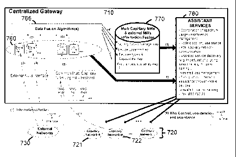
100611 Figure 7 illustrates an exemplary system operation diagram. CGW 710 may
collect, through the logical A-interface, information (e.g., RF measurements,
network operation
measurements, traffic rate, load, devices location, devices capabilities,
etc.) from the capillary
networks 720 as well as from the external networks 730. This information may
be collected
during device attachment to the CGW. This information may be collected during
ongoing device
operation, for instance upon a change or periodically. For CGW 710 to collect
information,
CGW 710 may control and configure devices of capillary networks 720 to report
the
information. CGW 710 may create specific databases 760 per network (e.g.,
capillary network
and external network) from the collected information. CGW 710 may execute a
set of data fusion
algorithms 765. A data fusion algorithm may fuse information collected from
capillary networks
720 and/or external networks 730. CGW 710 may be dynamically updated and
configured with
information fusion algorithms. Exemplary information fusion database 770 may
include, but is
not limited to, one or more of device location map, services/capability
repository, capillary
networks coverage map, or frequencies availability map.
100621 CGW 710 may collect and fuse device location information into a devices
location map, e.g., from one or more capillary networks. The fused information
may be a map of
multi-network attached device locations, which may be a physical location or a
radio location.
The fused information may be used by CGW 710 to provide one or more of
assistant services,
such as assistant services 780, which may include any of the assistance
disclosed herein. For
example, assistant services 780 may include one or more of: emergency location
services within
the home or office, device maintenance (e.g., to know the location of a mobile
device that has
malfunctioned), coordination of spectrum usage, node discovery assistance,
inter-capillary
network communication, assisted service discovery, assisted load management,
set-up of
opportunistic assistance through mobile devices, assisted location mapping,
etc. This fused data
may assist with spectrum management. CGW 710 may base spectrum management
decisions on
the density of attached devices, thereby avoiding assigning spectrum which may
be heavily used
in certain locations.
100631 CGW 710 may collect from capillary networks 720 capability information
and
service information of devices and it may fuse this into a creating a
Services/Capability
Repository. The capability information may include radio access capabilities
(e.g., supported
technologies, radio bands, receive and transmit bit rates, transmit power
limits, etc.) as well as
- 14 -
CA 02786596 2012-07-06
WO 2011/085073
PCT/US2011/020331
information dealing with other physical attributes such as power source (e.g.,
battery and mains),
available power (e.g., for battery operated devices), storage capability,
available storage, etc. The
service information may include an indication of the ongoing services or
potential services that
may be offered by the devices in the capillary networks. The use of a proxy
device attachment
procedure may allow CGW 710 to keep track of service/capability information
for devices that
do not directly communicate with CGW 710 (e.g., they have no A interface). The
proxy devices
may relay the service/capability information to CGW 710. This information may
be fused with
other types of fused information including the devices location map.
100641 The fused information may be stored in the information fusion database
770.
Information fusion database 770 may be dynamically and periodically updated,
e.g., by data
fusion algorithms 765 execution. New types of information fusion may be added
in the
information fusion database.
100651 CGW 710 may enclose a set of assistant services 780 to control,
coordinate and
assist capillary networks 720. Assistant services 780 may make use of fused
information as well
as the collected raw information specific to the individual networks, such as
the information
available at specific databases 760. A variety of assistant services may be
defined. CGW 710
may be dynamically updated and configured with new assistant services. CGW 710
may control
and assist by controlling directly one capillary network. CGW 710 may control
one of the
capillary networks in assisting and controlling another capillary network.
100661 The system architecture enables a variety of assistant services 780.
Each
assistant service may make use of the information fusion database 770 and
individual capillary
networks databases in order to assist directly a capillary network and/or to
control one of the
capillary networks in assisting another capillary network. CGW 710 may request
capillary
network A 721, or specific devices belonging to capillary network A 721, to
sense the operating
channel with a specific sensing algorithm applicable to capillary network B
722, in order to assist
capillary network B 722. In a context of low power low complexity devices like
ZigBee/802.15.4
capillary networks, devices may spend most of their time in a sleep mode to
save power and may
have limited sensing capability. These types of networks may not perform
active RF-
measurements. They may be subject to dynamic interference. In that context, a
co-located
capillary network like the WI-Fl Network, capillary network A 721, may take
sensing
measurements to assist a ZigBee network.
100671 CGW 710 may collect device location information and operating
characteristics
of a ZigBee network as well as a WIFI Network, which may include the operating
channel of the
ZigBee network. CGW 710 may then instruct Wi-Fi devices to perform periodic RF-
- 15 -
CA 02786596 2012-07-06
WO 2011/085073
PCT/US2011/020331
measurements on the ZigBee's operating channel with a specific sensing
algorithm applicable to
ZigBee networks. These RF-Measurements may be collected periodically at CGW
710. CGW
710 may periodically fuse the RF-Measurements per WIFI device with the WIFI
devices location
map as well as the ZigBee devices location map in order to detect high
interference occurring on
the ZigBee channel. Consideration of RF-measurements may be limited to WIFI
devices
collocated with the ZigBee devices. Once the interference is detected, CGW 710
may inform the
ZigBee network and/or control the ZigBee network by instructing the ZigBee
ADs, devices
attached to CGW 710 through the logical A interface, to initiate a network
channel switch.
100681 CGW 710 may instruct the WIFI devices to monitor a valid alternate
channel for
the ZigBee network. Once high interference is detected, CGW 710 may control
the ZigBee
network to switch channels to the validated alternate channel. Service
discontinuity that may
occur as a result of the interference, may be reduced at the ZigBee network.
100691 CGW 710 may setup and control a proxy device with multi-RAT capability
by
providing opportunistic network healing assistance to a given capillary
network. As CGW 710
communicates with ADs from multiple technologies, it may ask the devices to
help in the
operation of one or more capillary networks. The assistance may be
opportunistic in that there
may be no guarantee that any AD is in range of the target capillary network.
The final decision
of whether to assist may be left to the AD. For instance, an AD may decide to
refrain from
providing opportunistic assistance to conserve battery power.
100701 Still referring to Figure 7, at 1, CGW 710 may collect information
about
capillary networks 720 and external networks 730, e.g., in terms of their
connectivity, their
location, their RAT capabilities, etc. Information is gathered and fused as
illustrated at 2, 3 and
4. CGW 710 may run an application at 5 to determine a needed assistant
services 780, e.g., detect
or confirm that a device in a given capillary network (e.g., capillary network
A 721) is not
connected to the capillary network, which may be referred to as a singleton
device or node. The
singleton detection application may also be triggered by some of the devices
in the capillary
network informing CGW 710. At 6, CGW 710 may provide assistance to capillary
networks 720.
100711 A network healing assistance application may be triggered by CGW 710.
Using
information fusion database 770, CGW 710 may identify a device with multi-RAT
capability
(e.g., a device with RAT capability Y assuming capillary network A 721 uses
RAT Y) in the
vicinity of the projected location of the singleton node. This device may be
referred to as a proxy
healing device. Since this device may not have the RAT used by capillary
network A active,
CGW 710 may inform the proxy healing device of its needs, possibly using the
device's current
active RAT (e.g., RAT X). This may trigger the activation of RAT Y, which is
used by the
- 16 -
CA 02786596 2012-07-06
WO 2011/085073
PCT/US2011/020331
singleton node. The proxy healing device may communicate with the singleton
node or possibly
neighbor nodes to reconnect the singleton node with its neighbors. For
example, capillary
network A 721 may be based on Bluetooth technology (e.g., Bluetooth may equate
to RAT Y).
In a scatternet, Bluetooth nodes may be master or slave nodes. A master node
may not connect
with another master node, therefore creating a bottleneck in the capillary
network. The proxy
healing device may interact with these nodes and force them to change their
role thus repairing
the node permanently.
100721 A proxy healing device may broadcast information to speed up network
formation and network joining by communicating to legacy ZigBee networks that
cannot attach
to CGW 710. In such a case, the mobile acts as a relay for control messages
to/from the capillary
network.
100731 Network healing assistance may be provided by gathering information
about a
capillary network and signaling this information to CGW 710. The information
may be
"filtered" at the healing device and indications sent to CGW 710 based on the
filtered data and on
certain thresholds. The AD and the capillary network need not be limited to
the cases described.
100741 As an example, the attached device may be a smartphone that has
attached with the
CGW and provided, in its capability information, an indication that it
supports ZigBee. The CGW
may then request that the attached device provide assistance to the ZigBee
network. This assistance
may include one or more of: 1) extending the reach of the CGW by transmitting
sync/control channel
information as a proxy for the CGW; 2) connecting to the ZigBee capillary
network and acting as a
temporary router within the capillary network, or a gateway to the CGW.
100751 Proxy tracking services may be provided. One or more devices currently
inactive in capillary network A 721 may be used to track the location of a
device with an
unknown location or with no location tracking capability belonging to
capillary network A 721.
A request to track a device with unknown location may be handled by CGW 710 by
first
identifying one or more devices with known location or tracking location
capability and with
RAT capability compatible with the device with the unknown location. The
identified devices
may activate the compatible RAT and may start scanning around to actively or
passively detect
the presence of the device with the unknown location. If a device finds the
device with the
unknown location, it may inform CGW 710 and provide additional observation
characteristics
such as signal strength. For example, there may be a request to find a
Bluetooth enabled camera.
smartphones spread around the house or other consumer electronics devices with
a known
location may be requested to activate Bluetooth radio and scan for the camera
using Bluetooth
technology.
- 17 -
CA 02786596 2012-07-06
WO 2011/085073
PCT/US2011/020331
100761 Capillary networks services discovery assistance may be provided. Using
fused
information, including information relating to available/ongoing services on a
plurality of RATs
of the capillary networksõ CGW 710 may assist a device (or devices) from a
capillary network
to enable a specific RAT and use a service. This may be useful in order to
share peer-to-peer
applications (e.g., gaming). For example, upon entering a home or after
turning on a smartphone,
the device may attach to CGW 710 through the common logical A interface (e.g.,
WIFI). Upon
attaching, the smartphone may inform CGW 710 about its service preferences and
its
capabilities. CGW 710 may fuse and use the service/capabilities repository
with the devices
location map in the information fusion database 770 and issue a directed
response to the
smartphone with service offerings in its vicinity, based on the device's
preferences/capabilities.
The smartphone may be made aware of the service offerings through broadcast
information by
CGW 710. After a user selects an ongoing service, like a game, CGW 710 may
assist the
smartphone with the location where the game is taking place and provide a
direction and/or a
distance. CGW 710 may provide a location map on the physical home layout.
While the user is
moving to the location (e.g., a room in the house) where the game is taking
place on a Bluetooth
network, CGW 710 may assist the smartphone in enabling its Bluetooth RAT,
which by default
may be disabled, and configure it with the channels to use and the channel
hopping sequence.
Therefore, the smartphone may have a fast association to the Bluetooth network
which may offer
a fast game start experience to the user.
100771 A capillary network optimization assistance service may be a service
whereby a
CGW may use its fused and raw data to help optimize the performance of a
capillary network
(e.g., by maximizing throughput, minimizing delay, etc.). For example, many
capillary networks
may use a form of carrier sensing as part of the medium access protocol (e.g.,
CSMA/CA). If a
centralized entity, such as a CGW, is present, it may be used to assist in the
Media Access
Control (MAC) algorithm in a number of ways, which may include one or more of:
1) providing
a frame/slot structure to allow slotted CSMA; 2) broadcasting a jamming signal
to signal to an
attached device that a collision has occurred, which may eliminate the need
for request-to-send
and clear-to-send (RTS/CTS) transmissions; 3) signaling/broadcasting dynamic
MAC parameters
(e.g., in 802.11, this may include the inter-frame spacing parameters, the
random backoff
parameters after sensing a busy channel) where the CGW may use its knowledge
of the AD
location and service profile to tailor parameters in order to maximize
throughput or minimize
interference; or 4) augmenting the basic CSMA/CA algorithm by reserving a
portion of the
spectrum resources to a demand assigned based access control where the CGW may
manage
- 18 -
CA 02786596 2012-07-06
WO 2011/085073
PCT/US2011/020331
capacity requests from ADs, and assign capacity based on any number of
metrics, including but
not limited to fairness and traffic priority.
100781 In addition, an assistant service may provide load management within
capillary
networks. For example, a CGW may decide to rearrange a capillary network. The
CGW may
decide to split a capillary network into two, or more, smaller capillary
networks and provide
inter-capillary network communication between such networks. The throughput on
each of the
split networks may then be independently maximized. This may require that the
CGW be made
aware of the load in a capillary network (e.g., routing congestion, delay
statistics, throughput
statistics, etc.). The CGW may instruct specific devices to change their
parent router to another
more lightly loaded router.
100791 An interference management assistance service may use fused information
relating to measured interference, device location, and device capability to
request devices to use
directed antennas, thereby pointing energy to the desired recipient and away
from other devices
that may be sharing the same band. The assistant service may provide the
necessary information
to the devices (e.g., location, transmit power, etc.) through broadcast
information carried over the
common logical A interface. The common logical A protocol in these devices may
interpret the
broadcast information and autonomously determine the direction of
transmission.
100801 The interference management assistant service may provide for time
sharing of
a frequency channel. The CGW may coordinate a time sharing of a frequency
channel across K
capillary networks. The CGW may provide a usage schedule for the K capillary
networks, and
the common logical A protocol in the attached devices may control capillary
network
transmissions based on this schedule.
100811 The interference management assistant service may assist in
spectrum/interference management. The interference management assistant
service may talk to a
centralized spectrum manager entity (reachable through the cellular network
and/or Internet) that
may reserve or assign a spectrum across multiple bands for intra-home use that
is of "high
quality" (e.g., low interference). The spectrum manager may allocate a
spectrum dynamically
based on requests from the CGW. It may make the allocation and re-allocation
decisions based
on other metrics, received measurement information from other CGWs, white
space use, etc.
100821 Once a spectrum is assigned to the CGW, the CGW may be responsible for
managing the spectrum within the home. For instance, it may choose to assign
frequency
channels to individual capillary networks based on received requests. The size
and frequency
band of the assignment may be a function of the traffic to be carried on the
capillary network.
- 19 -
CA 02786596 2012-07-06
WO 2011/085073
PCT/US2011/020331
100831 The CGW may use device location information and/or the physical layout
of the
coverage zone to request devices to use directed antennas, thereby, pointing
energy to the desired
recipient and away from other devices that may be sharing the same band. The
CGW may
provide the necessary information to the devices (e.g., location, transmit
power, etc.) and have
the devices autonomously determine the direction of transmission.
100841 The CGW may also control interference by limiting the transmit power of
the
devices in the capillary networks. The CGW may set the initial transmit power
of ADs based on
an open loop technique, and then change this limit dynamically as interference
conditions
change. The CGW may limit the minimum transmit power of an AD, for instance,
to guarantee
coverage within the capillary network.
100851 A session transfer assistance service may use fused data to enable a
CGW to
control a session transfer between devices. For instance, a video session may
be transferred from
a smartphone to a HDTV. The session transfer assistance service may make use
of the location
map, capability map, and fused load/interference information to select the
device to which to
transfer a session (e.g., target device). The CGW may be responsible for
paging the target device,
setting up the intra-home path from the broadband modem (or other such device
that receives the
content) and the target device, reformatting the data to meet the service
display requirements of
the target device and tearing down the link to the smartphone.
100861 Figure 8 illustrates an example client protocol stack in a client
device 820. In
order to support CGW network assistance concepts, client devices may require
two types of
entities. First, a client logical A protocol 830 may be needed to implement
different procedures
of the logical A interface, which may include one or more of a) device
attachment to the CGW
and providing services/capabilities of devices which may allow filling-up the
services/capabilities repository in the information fusion database; b)
measurement configuration
and reporting; c) RAT activation/deactivation, where, for example, the CGW may
activate the
Bluetooth RAT of the smartphone to join an ongoing game in a Bluetooth
network; or d) channel
configuration/reconfiguration as may be used in the inter-capillary network
sensing assistance
service to switch a channel of a network experiencing high interference or as
may be used in the
capillary networks services discovery assistance service where the activated
Bluetooth RAT is
configured with the channels information. Second, one or more client assistant
applications 840
may interact with CGW services in order to enable CGW assistance. Client
device 820 may be
dynamically updated and configured with new client assistant applications 840.
An example of a
client assistant application is illustrated in the capillary networks services
discovery assistance
service. When a CGW informs a device of available games, the user may select a
game through a
- 20 -
CA 02786596 2012-07-06
WO 2011/085073
PCT/US2011/020331
client assistant application with a user interface. The client assistant
application with a user
interface may display to the user the location map of the location where the
game is taking place.
100871 Figure 9 shows an exemplary mapping 900 of the assistance/coordination
functions and procedures described herein, within a machine-to-machine (M2M)
type capillary
network 920. CGW 910 may perform centralized gateway functions as described
herein.
100881 Figure 10 shows an example wireless communication system 1000, which
may be
configurable to perform the methods and features described above with
reference to Figures 1-9. The
wireless communication system 1000 includes an Evolved-Universal Terrestrial
Radio Access
Network (E-UTRAN) 1005. The E-UTRAN 1005 may be connected to a System
Architecture
Evolution (SAE) core network (not depicted). The E-UTRAN 1005 includes a WTRU
1010 and
several evolved Node-Bs, (eNBs) 1020, which may be H(e)NBs and/or macro
NodeBs. The WTRU
1010 is in communication with an eNB 1020. The eNBs 1020 interface with each
other using an X2
interface. Each of the eNBs 1020 interface with a Mobility Management Entity
(MME)/Serving
GateWay (S-GW) 1030 through an 51 interface. Although a single WTRU 1010 and
three eNBs 1020
are shown in Figure 10, it should be apparent that any combination of wireless
and wired devices may
be included in the wireless communication system
1000.
100891 Figure 11 is an example block diagram of an LTE wireless communication
system
1100 including the WTRU 1110, the eNB 1020, and the MME/S-GW 1030. As shown in
Figure 11,
the WTRU 1110, the eNB 1020 and the MME/S-GW 1030 which may be configured to
perform the
methods and features described above with reference to Figures 1-9.
100901 In addition to the components that may be found in a typical WTRU, the
WTRU
1110includes a processor 1116 with an optional linked memory 1122, at least
one transceiver 1114, an
optional battery 1120, and an antenna 1118. The processor 1116 may configured
to generate, encode,
decode, and process messages as described above with reference to Figures 1-9.
The transceiver 1114
is in communication with the processor 1116 and the antenna 1118 to facilitate
the transmission and
reception of wireless communications. The transceiver 1114 may be configured
to generate, transmit,
and receive messages such as those described above with reference to Figures 1-
9. In case a battery
1120 is used in the WTRU 1110, it may power the transceiver 1114 and the
processor 1116.
100911 In addition to the components that may be found in a typical eNB, the
eNB 1020
includes a processor 1117 with an optional linked memory 1115, transceivers
1119, and antennas
1121. The processor 1117 may be configured to perform the methods and features
described above
with reference to Figures 1-9. The transceivers 1119 are in communication with
the processor 1117
and antennas 1121 to facilitate the transmission and reception of wireless
communications. The
- 21 -
CA 02786596 2012-07-06
WO 2011/085073
PCT/US2011/020331
transceivers 1119 may be configured to generate, transmit, and receive
messages such as those
described above with reference to Figures 1-9. The eNB 1020 is connected to
the Mobility
Management Entity/Serving GateWay (MME/S-GW) 1030 which includes a processor
1133 with an
optional linked memory 1134.
100921 Although not shown in Figure 10, one or more MTC servers may be
connected to the
communication system 1000 of Figure 10. Although Figures 10-11 describe an LTE-
based system,
LTE is described purely by way of example, and the principles described above
with reference to
Figures 1-9 may also be applicable to architectures that include microcell,
picocell, femtocell, and/or
macrocell base stations, core networks, and/or WTRUs based on technologies
such as WiMax,
Wireless Broadband (WiBro), Global System for Mobile Communications (GSM),
Enhanced Data
Rates for GSM Evolution (EDGE) Radio Access Network (GERAN), Institute of
Electrical and
Electronics Engineers (IEEE) 802.11x, Institute of Electrical and Electronics
Engineers (IEEE)
802.15, WLAN, UMTS/UMTS Terrestrial Radio Access Network (UTRAN), LTE-Advanced
(LTE-
A), Code Division Multiple Access-2000 (CDMA2000), or any other technology
that supports M2M
communication.
100931 Figure 12A is a diagram of an example communications system 1200 in
which one
or more disclosed embodiments may be implemented. The communications system
1200 may be a
multiple access system that provides content, such as voice, data, video,
messaging, broadcast, etc., to
multiple wireless users. The communications system 1200 may enable multiple
wireless users to
access such content through the sharing of system resources, including
wireless bandwidth. For
example, the communications systems 1200 may employ one or more channel access
methods, such
as code division multiple access (CDMA), time division multiple access (TDMA),
frequency division
multiple access (FDMA), orthogonal FDMA (OFDMA), single-carrier FDMA (SC-
FDMA), and the
like.
100941 As shown in FIG. 12A, the communications system 1200 may include
wireless
transmit/receive units (WTRUs) 1202a, 1202b, 1202c, 1202d, a radio access
network (RAN) 1204, a
core network 1206, a public switched telephone network (PSTN) 1208, the
Internet 1210, and other
networks 1212, though it will be appreciated that the disclosed embodiments
contemplate any number
of WTRUs, base stations, networks, and/or network elements. Each of the WTRUs
1202a, 1202b,
1202c, 1202d may be any type of device configured to operate and/or
communicate in a wireless
environment. By way of example, the WTRUs 1202a, 1202b, 1202c, 1202d may be
configured to
transmit and/or receive wireless signals and may include user equipment (UE),
a mobile station, a
fixed or mobile subscriber unit, a pager, a cellular telephone, a personal
digital assistant (PDA), a
smartphone, a laptop, a netbook, a personal computer, a wireless sensor,
consumer electronics, and the
- 22 -
CA 02786596 2012-07-06
WO 2011/085073
PCT/US2011/020331
like.
100951 The communications systems 1200 may also include a base station 1214a
and a base
station 1214b. Each of the base stations 1214a, 1214b may be any type of
device configured to
wirelessly interface with at least one of the WTRUs 1202a, 1202b, 1202c, 1202d
to facilitate access to
one or more communication networks, such as the core network 1206, the
Internet 1210, and/or the
networks 1212. By way of example, the base stations 1214a, 1214b may be a base
transceiver station
(BTS), a Node-B, an eNode B, a Home Node B, a Home eNode B, a site controller,
an access point
(AP), a wireless router, and the like. While the base stations 1214a, 1214b
are each depicted as a
single element, it will be appreciated that the base stations 1214a, 1214b may
include any number of
interconnected base stations and/or network elements.
100961 The base station 1214a may be part of the RAN 1204, which may also
include other
base stations and/or network elements (not shown), such as a base station
controller (B SC), a radio
network controller (RNC), relay nodes, etc. The base station 1214a and/or the
base station 1214b may
be configured to transmit and/or receive wireless signals within a particular
geographic region, which
may be referred to as a cell (not shown). The cell may further be divided into
cell sectors. For
example, the cell associated with the base station 1214a may be divided into
three sectors. Thus, in
one embodiment, the base station 1214a may include three transceivers, i.e.,
one for each sector of the
cell. In another embodiment, the base station 1214a may employ multiple-input
multiple output
(MIMO) technology and, therefore, may utilize multiple transceivers for each
sector of the cell.
100971 The base stations 1214a, 1214b may communicate with one or more of the
WTRUs
1202a, 1202b, 1202c, 1202d over an air interface 1216, which may be any
suitable wireless
communication link (e.g., radio frequency (RF), microwave, infrared (IR),
ultraviolet (UV), visible
light, etc.). The air interface 1216 may be established using any suitable
radio access technology
(RAT).
100981 More specifically, as noted above, the communications system 1200 may
be a
multiple access system and may employ one or more channel access schemes, such
as CDMA,
TDMA, FDMA, OFDMA, SC-FDMA, and the like. For example, the base station 1214a
in the RAN
1204 and the WTRUs I202a, 1202b, 1202c may implement a radio technology such
as Universal
Mobile Telecommunications System (UMTS) Terrestrial Radio Access (UTRA), which
may establish
the air interface 1216 using wideband CDMA (WCDMA). WCDMA may include
communication
protocols such as High-Speed Packet Access (HSPA) and/or Evolved HSPA (HSPA+).
HSPA may
include High-Speed Downlink Packet Access (HSDPA) and/or High-Speed Uplink
Packet Access
(HSUPA).
100991 In another embodiment, the base station 1214a and the WTRUs 1202a,
1202b, 1202c
- 23 -
CA 02786596 2012-07-06
WO 2011/085073
PCT/US2011/020331
may implement a radio technology such as Evolved UMTS Terrestrial Radio Access
(E-UTRA),
which may establish the air interface 1216 using Long Term Evolution (LTE)
and/or LTE-Advanced
(LTE-A). [0149] In other embodiments, the base station 1214a and the WTRUs
1202a, 1202b, 1202c
may implement radio technologies such as IEEE 802.16 (i.e., Worldwide
Interoperability for
Microwave Access (WiMAX)), CDMA2000, CDMA2000 lx, CDMA2000 EV-DO, Interim
Standard 2000 (IS-2000), Interim Standard 95 (IS-95), Interim Standard 856 (IS-
856), Global System
for Mobile communications (GSM), Enhanced Data rates for GSM Evolution (EDGE),
GSM EDGE
(GERAN), and the like.
101001 The base station 1214b in FIG. 12A may be a wireless router, Home Node
B, Home
eNode B, or access point, for example, and may utilize any suitable RAT for
facilitating wireless
connectivity in a localized area, such as a place of business, a home, a
vehicle, a campus, and the like.
In one embodiment, the base station 1214b and the WTRUs 1202c, 1202d may
implement a radio
technology such as IEEE 802.11 to establish a wireless local area network
(WLAN). In another
embodiment, the base station 1214b and the WTRUs 1202c, 1202d may implement a
radio
technology such as IEEE 802.15 to establish a wireless personal area network
(WPAN). In yet another
embodiment, the base station 1214b and the WTRUs 1202c, 1202d may utilize a
cellular-based RAT
(e.g., WCDMA, CDMA2000, GSM, LTE, LTE-A, etc.) to establish a picocell or
femtocell. As shown
in FIG. 12A, the base station 1214b may have a direct connection to the
Internet 1210. Thus, the base
station 1214b may not be required to access the Internet 1210 via the core
network 1206.
101011 The RAN 1204 may be in communication with the core network 1206, which
may
be any type of network configured to provide voice, data, applications, and/or
voice over internet
protocol (VoIP) services to one or more of the WTRUs 1202a, 1202b, 1202c,
1202d. For example, the
core network 1206 may provide call control, billing services, mobile location-
based services, pre-paid
calling, Internet connectivity, video distribution, etc., and/or perform high-
level security functions,
such as user authentication. Although not shown in FIG. 12A, it will be
appreciated that the RAN
1204 and/or the core network 1206 may be in direct or indirect communication
with other RANs that
employ the same RAT as the RAN 1204 or a different RAT. For example, in
addition to being
connected to the RAN 1204, which may be utilizing an EUTRA radio technology,
the core network
1206 may also be in communication with another RAN (not shown) employing a GSM
radio
technology.
101021 The core network 1206 may also serve as a gateway for the WTRUs 1202a,
1202b,
1202c, 1202d to access the PSTN 1208, the Internet 1210, and/or other networks
1212. The PSTN
1208 may include circuit-switched telephone networks that provide plain old
telephone service
(POTS). The Internet 1210 may include a global system of interconnected
computer networks and
- 24 -
CA 02786596 2012-07-06
WO 2011/085073
PCT/US2011/020331
devices that use common communication protocols, such as the transmission
control protocol (TCP),
user datagram protocol (UDP) and the interne protocol (IP) in the TCP/IP
internet protocol suite. The
networks 1212 may include wired or wireless communications networks owned
and/or operated by
other service providers. For example, the networks 1212 may include another
core network connected
to one or more RANs, which may employ the same RAT as the RAN 1204 or a
different RAT.
101031 Some or all of the WTRUs 1202a, 1202b, 1202c, 1202d in the
communications
system 1200 may include multi-mode capabilities, i.e., the WTRUs 1202a, 1202b,
1202c, 1202d may
include multiple transceivers for communicating with different wireless
networks over different
wireless links. For example, the WTRU 1202c shown in FIG. 12A may be
configured to
communicate with the base station 1214a, which may employ a cellular-based
radio technology, and
with the base station 1214b, which may employ an IEEE 802 radio technology.
101041 FIG. 12B is a system diagram of an example WTRU 1202. As shown in FIG.
12B,
the WTRU 1202 may include a processor 1218, a transceiver 1220, a
transmit/receive element 1222, a
speaker/microphone 1224, a keypad 1226, a display/touchpad 1228, non-removable
memory 1206,
removable memory 1232, a power source 1234, a global positioning system (GPS)
chipset 1236, and
other peripherals 1238. It will be appreciated that the WTRU 1202 may include
any sub-combination
of the foregoing elements while remaining consistent with an embodiment.
[0155] The processor
1218 may be a general purpose processor, a special purpose processor, a
conventional processor, a
digital signal processor (DSP), a plurality of microprocessors, one or more
microprocessors in
association with a DSP core, a controller, a microcontroller, Application
Specific Integrated Circuits
(ASICs), Field Programmable Gate Array (FPGAs) circuits, any other type of
integrated circuit (IC), a
state machine, and the like. The processor 1218 may perform signal coding,
data processing, power
control, input/output processing, and/or any other functionality that enables
the WTRU 1202 to
operate in a wireless environment. The processor 1218 may be coupled to the
transceiver 1220, which
may be coupled to the transmit/receive element 1222. While FIG. 12B depicts
the processor 1218 and
the transceiver 1220 as separate components, it will be appreciated that the
processor 1218 and the
transceiver 1220 may be integrated together in an electronic package or chip.
101051 The transmit/receive element 1222 may be configured to transmit signals
to, or
receive signals from, a base station (e.g., the base station 1214a) over the
air interface 1216. For
example, in one embodiment, the transmit/receive element 1222 may be an
antenna configured to
transmit and/or receive RF signals. In another embodiment, the
transmit/receive element 1222 may be
an emitter/detector configured to transmit and/or receive IR, UV, or visible
light signals, for example.
In yet another embodiment, the transmit/receive element 1222 may be configured
to transmit and
receive both RF and light signals. It will be appreciated that the
transmit/receive element 1222 may be
- 25 -
CA 02786596 2012-07-06
WO 2011/085073
PCT/US2011/020331
configured to transmit and/or receive any combination of wireless signals.
101061 In addition, although the transmit/receive element 1222 is depicted in
FIG. 12B as a
single element, the WTRU 1202 may include any number of transmit/receive
elements 1222. More
specifically, the WTRU 1202 may employ MIMO technology. Thus, in one
embodiment, the WTRU
1202 may include two or more transmit/receive elements 1222 (e.g., multiple
antennas) for
transmitting and receiving wireless signals over the air interface 1216.
101071 The transceiver 1220 may be configured to modulate the signals that are
to be
transmitted by the transmit/receive element 1222 and to demodulate the signals
that are received by
the transmit/receive element 1222. As noted above, the WTRU 1202 may have
multi-mode
capabilities. Thus, the transceiver 1220 may include multiple transceivers for
enabling the WTRU
1202 to communicate via multiple RATs, such as UTRA and IEEE 802.11, for
example.
101081 The processor 1218 of the WTRU 1202 may be coupled to, and may receive
user
input data from, the speaker/microphone 1224, the keypad 1226, and/or the
display/touchpad 1228
(e.g., a liquid crystal display (LCD) display unit or organic light- emitting
diode (OLED) display unit).
The processor 1218 may also output user data to the speaker/microphone 1224,
the keypad 1226,
and/or the display/touchpad 1228. In addition, the processor 1218 may access
information from, and
store data in, any type of suitable memory, such as the non-removable memory
1206 and/or the
removable memory 1232. The non-removable memory 1206 may include random-access
memory
(RAM), read-only memory (ROM), a hard disk, or any other type of memory
storage device. The
removable memory 1232 may include a subscriber identity module (SIM) card, a
memory stick, a
secure digital (SD) memory card, and the like. In other embodiments, the
processor 1218 may access
information from, and store data in, memory that is not physically located on
the WTRU 1202, such
as on a server or a home computer (not shown).
101091 The processor 1218 may receive power from the power source 1234, and
may be
configured to distribute and/or control the power to the other components in
the WTRU 1202. The
power source 1234 may be any suitable device for powering the WTRU 1202. For
example, the
power source 1234 may include one or more dry cell batteries (e.g., nickel-
cadmium (NiCd), nickel-
zinc (NiZn), nickel metal hydride (NiMH), lithium-ion (Li-ion), etc.), solar
cells, fuel cells, and the
like.
[OHO] The processor 1218 may also be coupled to the GPS chipset 1236, which
may be
configured to provide location information (e.g., longitude and latitude)
regarding the current location
of the WTRU 1202. In addition to, or in lieu of, the information from the GPS
chipset 1236, the
WTRU 1202 may receive location information over the air interface 1216 from a
base station (e.g.,
base stations 1214a, 1214b) and/or determine its location based on the timing
of the signals being
- 26 -
CA 02786596 2012-07-06
WO 2011/085073
PCT/US2011/020331
received from two or more nearby base stations. It will be appreciated that
the WTRU 1202 may
acquire location information by way of any suitable location-determination
method while remaining
consistent with an embodiment.
101111 The processor 1218 may further be coupled to other peripherals 1238,
which may
include one or more software and/or hardware modules that provide additional
features, functionality
and/or wired or wireless connectivity. For example, the peripherals 1238 may
include an
accelerometer, an e-compass, a satellite transceiver, a digital camera (for
photographs or video), a
universal serial bus (USB) port, a vibration device, a television transceiver,
a hands free headset, a
Bluetootht module, a frequency modulated (FM) radio unit, a digital music
player, a media player, a
video game player module, an Internet browser, and the like.
101121 FIG. 12C is a system diagram of the RAN 1204 and the core network 1206
according to an embodiment. As noted above, the RAN 1204 may employ an EUTRA
radio
technology to communicate with the WTRUs 1202a, 1202b, 1202c over the air
interface 1216. The
RAN 1204 may also be in communication with the core network 1206.
101131 The RAN 1204 may include eNode-Bs 1240a, 1240b, 1240c, though it will
be
appreciated that the RAN 1204 may include any number of eNode-Bs while
remaining consistent with
an embodiment. The eNode-Bs 1240a, 1240b, 1240c may each include one or more
transceivers for
communicating with the WTRUs 1202a, 1202b, 1202c over the air interface 1216.
In one
embodiment, the eNode-Bs 1240a, 1240b, 1240c may implement MEMO technology.
Thus, the
eNode-B 1240a, for example, may use multiple antennas to transmit wireless
signals to, and receive
wireless signals from, the WTRU 1202a. [0165] Each of the eNode-Bs 1240a,
1240b, 1240c may be
associated with a particular cell (not shown) and may be configured to handle
radio resource
management decisions, handover decisions, scheduling of users in the uplink
and/or downlink, and the
like. As shown in FIG. 12C, the eNode-Bs 1240a, 1240b, 1240c may communicate
with one another
over an X2 interface.
101141 The core network 1206 shown in FIG. 12C may include a mobility
management
gateway (MME) 1242, a serving gateway 1244, and a packet data network (PDN)
gateway 1246.
While each of the foregoing elements are depicted as part of the core network
1206, it will be
appreciated that any one of these elements may be owned and/or operated by an
entity other than the
core network operator.
101151 The MME 1242 may be connected to each of the eNode-Bs 1242a, 1242b,
1242c in
the RAN 1204 via an Si interface and may serve as a control node. For example,
the MME 1242 may
be responsible for authenticating users of the WTRUs 1202a, 1202b, 1202c,
bearer
activation/deactivation, selecting a particular serving gateway during an
initial attach of the WTRUs
-27 -
CA 02786596 2012-07-06
WO 2011/085073
PCT/US2011/020331
1202a, 1202b, 1202c, and the like. The MME 1242 may also provide a control
plane function for
switching between the RAN 1204 and other RANs (not shown) that employ other
radio technologies,
such as GSM or WCDMA.
101161 The serving gateway 1244 may be connected to each of the eNode Bs
1240a, 1240b,
1240c in the RAN 1204 via the Si interface. The serving gateway 1244 may
generally route and
forward user data packets to/from the WTRUs 1202a, 1202b, 1202c. The serving
gateway 1244 may
also perform other functions, such as anchoring user planes during inter-eNode
B handovers,
triggering paging when downlink data is available for the WTRUs 1202a, 1202b,
1202c, managing
and storing contexts of the WTRUs 1202a, 1202b, 1202c, and the like.
101171 The serving gateway 1244 may also be connected to the PDN gateway 1246,
which
may provide the WTRUs 1202a, 1202b, 1202c with access to packet- switched
networks, such as the
Internet 1210, to facilitate communications between the WTRUs 1202a, 1202b,
1202c and IP-enabled
devices.
101181 The core network 1206 may facilitate communications with other
networks. For
example, the core network 1206 may provide the WTRUs 1202a, 1202b, 1202c with
access to circuit-
switched networks, such as the PSTN 1208, to facilitate communications between
the WTRUs 1202a,
1202b, 1202c and traditional land-line communications devices. For example,
the core network 1206
may include, or may communicate with, an IP gateway (e.g., an IP multimedia
subsystem (IMS)
server) that serves as an interface between the core network 1206 and the PSTN
1208. In addition, the
core network 1206 may provide the WTRUs 1202a, 1202b, 1202c with access to the
networks 1212,
which may include other wired or wireless networks that are owned and/or
operated by other service
providers.
101191 Although features and elements are described above in particular
combinations, one
of ordinary skill in the art will appreciate that each feature or element can
be used alone or in any
combination with the other features and elements. In addition, the methods
described herein may be
implemented in a computer program, software, or firmware incorporated in a
computer-readable
medium for execution by a computer or processor. Examples of computer-readable
media include
electronic signals (transmitted over wired or wireless connections) and
computer- readable storage
media. Examples of computer-readable storage media include, but are not
limited to, a read only
memory (ROM), a random access memory (RAM), a register, cache memory,
semiconductor
memory devices, magnetic media such as internal hard disks and removable
disks, magneto-optical
media, and optical media such as CD-ROM disks, and digital versatile disks
(DVDs). A processor in
association with software may be used to implement a radio frequency
transceiver for use in a WTRU,
UE, terminal, base station, RNC, or any host computer.
- 28 -
CA 02786596 2012-07-06
WO 2011/085073
PCT/US2011/020331
- 29 -