Note: Descriptions are shown in the official language in which they were submitted.
CA 02786768 2012-07-11
WO 2011/085825 PCT/EP2010/054993
1
Floor panel assembly and floor panel for use therein
The present invention relates to a floor panel
assembly comprising sheet-shaped floor panels, which floor
panels are provided with a plurality of edges, a lower side and
an upper side, whereby the floor panels are intended to be
joined by means of joining members, each floor panel being
provided on at least a first edge with a first joining member
and, on a second edge, with a second joining member, the first
and second joining members of two panels being adapted to be
joined by a movement of the two panels with their first and
second edges towards to each other such that in the joined
position the panels meet each other near their upper side along
a seam, the first and second joining members locking the panels
at the adjacent edges at least in a direction perpendicular to
the upper side and in a direction parallel to the upper side but
perpendicular to the adjacent first and second edges in their
joined position, the first and second joining members being
provided with at least one deformable locking element which is
deformable, during said joining, from a first position allowing
the first and second joining members to be joined, to a second
position in which it locks the first and second joining members
to each other at least in said direction parallel to the upper
side.
Floor panel assemblies having vertical joining members
are already known, for example from US 2009/0064624 Al.
According to the invention, the deformable locking
element is formed such that, in its second position, it locks
the first and second joining members to each other in both said
directions parallel and perpendicular to the upper side.
In one embodiment, the floor panel assembly is
provided on one of the first and second joining members and
comprises a first locking surface co-operating with a second
locking surface on the other of said first and second joining
members.
In a particular embodiment the second locking surface
on the other of the first and second joining members is inclined
CA 02786768 2012-07-11
WO 2011/085825 PCT/EP2010/054993
2
and is facing away from the seam in the joined position of the
panels. This enables a lock in both directions with one set of
locking surfaces only.
In a further development the locking element is
provided with at least one and particularly two hinges, and in
the joined position, one edge of the locking element being fixed
to one of the first and second joining members and the other
edge being provided with said first locking surface. The hinges
allow a predetermined deformation of the locking element, while
the formation of the locking surface at a free end of the
locking element allows the locking element to wrap around one of
said first and second joining members.
In an embodiment, the other end of the locking element
comprises a hook bearing said first locking surface, whereas the
other of the first and second joining members comprises a recess
including said second locking surface.
In another embodiment, the first locking surface of the
locking element extends substantially parallel to the direction
in which the first and second joining members are joined to each
other, when in its first position. This allows the other of said
first and second joining members to easily pass the locking
surface of the locking element before both locking surfaces
engage.
In a further embodiment, the locking element comprises
a control portion adapted to co-operate with a control portion
on the other of the first and second joining members in order to
control movement of the locking element from the first to the
second position. This allows for a precise control of the
deformation of the locking element and required movement of the
locking surface.
In a particular embodiment, the control portion of the
locking element is at a distance from an underlying portion of
the one of said first and second joining members in the first
position, whereas a portion between the locking surface and the
control portion is substantially adjacent to the underlying
portion of the one of said first and second joining members.
This configuration allows a deformation of the locking element
CA 02786768 2012-07-11
WO 2011/085825 PCT/EP2010/054993
3
in the direction of the underlying joining member which then
causes at least a rotation of the locking surface.
Conveniently, the first and second joining members are
configured as a male and female joining member, the locking
element being attached to the female joining member. This allows
the locking element to deform into the female joining member and
to thereby wrap around the male joining member holding it in one
or two directions.
In an embodiment, the female joining member comprises a
depression which is at least locally covered by the locking
element, the male joining member comprising a protrusion adapted
to co-operate with the locking element at a position above the
depression of the female joining member. The protrusion of the
male joining member could have a recess bearing the second
locking surface on its side remote from the seam and at a
distance from a crest of the protrusion.
In a further development, the locking element is
provided with at least one hinge which is positioned to co-
operate with a crest of the protrusion of the male joining
member. This allows the locking element to take the shape of the
male joining member.
It is however also conceivable that the deformable
locking element is attached to the male joining member, and has
a control portion that is activated by an upward protrusion of
the female member. The locking surface will then engage with a
locking surface of the female joining member.
In a particular embodiment, the first locking surface
on the locking element is at an angle of 90 or less relative to
the adjacent surface on the locking element. This allows for a
strong lock.
In a favourable embodiment, the locking element is
constructed such that it requires force to move the locking
element between the first and second positions and preferable
through an intermediate position where a pretension in the
locking element is reversed. This creates a distinct first and
second position for the locking element and also enables the
CA 02786768 2012-07-11
WO 2011/085825 PCT/EP2010/054993
4
locking element to securely lock the other joining member to
enable a proper connection between the panels.
Conveniently, the locking element is made of a separate
plastic part, and any hinges are film hinges. It would also be
conceivable to make the locking element from a metal.
In a particular embodiment, a plurality of locking
elements is provided along the respective edge. This leads to
narrower locking elements allowing easy connection of the
adjacent panel edges, also when the edges do not make a
perpendicular movement, for example if the panels are folded
down.
Conveniently, the locking elements are interconnected
to each other to form a locking strip. This enables easy
preassembly of the locking elements to the panels.
In a particular development, the locking strip includes
a stop for the other of said first and second joining members
and determines the position of the other of said first and
second joining members in the second position of the locking
element. This allows for an exact relative positioning of the
panel edges.
In a further development thereof, the stop and the
other of said first and second joining members comprise
engagement surfaces to hold the other of said first and second
joining members in the engaged position. This results in an even
better vertical lock on the panel edges.
In a particular embodiment, the locking element and
said one of said first and second joining members include means
to maintain the locking element in its second position.
The means to maintain the locking element in its second
position may include at least one of dimensioning the locking
element such that it requires force to move the locking element
between the first and second positions, and providing the
locking element and said one of the first and second joining
members with engagement surfaces engaging each other in the
second position of the locking element.
In one embodiment, the first and second joining members
are vertical joining members and the first and second joining
CA 02786768 2012-07-11
WO 2011/085825 PCT/EP2010/054993
members are joined to each other by a mainly vertical movement
of the respective panel edges towards each other. In a
development thereof, the locking element is locking the first
male joining member in horizontal direction, and the first and
5 second joining members being provided with third and fourth
locking surfaces having at least a horizontal component to lock
the joining members in a direction perpendicular to the upper
side.
In a particular embodiment, the locking element is
provided with a first locking surface directed substantially
towards the seam and moving towards the seam when the locking
element is moved from the first to the second position. This
allows for an easy access of the other of said joining members,
and also enables the elimination of gaps between the panel
edges.
In a further development, the male vertical joining
member is provided with a tongue having on its upper surface the
third locking surface and the female vertical joining member
having an undercut bearing the fourth locking surface.
In a simple embodiment, the third and fourth locking
surfaces are substantially adjacent to the surfaces forming the
seam between the panels.
In one embodiment, the locking element has a first end
and an opposite second end, the first locking surface being
provided near the second end which is a free end, the locking
element being fixed to the female joining member at the first
end.
In a particular embodiment, each panel is substantially
rectangular and has opposite third and fourth edges adjacent to
the opposite first and second edges. Then, the third and fourth
edges of each panel may be equipped with joining members which
allow a joining of the third and fourth edges of two panels by
bringing the third and fourth edges into engagement with each
other in a relatively inclined position of the panels and then
rotating said panels with respect to each other so as to bring
the upper sides of both panels substantially in alignment with
each other, thereby also bringing the vertical joining members
CA 02786768 2012-07-11
WO 2011/085825 PCT/EP2010/054993
6
of the first and second edges of the tilted panel and an
adjacent panel into engagement. Such embodiment of the floor
panels enables an easy assembly method, known as the fold down
method.
In another embodiment, the first and second edges of
the panels are joined to each other through a movement of the
edges substantially parallel to the upper sides of the panels,
the locking element being adapted to be activated by a movement
of the edges parallel to the upper side.
In this embodiment, the locking element may be adapted
to prevent a movement of the panels in one direction
perpendicular to the upper sides of the panels, whereas a ridge
between the first and second edge of the panels prevents a
movement of the panels in the opposite direction.
In another aspect of the invention, the locking element
is provided with at least two hinges and in the joined position,
a first end of the locking element is fixed to one of said first
and second joining members and the second end is in engagement
with the other one of said first and second joining members.
Conveniently, the first and second joining members are
configured as a male and female vertical joining member, the
locking element being attached to the female vertical joining
member. Then, the female vertical joining member comprises a lip
protruding substantially parallel to and from the lower side of
the panel at the first edge, said lip having a depression which
is at least locally covered by the locking element, said
depression having an upright wall near the free end of the lip
and the locking element being adjacent to this upright wall when
the locking element is in its second position. This leads to a
strong connection between the panels, especially in horizontal
direction.
Herein, the second end may be configured as a hook
provided with a locking surface adapted to co-operate with a
locking surface on the other one of said first and second
vertical joining member. The hook may be at an acute angle to an
adjacent portion of the locking element which is provided with
one of the hinges.
CA 02786768 2012-07-11
WO 2011/085825 PCT/EP2010/054993
7
It is then possible that one of the hinges is
positioned substantially above a bottom of the depression in the
female vertical joining member. It is favourable if, when the
first and second edges are locked to each other, the locking
element urges the panels towards each other to close the seam
therebetween.
In another aspect of the invention, said locking
element having a first and opposite second end, a fixing portion
at the first end, a control portion at a position between the
ends and a locking portion at the second end.
Conveniently, the control portion of the locking
element is at a distance from an underlying portion of the
joining member in the first position, whereas a portion of the
locking element between the locking portion and the control
portion is substantially adjacent to the underlying portion of
the joining member. In the second position of the locking
element the control portion is preferably adjacent to the
underlying portion of the underlying joining member.
In a further aspect of the invention, the movement of
the locking element from the first position to the second
position is substantially in one direction only, starting from a
substantially horizontal position of the main portion of the
locking element. The other of said first and second vertical
joining members may be provided with a control portion to at
least start the deformation of the locking element, said control
portion being positioned such that during joining of said first
and second edges the control portion comes into contact with the
locking element at a position between its ends, thereby loading
the locking element substantially perpendicularly to its main
portion.
In another aspect of the invention, the locking element
locks the first and second joining members to each other in both
said directions parallel and perpendicular to the upper side
when it is in the second position.
The invention also includes a floor panel for use in
the floor panel assembly as described above, a locking element
CA 02786768 2012-07-11
WO 2011/085825 PCT/EP2010/054993
8
for use in this, and a strip comprising a plurality of such
locking elements.
Further details and advantages of the invention will
follow from the below description with reference to the drawings
showing an embodiment of the panel assembly according to the
invention by way of example.
Fig. 1 is a perspective view of a plurality of panels
of a panel assembly according to the invention in a stage of
laying the panels.
Fig. 2 is an enlarged cross sectional view according to
the line II-II in Fig. 1 showing partly two panels with their
third and fourth edges on the long sides of the panels.
Fig. 3 is a perspective view of partly cut-away detail
III-III in Fig. 1 showing the joined first and second edges on
the short side of two panels of Fig. 1.
Fig. 4a-d are cross sectional views of the subject of
Fig. 3, in four different positions illustrating the joining of
the joining members on the firsL and second edges of the panels.
Fig. 5 is a view corresponding to that of Fig. 4d, but
showing a second embodiment of the joining members of the floor
panel assembly.
Fig. 6 is a perspective view of the first and second
edges of two panels having joining members according to a third
embodiment.
Figs. 7a, 7b are views corresponding to that of Fig. 6,
but showing the joining members in a non-joined and joined
position.
Figs. 8a, 8b are perspective views of a locking strip
showing the locking elements in their non-joined and joined
position according to Figs. 7a, 7b.
Figs. 9a, 9b are views according to the arrow IXa Fig.
7a, in two different positions.
Figs. 10a, 10b are views according to the arrow Xb in
Fig. 7b in two different positions.
Fig. 11 is a perspective view of the first and second
edges of two panels having joining members according to a
further embodiment, as well a separate strip as used therein.
CA 02786768 2012-07-11
WO 2011/085825 PCT/EP2010/054993
9
Figs. 12a, 12b are cross sectional views corresponding
to that of Figs. 9b and 10b, but showing a variation of this
embodiment of the panel assembly according to the invention.
The drawings and in first instance Fig. 1 and 2
thereof, show a number of panels of an embodiment of the panel
assembly according to the invention. In particular, Fig. 1 shows
a first panel 1, a second panel 2, a third panel 3 and a fourth
panel 4. These panels are substantially rectangular and may both
be square or elongated. The four panels shown are elongated
having a first edge 5 and an opposite second edge 6 that are the
short edges, and a third edge 7 and an opposite fourth edge 8
that form the long edges.
In principle the panel assembly is intended to form a
floor covering, but the panels may also be used as wall panels,
ceiling panels or panels for covering other surfaces. These
surfaces may be indoor or outdoor surfaces.
In a particular embodiment, the panels may be
constructed as laminate panels for forming a laminate flooring
which is well known in the art. These panels are used to imitate
planks or tiles of natural material, such as wood, stone or any
other material. Generally these laminate panels comprise a core
of relatively cheap material, in particular a wood based
material such as material including wood particles or fibres
such as MDF/HDF, a wood plastic composite (WPC) or other
composites including plastics. The core of these panels is
covered by a decorative layer formed for example from transfer
foil or a laminate of paper layers immersed with resin. The
decor may also be formed in a different way, for example by
printing directly and/or digitally on the core, or by finishing
the core by embossing, chafing or the like. An upper surface 9
is formed thereby. A lower surface 10 of the panels may be
formed by another layer, for example a water-proof coating or
sheet. However, the invention is also applicable for panels made
of wood, plastic or other material with or without separate
upper and/or lower layers.
The edges 5 - 8 of each panel 1-4 are provided with
joining members to join the panels to each other to obtain a
CA 02786768 2012-07-11
WO 2011/085825 PCT/EP2010/054993
floor covering in which the panels are coupled to each other
substantially without the formation of a gap. For this purpose,
the first edge 5 of each panel is provided with a first or male
vertical joining member 11, the second edge 6 with a second or
5 female vertical joining member 12, whereas the third edge 7 is
provided with a first or male horizontal joining member 13 and
the fourth edge 8 with a second or female horizontal joining
member 14.
The third and fourth edges 7, 8 with the first and
10 second joining members 13, 14 are shown in Fig. 2 and may be
configured in a well known manner. These joining members 13, 14
are such that they allow a joining of the third and fourth edges
7, 8 of two panels by bringing the male joining member 13 in
contact with the female joining member 14 of a panel or of two
panels which are already installed on the surface. In Fig. 1,
panel 1 is brought in engagement with panels 3 en 4. The first
male joining member 13 is brought in engagement with the second
female joining member 14 while the panel 1 is held in a
relatively inclined position, where after panel 1 with the male
joining member 13 is rotated with respect to the other panels 3
and 4 so as to bring the upper surfaces 9 of the panels
substantially in alignment with each other. This method is also
known as the "angling in" joining method. In principle, it would
also be possible to angle in a female joining member onto a male
joining member of a panel already installed.
In the embodiment shown in Fig. 2 the joining members
comprise locking means which prevent the panels from drifting
apart in a direction parallel to their surfaces 9, 10 and
perpendicularly to their edges 7, 8. These locking means are
configured such that they exert a force urging the panels
towards each other (i.e. perpendicular to their edges) while the
panels are in their joined condition. This force counteracts the
formation of gaps between the panels, in particular at the
position near the upper surface 9 where the panels meet each
other. This position may be exactly at the upper surface in the
situation of Fig. 4, but in case the upper edges of the panels
are machined for example to form a V-groove (see Figs. 1 - 3),
CA 02786768 2012-07-11
WO 2011/085825 PCT/EP2010/054993
11
U-groove or other lowered area between the panels, the panel
edges will meet at a distance from the upper surface 9.
Fig. 2 also shows that the first male joining member 13
includes a tongue 15, while the second female joining member 14
includes a groove 16 which is able to receive at least a portion
of the tongue 15 therein so as to lock the panels with respect
to each other in a direction perpendicularly to surfaces 9, 10,
i.e. in vertical direction. The shape of the tongue and groove
14, 15 may have all kinds of configurations and orientations as
long as they include surfaces that restrict movements in a
direction perpendicularly to the surfaces 9, 10.
The horizontal lock of the panels away from each other
is accomplished by means of a lip 17 below the groove 16
projecting from the panel 2 and carrying near its free edge an
upper protrusion 18 engaging into a lower groove 19 positioned
behind Lhe Longue 15 of the panel 3.
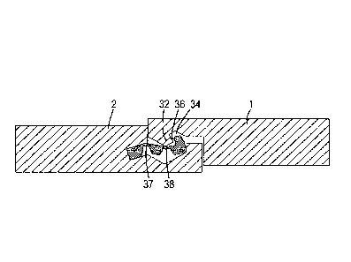
Figs. 3 and 4 show first and second edges 5, 6 of the
panels 1, 2 with the first and second joining members 11, 12
enabling the edges to be coupled to each other.
It is shown in the drawings that the second joining
member 12 of the second panel 2 is provided with a separate
locking element 20 which is fixed to the second joining member
12, but which has sufficient freedom of movement to move or
deform in order to cooperate with the first joining member 11 in
order to couple the joining members 11, 12 to each other such
that it locks the first and second joining members 11, 12 to
each other in both a direction perpendicular to the upper
surface 9 and in a direction parallel to the upper surface 9 but
perpendicular to the adjacent first and second edges 5, 6 in
their joined position. For this purpose, the locking element 20
is deformable from a first position, allowing first and second
joining members 11, 12 to be joined, to a second position in
which it locks the first and second joining members 11, 12 to
each other.
In the embodiment shown, the locking element 20 is
provided with a fixing portion 21 on one of its ends, a locking
portion 22 on its other, free, end and with a control portion 23
CA 02786768 2012-07-11
WO 2011/085825 PCT/EP2010/054993
12
in between. The locking element 20 may extend along the whole
length of the first edge 5, but preferably there are provided a
plurality of short locking elements 20 distributed along the
length of the edge 5, or even only one short locking element 20
substantially in the middle of the second edge 6. The length and
placement of the locking element 20 depends on various factors,
in particular the length of the edges 5, 6, the material of the
panels and the particular use of the panel assembly. The use of
one or more narrow locking elements facilitate a connection
between two panel edges when the edges are moved towards each
other in a non-parallel orientation, for example, if one panel
is folded down. Also the locking effect is better when there is
a high local load because if one locking element is disengaged
due to the high local load, the other locking elements will
remain locked and keep the edges together.
The fixing portion 21 of the locking element 20 is
fixed, in particular before delivery, for example glued or
clamped into a groove 24 which may extend along the whole edge 6
of the panel and may be inclined at an angle, in this case of
about 20 with respect to the lower surface 10 of the panel. The
groove 24 ends on the upper side at a vertical wall surface 25
adjacent to the upper surface 9 of the panel which in the joined
position of the edges 5, 6 is in contact with a vertical wall
surface 26 of the first edge 5. In the joined position, these
wall surfaces 25, 26 (which may also be non-vertical) form a
seam near the upper surface 9 of the panel.
The panel portion below the fixing groove 24 is
extended into a protruding lip 27 including in its upper surface
a depression 28 adjacent to groove 24. In the embodiment shown,
the depression 28 has a V-shaped configuration with the bottom
parallel to the edge 6. On its free end the lip is provided with
an upper projection 29 having an upright wall surface 30
bordering the depression 28. On the free end of the lip 27
remains a free space 31 to the first edge 5 of the other panel
in order to ensure that the seam between the vertical wall
surfaces 25, 26 near the upper surface 9 of the panels can be
closed.
CA 02786768 2012-07-11
WO 2011/085825 PCT/EP2010/054993
13
The first or male vertical joining member 11 comprises
a downward protrusion 32 having a substantially V-shaped lower
surface, the lower crest of which extends parallel to the first
edge 5 and is vertically aligned with the lowest point of the V-
shaped depression 28 when the first and second joining members
11 and 12 are in their coupled condition. The crest of the
protrusion forms the lowest point of the first joining member
where the distance from the upper surface 9 of the panel is at a
maximum. On the lower side of the first edge 5 is a recess 33
which is sufficiently large to take up the lip 27 of the female
joining member 12 in the coupled condition of the joining
members 11, 12. The edge 5 of a panel may or may not rest on the
upper side of projection 29 at the edge 6 of the adjacent panel.
The protrusion 32 has on its side facing away from the
vertical wall surface 26 and at a distance from the crest of the
protrusion a recess 34 having a locking surface 35 adapted to
cooperate with a locking surface 36 on the locking portion 22 of
the locking element 20. The locking surface 35 is inclined with
respect to the upper surface 9 and the vertical wall surface 26.
The angle may vary with respect to the upper surface 9 of the
panel.
As is clearly shown in Figs. 3 and 4, the locking
element 20 comprises two hinges 37 and 38 parallel to the second
edge 6 of the respective panel and enabling the locking element
20 to deform. The hinge 37 is positioned between the fixing
portion 21 and the control portion 23 of the locking element 20,
while the hinge 38 is positioned between the locking portion 22
and the control portion 23. As noted above, the locking portion
22 is provided with the locking surface 36, which is at an
acute, in the present case at a right angle to an adjacent
surface of the locking portion, and which is oriented
substantially vertically in the first position of the locking
element 20.
The hinges 37 and 38 are film hinges formed in one
piece with the locking element 20 and having a substantially
diminished thickness with respect to the adjacent portions of
the locking element 20, thereby allowing an elastic/plastic
CA 02786768 2012-07-11
WO 2011/085825 PCT/EP2010/054993
14
deformation of the locking element at the position of the hinges
37, 38.
The operation of the joining members 11, 12 is as
follows.
When panel 1 is in the position according to Fig. 1,
edge 5 and therefore joining member 11 of first panel 1 comes
gradually in engagement with edge 6 and joining member 12 of
panel 2. In one cross section, the panels 1, 2 may be in the
relative position according to Fig. 4a. The locking element 20
is in its first position with the upper side of the control
portion 23 and an adjacent surface of the locking portion 22
substantially horizontal. The lower side of the control portion
23 and a part of the locking portion adjacent to the hinge 38 is
at a distance from the underlying portion of the second joining
member 12, i.e. the depression 28 in the lip 27. This enables a
deformation of the locking element 20 and downward rotation of
the control portion 23 of the locking element 20. The locking
portion 22 is at a position distant from the hinge 38 in
engagement with the underlying second joining member 12, i.e.
the depression 28 adjacent to the upright wall surface 30. This
engagement prevents a complete downward movement of the locking
portion 22 as a result of the downward rotation of the control
portion 23, but allows a rotation of the locking portion 22 with
the hinge 38 moving downward.
The downward deformation of the locking element 20 is
caused by the downward movement of the first joining member 11
and the engagement of the crest of the protrusion 32, acting as
a control portion of the first joining member 11, with the
control portion 23 of the locking element 20 of the second
joining member 12 at a position near the hinge 38. The movement
of the protrusion, as seen in the cross section according to
Figs. 4b and 4c, is substantially perpendicular to the main
portion of the locking element 20, which extends substantially
horizontal in the first position, so that the locking element is
easily deformed by the protrusion 32. The control portion 23
rotates downwardly around the hinge 37, and the locking portion
22 rotates upwardly around the hinge 38. This rotation of the
CA 02786768 2012-07-11
WO 2011/085825 PCT/EP2010/054993
locking portion also causes a rotation of the locking surface,
and during the downward movement of the protrusion 32 of the
first joining member 11, the free end of the locking element 20
with the locking surface 36 rotates into the recess 34 in the
5 protrusion 32, such that finally in the second position of the
locking element 20 according to Fig. 4d, the locking surfaces 35
and 36 abut. As is clear, there is a movement substantially in
one direction only when the locking element 20 moves from the
first to the second position.
10 In the second position of the locking element 20, the
locking surface 36 thereof locks the first joining member 11 of
the first panel both in horizontal and vertical direction. The
crest of the protrusion is positioned substantially at the hinge
38 and vertically in line with the bottom of the depression 28,
15 so that the locking elements takes up the same V-shape as that
of the depression and Lhe lower side of the protrusion 32. In
the second position of the locking element 20, the lower and
upper sides thereof are in contact with the surface of the
depression 28 and protrusion 32, respectively, and are held in
contact due to the lock of the locking element 20.
This lock will be stronger if more force is needed to
disengage the locking surfaces 35 and 36 again. This can be
obtained for example if the friction between the locking
surfaces 35 and 36 is large or if the locking element 20 is
snapped into the recess 34. A proper dimensioning of the joining
members 11, 12 may realise this, for example curving the
surfaces or by dimensioning the parts such that the joining
element 20 must be stretched in order to allow engagement of the
locking element into the recess 34. Also if a return movement of
the hinges 37, 38 is hindered or requires a force, the unlocking
of the joining members 11, 12 will be disabled or hindered. If a
return upward movement of the first joining member 11 is
prevented, the disassembly of the panels 1 and 2 may be
accomplished by sliding one panel with respect to the other
along the edges 5, 6.
Fig. 5 shows a variation of the invention, in which the
locking element 20 is used to lock two panels 1 and 2 to each
CA 02786768 2012-07-11
WO 2011/085825 PCT/EP2010/054993
16
other when the first and second edges are moved towards each
other in a direction substantially parallel to the upper sides 9
and 10 of the panels 1 and 2 and substantially perpendicular to
the edges 5 and 6. The locking element 20 and the parts
cooperating with it are similar to that in Figs. 1 - 4, only the
orientation of these parts have been rotated 90 so that the
locking element 20 opens up in horizontal direction and can
receive the male joining member 11 when it is moved towards the
female locking member 12 and locking element 20 in horizontal
direction. The locking surfaces 35, 36 of the locking element 20
and of the male joining member 11 prevent a movement of the
second edge 6 in upward direction and in a direction away from
the first edge 5. Horizontal surfaces 39, 40 of the first and
second edges which abut when the first and second edges 5, 6
engage prevent an upward movement of the first edge 5. This
locking action could also be provided by a second locking
element turned upside down. Other variations are conceivable.
Figs. 6 - 10 show a third embodiment similar to that of
Figs. 1 - 4, but in which the first and second locking surfaces
35, 36 of the locking element 20 and of the male joining member
11 lock the first and second edge 5, 6 of the panels 1 and 2 in
cooperation with third and fourth locking surfaces 41, 42 on the
male and female joining members 11, 12.
Figs. 9a and 9b most clearly show the resemblance of
the locking element 20. In this embodiment, and this may also be
the case in the first and second embodiment, the locking element
20 is fit between the groove 24 and the wall 30 such that the
locking element is stable in the first and second positions as
shown, but must be pushed with force through an, unstable,
intermediate position where the direction of a pretension is
reversed. This is caused by the fact that the length of the
locking element 20 is larger than the distance between the
groove 24 and the wall 30. The hinges 37 and 38 enable a
deformation of the locking element 20 through the intermediate
position. Due to this construction, the locking element 20 will
be forcibly held in the second position and is able to
effectively lock the male joining member 11. The locking element
CA 02786768 2012-07-11
WO 2011/085825 PCT/EP2010/054993
17
20 is formed at the position where the upright wall 30 and the
depression 28 meet as a pivot to guide the pivoting movement of
the locking portion 22 of the locking element. Other click or
snap constructions are possible of course.
In this third embodiment it is shown that the locking
surface 35 of the male joining member 11 is substantially
vertical, so that when it is in engagement with the locking
surface 36 of the locking element 20, it will only be held in
horizontal direction, i.e. in a direction parallel to the upper
sides 9, 10 of the panels 1, 2. The lock in a direction
perpendicular to the upper sides is in this case effected by the
third and fourth locking surfaces 41, 42 mentioned above. The
third locking surface is formed on the upper side of a tongue 43
which protrudes from the vertical surface 26 and adjacent to the
downward protrusion 32 on the first edge S. The angle of the
third locking surface 41 to the upper side is approximately 45 ,
but may vary as long as there is a horizontal component to
prevent an upward movement of the edge 5 when the locking
element 20 is in the second locking position.
The fourth locking surface 42 is formed at an undercut
adjacent to the vertical surface 25 on one side and to the
fixing groove 24 on the other side. The angle of the fourth
locking surface 42 is substantially equal to that of the third
locking surface, but this is not required. The third and fourth
locking surfaces 41, 42 may also be positioned in other places.
From Figs. 9a, 9b it becomes clear that in the first
position of the locking element 20 according to Fig. 9a, the
locking portion 22 is pivoted away from the vertical wall
surface 25, so that a large opening for the protrusion 32 of the
male joining member 11 is formed and it is thus easy to enter
the protrusion 32 in a substantially vertical direction. The
protrusion 32 will meet the control portion 23 of the locking
element 20 substantially at the same time as the third and
fourth locking surfaces 41, 42 come into contact. When the
control portion 23 of the locking element is pushed down, the
locking portion 22 will pivot and therefore the locking surface
35 will move in the direction towards the vertical surface 25
CA 02786768 2012-07-11
WO 2011/085825 PCT/EP2010/054993
18
and will thus horizontally push against the locking surface 36
and thereby move the whole panel 1 horizontally so that the
third and fourth locking surfaces 41, 42 fully come into
engagement until the vertical surfaces 25, 26 meet and the male
joining member is fully pushed down. The locking element 20 is
pushed through the intermediate position and is now pre-
tensioned to keep the locking surfaces 35, 36 and therefore also
the vertical surfaces 25, 26 forming the seam between the panels
1 and 2 in abutment preventing the formation of a gap there.
As becomes clear from Figs. 10a and 10b, the locking
element 20 is provided with a stop 44 determining the end
position of the protrusion of the male joining member 11. It is
placed on a side of the locking element 20 which extends only
along a part of the length of the edge 5.
Figs. 6 - 8 show that a great number of locking
elements 20 and stops 44 are combined into a strip 45 which may
extend substantially the full length of the edge 5. A connecting
beam 46 forms at least a part of the fixing portions 21 of the
locking elements 20 and extends continuously along the strip 45
thereby connecting the locking elements 20 and the stops 44
which are arranged alternatingly. The stops 44 follow the groove
24 and the bottom of the depression 28 and are (press)fit
between the bottom of the groove 24 and the upright wall 30. To
compensate for tolerances, the strip 45 may be slightly
compressible at the bottom of the groove 24, for example by
means of a notch or cut from above to form a finger at the end
of the stop 44.
Fig. 11 shows a variation of the third embodiment in
which the stops 44 are also connected to each other on the edge
opposite to the beam 46 by means of a beam 47 making the strip
more stable against warping and other deformations. The function
of the upright wall 30 is now taken over or complimented by this
beam 47.
Figs. 12a and 12b show another variation of the
embodiment of Figs. 6 - 10. In this variation, there are
provided additional means to maintain the locking element 20 and
the male joining member 11 in their second position. For this
CA 02786768 2012-07-11
WO 2011/085825 PCT/EP2010/054993
19
purpose, the protrusion 32 of the male joining member 11 is
provided with a nose portion 48 having an engagement surface 49
adapted to come into engagement surface 50 on the stop 44. The
engagement surfaces can be made mainly parallel to the locking
surfaces 41 and 42, respectively, and assist in keeping the male
and female joining members 11, 12 in engagement with each other,
both in horizontal and vertical direction. The nose portion 48
extends along the whole length of the male joining member 11,
and the locking elements 11 are shaped to allow the engagement
surfaces 49 and 50 to come into engagement without blocking the
downward movement of the male joining member 11.
Furthermore the locking element 20 and the lip 27 of
the female joining member 12 are provided with engagement
surfaces 51 and 52 which act more or less as snap members such
that the engagement surface 51 of the locking member 20 hooks
behind the engagement surface 52 of the lip 27. These engagement
surfaces are particularly useful in case the dimensions are such
that it is not possible to push the locking element sufficiently
downwards through the intermediate position as described above
in relation to Figs. 6 - 10. This may for example be the case
with thin panels, for example below 7 mm. In general, the lock
will be light so that the surfaces 51 and 52 can be easily
disengaged when a panel should be removed.
In Fig. 12 it is also visible that the locking elements
20 and the remainder of the strip 45 are formed separately.
First the locking elements 20 are formed, preferably by
injection molding, and then the locking elements are placed in a
second mould in which the remainder of the strip 45 is formed
during which the plastic of the strip 45 is moulded around the
end of the locking elements 20 near the fixing portion 21 so
that an integral strip 45 is formed. Generally the complete
strip 45 is made from the same material, for example
polypropylene to obtain good deformation properties, but it is
also possible to form the locking elements 20 from different
material than the remainder of the strip 45. The connection
between the locking elements 20 and the remainder of the strip
CA 02786768 2012-07-11
WO 2011/085825 PCT/EP2010/054993
45 is mechanical, i.e. by a shape lock, but a chemical bond is
conceivable as well.
It is noted that aspects of the various embodiments as
shown and described may be used in different combinations. The
5 invention is not limited to the embodiments shown in the drawing
and described above, which may be varied in different ways
within the scope of the invention. For example, it would be
possible to use the invention with panels that have vertical
joining members on all four sides and that can thus be laid by
10 moving the panels vertically with respect to one, two or more
panels already installed. Furthermore, it would be conceivable
that the locking element has separate surfaces to lock the
vertical joining members in two different directions. Although
the locking element has been described before as an element that
15 is separate from the panels, it could be integrated in one of
the panels, especially if the panels are made from plastic
material. It is also possible that each of the first and second
joining members has its own locking element co-operating with
the other one. Both locking elements could be deformable or only
20 one. It is also conceivable that the single locking element only
locks the panels in cooperation with other locking means, such
as ridges, tongues and grooves, hooks and undercuts and the
like. The panels may have a different configuration than
substantially rectangular, in particular triangular or
hexagonal. The panel edges should be configured such that
adjacent panel edges have matching joining members.