Note: Descriptions are shown in the official language in which they were submitted.
CA 02787188 2012-08-20
INTEGRALLY STIFFENED, REUSABLE VACUUM BAG
AND METHOD OF MAKING THE SAME
BACKGROUND INFORMATION
1. Field:
The present disclosure generally relates to equipment used to fabricate
composite parts, and
deal more particularly with a vacuum bag used to compress composite part
layups.
2. Background:
Flexible vacuum bags may be used to process parts in a wide variety of
applications. In the
composites industry, vacuum bags are used to consolidate, laminate, mold or
bond composite parts
using a vacuum drawn within the bag to apply atmospheric pressure to the
parts. The bag comprises a
flexible membrane or diaphragm that may be an extruded polymer film such as
nylon.
. ,
Polymer film type vacuum bags are typically not re-usable and must be
discarded after each
use, thus representing a recurring production cost. Reusable type vacuum bags
are known which
employ a rubber coated fabric or film, however these types of bags, which
typically employ stiffening
structures, are relatively complex, heavy and relatively expensive to
fabricate. For example, reusable
elastomeric type vacuum bags are fabricated using metallic stiffening frames.
Separate bonding
operations are required to attach the bag diaphragm, seal and frame to each
other. Each component is
fabricated separately, and the tooling used to produce the bags must be
oversized in order to allow for
shrinkage of the bag diaphragm during fabrication.
Accordingly, there is a need for an improved, reusable, integrally stiffened
vacuum bag that
reduces the number of steps required for its fabrication, while reducing
weight and complexity of the
bag.
SUMMARY
The disclosed embodiments provide an integrally stiffened, reusable vacuum
bag, and related
method of making the same, which reduce the number of fabrication steps and
parts, thereby reducing
costs. The bag is integrally stiffened with a rigid, peripheral frame that is
encapsulated in the bag
diaphragm, thereby eliminating the need for a separate operation to join the
stiffener to the bag
diaphragm. A peripheral bag seal may be integrally formed with the bag
diaphragm, thereby
eliminating the need for a separate bonding operation to attach the seal to
the bag assembly. In one
embodiment, the reusable vacuum bag may be fabricated on the layup tool that
is used to layup and/or
cure a composite part, thus eliminating the need for a separate tool to
fabricate the vacuum bag.
Relatively large, lightweight reusable vacuum bags may be fabricated that
avoid the need for heavy
outer support frames.
1
CA 02787188 2012-08-20
According to one disclosed embodiment, a vacuum bag for processing parts is
provided
comprising a flexible diaphragm and a generally rigid frame. The diaphragm is
adapted to be placed
over a part, and the frame is encapsulated within the diaphragm. The bag may
comprise an
elastomeric material such as a room curable RTV silicone. The frame may
comprise a composite that
extends around the periphery of the diaphragm and has its sides covered by the
diaphragm. The
vacuum bag may further comprise a seal for sealing the diaphragm against a
surface during processing
of the part. The seal may be formed integral with the diaphragm or
alternatively, may be bonded to
the frame.
According to another disclosed embodiment, an integrally stiffened, reusable
vacuum bag for
processing parts comprises a flexible diaphragm having an integral stiffener
around its periphery. The
bag may further comprise a seal integral with and extending around the
periphery of the diaphragm
for sealing the diaphragm against the surface during processing of the part.
The stiffener may include
a generally rigid frame encapsulated in the diaphragm which may comprise a
vulcanized elastomer.
According to a further embodiment, a method is provided of making a vacuum bag
for
processing parts. The method comprises forming a flexible diaphragm, and
encapsulating a generally
rigid frame within the diaphragm. Forming the diaphragm may include coating a
tool surface with an
elastomer, and encapsulating the frame includes placing the frame on the
elastomer coating and
applying additional elastomer over the frame. The method may further comprise
forming a seal
integrally with the diaphragm. Forming the seal may include placing a seal
element on a tool surface,
and forming the diaphragm may include spraying a coating of elastomer over the
tool surface
covering the seal. The method may further comprise co-curing the seal and the
elastomer coating.
According to still another embodiment, a method is provided of making an
integrally
stiffened, reusable vacuum bag for processing parts. The method comprises
fabricating a generally
rigid frame, and forming a diaphragm by spraying a first coating of an
elastomer over a tool surface.
The method also comprises placing the frame on the diaphragm, and
encapsulating the frame with
elastomer by spraying a second coating of the elastomer over the frame and
onto the diaphragm. The
method also includes co-curing the first and second elastomer coatings. The
method may further
comprises placing a seal on the tool surface, wherein spraying the first
coating includes spraying the
elastomer over the seal, and co-curing the first and second coatings and the
seal.
In summary, according to one aspect of the invention there is provided a
vacuum bag for
processing a part, including a flexible diaphragm adapted to be placed over
the part; and a generally
rigid frame encapsulated within the diaphragm.
Advantageously the vacuum bag wherein the diaphragm is an elastomeric
material.
Advantageously the vacuum bag wherein the diaphragm is RTV silicone.
Advantageously the vacuum bag wherein the frame is a composite.
Advantageously the vacuum bag wherein the frame is encapsulated within the
diaphragm.
2
CA 02787188 2012-08-20
=
Advantageously the vacuum bag further including a seal for sealing the
diaphragm against a
surface during processing of the part.
Advantageously the vacuum bag wherein the seal is formed integral with the
diaphragm.
Advantageously the vacuum bag wherein the seal is attached to the encapsulated
frame.
Advantageously the vacuum bag wherein frame has sides surrounded by the
diaphragm.
According to another aspect of the invention there is provided an integrally
stiffened, reusable
vacuum bag for processing parts, including a flexible diaphragm having an
integral stiffener around
its periphery.
Advantageously the vacuum bag further including a seal integral with and
extending around
the periphery of the diaphragm for sealing the diaphragm against a surface
during processing of a part.
Advantageously the vacuum bag wherein the stiffener includes a generally rigid
frame
encapsulated in the diaphragm.
Advantageously the vacuum bag wherein the diaphragm is a vulcanized elastomer.
According to a further aspect of the present invention there is provided a
method of making a
vacuum bag for processing parts; including forming a flexible diaphragm; and
encapsulating a
generally rigid frame within the diaphragm.
Advantageously the method wherein forming the diaphragm includes coating a
tool surface
with an elastomer, and encapsulating the frame includes placing the frame on
the elastomer coating
and applying additional elastomer over the frame.
Advantageously the method further including forming a seal integral with the
diaphragm.
Advantageously the method wherein forming the seal includes placing a seal
element on a
tool surface, and forming the diaphragm includes spraying a coating of
elastomer over the tool surface
covering the seal.
Advantageously the method further including cocuring the seal and the
elastomer coating.
An embodiment according to a yet further aspect of the present invention there
is provided a
method of making an integrally stiffened, reusable vacuum bag for processing
parts, including
fabricating a generally rigid frame; forming a diaphragm by spraying a first
coating of an elastomer
over a tool surface; placing the frame on the diaphragm; encapsulating the
frame with elastomer by
spraying a second coating of the elastomer over the frame and onto the
diaphragm; and cocuring the
first and second elastomer coatings.
Advantageously the method further including placing a seal on the tool
surface, wherein
spraying the first coating includes spraying the elastomer over the seal; and
cocuring the first and
second coatings and the seal.
Advantageously the method further including forming the seal from an
elastomer.
Advantageously the method further including bonding the seal to the frame.
According to another aspect of the present invention there is provided a
method of making an
integrally stiffened, reusable vacuum bag for compressing a composite part
layup on a layup tool,
3
including forming a peripheral seal; placing the seal on the layup tool;
forming a flexible bag
diaphragm by spraying a coating of a room temperature curable RTV silicone
over the layup
tool covering the seal; fabricating a generally rigid frame; placing the frame
on the layup tool,
overlying the diaphragm and generally registered with the seal; encapsulating
the frame in the
diaphragm by spraying a coating of a room temperature curable RTV silicone
over the sides
of the frame and onto the diaphragm; vulcanizing the RTV silicone coatings at
room
temperature; attaching hardware to the frame; and installing the installing
the encapsulated
frame on the layup tool.
According to another aspect of the present invention there is provided an
integrally
stiffened, reusable vacuum bag for compressing a composite part layup on a
layup tool,
including a rigid composite frame having a bottom and at three sides; a
flexible bag
diaphragm formed of vulcanized RTV silicone extending across the bottom of the
frame and
encapsulating the three sides of the frame; and a seal formed of RTV silicone
for sealing the
bag diaphragm against the layup tool, the seal being integral with the bag
diaphragm and
located beneath the bottom of the frame.
According to another aspect of the invention there is provided a vacuum bag
for
processing a part, comprising: a generally planar flexible diaphragm adapted
to be placed over
the part; a generally rigid frame encapsulated within the diaphragm; and a
seal connected to a
lower surface of the diaphragm, wherein the seal is arranged for sealing the
diaphragm against
a surface of a tool upon which the part is positioned during processing of the
part, thereby
allowing a vacuum to be drawn within the bag.
According to another aspect of the invention there is provided a method of
making a
vacuum bag for processing parts, comprising: forming a seal; forming a
generally planar
flexible diaphragm over an upper surface of a tool, wherein a lower surface of
the diaphragm
faces the upper surface of the tools connecting the seal to the lower surface
of the diaphragm;
and encapsulating a generally rigid frame within the diaphragm, wherein the
seal is arranged
for sealing the diaphragm against a surface of a tool upon which a part is
positioned during
processing, thereby allowing a vacuum to be drawn within the bag.
4
CA 2787188 2018-12-11
According to another aspect of the invention there is provided a vacuum bag
for
processing a part, comprising: a flexible diaphragm adapted to be placed over
the part, the
flexible diaphragm comprising RTV silicone; a frame having a plurality of
sides and the
diaphragm disposed so as to completely encapsulate the frame and contacting
each of the
plurality of sides, the frame being substantially planar; and a seal connected
to the diaphragm,
the seal configured to seal the diaphragm against a surface of a tool upon
which the part is
positioned such that a vacuum drawn between the diaphragm and the surface
compresses the
part against the tool, the seal positioned substantially between the frame and
the tool, and the
scal being cocured with the diaphragm.
According to another aspect of the invention there is provided a reusable
vacuum bag
for processing parts, comprising: a flexible diaphragm configured to press
against a surface of
a part, the diaphragm being substantially planar and comprising RTV silicone;
a rigid frame
comprising a plurality of walls, the diaphragm completely encapsulating and
contacting each
of the plurality of walls; and a seal connected to the diaphragm, the seal
configured to provide
sealing against a tool, the seal positioned between the frame and the tool,
and the seal being
cocured with the diaphragm.
According to still yet another aspect of the invention there is provided an
assembly
for compressing a composite part layup on a layup tool, comprising: a
composite frame
having a bottom and at least three sides, the frame being substantially rigid,
planar, and
rectangular; a flexible bag diaphragm formed of vulcanized RTV silicone
extending across
the bottom of the frame; an encapsulation comprising RTV silicone completely
encapsulating
the composite frame and contacting the bottom and the at least three sides of
the composite
frame; a layup tool, the composite part layup resting on the layup tool; and a
seal formed of
RTV silicone sealing the flexible bag diaphragm against the layup tool, the
seal being integral
with the bag diaphragm and located beneath the bottom of the frame and the
seal, the flexible
bag diaphragm, and the encapsulation being cocured.
4a
CA 2787188 2018-12-11
BRIEF DESCRIPTION OF THE DRAWINGS
The novel features believed characteristic of the advantageous embodiments are
set
forth in the appended claims. The advantageous embodiments, however, as well
as a preferred
mode of use, further objectives and advantages thereof, will best be
understood by reference
to the following detailed description of an advantageous embodiment of the
present disclosure
when read in conjunction with the accompanying drawings, wherein:
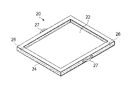
FIG. 1 is an illustration of a perspective view of an integrally stiffened,
reusable
vacuum bag according to the disclosed embodiments.
FIG. 2 is an illustration of a sectional view of an edge of a composite layup
assembly,
showing the bag installed over a composite part layup on a tool.
FIG. 3 is an illustration of a perspective view of a tool used to make the
vacuum bag
shown in FIGS. 1 and 2.
FIG. 4 is an illustration of a flow diagram showing the steps of a method of
making a
reusable vacuum bag having an integrated seal.
FIG. 5 is an illustration of a perspective view of a stiffening frame prior to
being
assembled with the bag.
FIGS. 6-11 are illustrations of cross sectional views diagrammatically showing
the
sequential steps of the method of FIG. 5.
FIG. 12 is an illustration of a flow diagram showing the steps of an alternate
method
of making a reusable bag having a bonded seal.
FIGS. 13-17 are illustrations of cross sectional views diagrammatically
showing the
sequential steps of the method of FIG. 12.
FIG. 18 is an illustration of a flow diagram of aircraft production and
service
methodology.
4b
CA 2787188 2018-12-11
CA 02787188 2012-08-20
FIG. 19 is an illustration of a block diagram of an aircraft.
DETAILED DESCRIPTION
Referring first to FIGS. 1 and 2, the disclosed embodiments relate to an
integrally stiffened,
reusable vacuum bag 20 that may be used, for example and without limitation,
to consolidate and/or
compress a composite part 34 on a tool 30. The bag 20 includes a generally
planar, elastic bag
diaphragm 22 having dimensions that are suited to the particular application,
covering the part 34.
The bag 20 also includes an outer frame 24 and a peripheral seal 26 beneath
the frame 24 which seals
the bag diaphragm 22 against a tool surface 28. rfhe frame 24 may be
manufactured of any suitable
rigid or semi-rigid material, such as a composite or a lightweight metal, and
may be provided with
attachments such as handles 27 to aid in handling or manipulating the bag 20.
In the illustrated
embodiment, the frame 24 is generally rectangular, however it may have other
shapes that are suited
to the geometry of the composite part 34 being processed. The frame 24 has a
generally rectangular
cross section, as shown in FIG. 2, however other cross sectional shapes are
possible.
The diaphragm 22 extends outwardly across the bottom 67 of the frame 24, and
encapsulates
32 the sides 68, 72 and top 70 of the frame 24. Encapsulation 32 of the frame
24 within the
diaphragn 22 essentially provides the elastic diaphragm 22 with integral
stiffening that allows the bag
to be easily handled and manipulated. The seal 26 extends around the entire
periphery of the
composite part 34 and creates an air tight seal between the bag diaphragm 22
and the upper surface 28
of the tool 30, allowing a vacuum to be drawn within the bag 22. As will be
discussed below, in one
20
embodiment, the seal 26 is formed integral with the bag 22, while in another
embodiment, the seal 26
is bonded to the frame 24 in a separate fabrication operation.
Referring to FIG. 3, in one method embodiment, the vacuum bag 20 is fabricated
using a tool
36 having a generally flat tool surface 38 and a peripheral groove 40. In
other embodiments, the
vacuum bag 20 may be fabricated using the same tool 30 that is used to process
the composite part 34.
Attention is now directed to FIG. 4, along with FIGS. 5-11 which sequentially
illustrate the
steps of one method of fabricating the vacuum bag 20 shown in FIGS. 1 and 2.
Beginning at step 42,
the frame 24 is fabricated (FIG. 5) using any of various fabrication
techniques, including laminating
and curing prepreg fiber. Where the frame 24 is formed of the composite, it
may be laid up on either
tool 30 (FIG. 2) or tool 36 (FIG. 3). Next, at step 44, a peripheral seal 26
is fabricated using a suitable
elastic material such as an elastomer that is molded or extruded into the
desired cross section. As
used herein, "elastomer" and "elastomeric" refer to natural and synthetic
polymers that exhibit elastic
properties, similar to natural rubber. For example, and without limitation,
the elastomer may
comprise a thermoset or a thermoplastic that can stretch and return
substantially to its original shape
without material deformation. At step 44 the seal 26 may be placed in a groove
40 (FIG. 6) of tool 36
such that the seal 26 is generally coplanar with the upper surface 38 of the
tool 36. The groove 40
assists in holding and stabilizing the seal 26 during subsequent processing
steps. Alternatively, as
shown in FIG. 7, where the vacuum bag 20 is fabricated directly on the layup
tool 30 used to fabricate
5
CA 02787188 2012-08-20
the composite part 34 (FIG. 2), shims 58 may be placed on the tool surface 28
surrounding the seal 26
in order to stabilize and hold the seal 26 during subsequent processing
operations.
Referring now again to FIG. 4, the diaphragm 22 (FIG. 8) is formed by applying
a first
elastomeric coating 64 over the surface 38 of tool 36. The application of the
first coating 64 may be
performed by spraying 60 an elastomer from a spray head 62 over tool surface
38. The first coating
64 extends over the seal 26. In one embodiment, the first elastomeric coating
64 may comprise a
sprayable, RTV catalyzed silicone, which may be a one or two part system that
cures relatively
quickly at room temperature, without the need for oven or autoclave
processing, and exhibits little or
no shrinkage following curing. Other forms of elastomers are possible, some of
which may require
curing at elevated temperatures using an oven or other suitable heating
devices. In one embodiment,
the seal 26 is formed from an elastomer that is substantially identical to the
elastomer used in the first
elastomeric coating 64 forming the diaphragm 22. Other techniques for applying
the first coating 64
may be used, including but not limited to extrusion.
At step 50 (FIG. 4), the frame 24 is placed on the diaphragm 22, as shown in
FIG. 9, with the
frame bottom 67 generally overlying and registered with the peripheral
position of the seal 26. Next,
at step 52 in FIG. 4, the frame 24 is encapsulated 32 (FIG. 10) with an
elastomer, by applying, as by
spraying 60 a second elastomeric coating 66 over the exposed sides 68, 72 and
top 70 of the frame 24.
The second coating 66 extends over onto the first coating 64 previously
applied. Thus, in this
embodiment, the diaphragm 22 along with the seal 26 and the encapsulation 32
on the frame 24 are
formed of substantially the same material, which at this point in the
fabrication process, are uncured.
At step 54, optionally, suitable hardware or handling attachments, such as
handles 27 shown in FIG.
1, may be attached to the frame 24. Finally, at step 56 shown in FIG. 4, the
diaphragm 22, frame
encapsulation 32 and the seal 26 are cocured or vulcanized through the
application of heat 74. As
previously discussed, where a suitable RTV silicone elastomer is used, the
heat 74 may comprise
room temperature heat. Cocuring integrates the diaphragm 22, the encapsulation
32 around the frame
24 and the seal 26 into a continuous, unitary viscoelastic structure.
Attention is now directed to FIG. 12 which, along with FIGS. 13-17,
illustrates the steps of
another method of fabricating the vacuum bag 20. At 76, a suitable frame 24 is
fabricated following
which at 78 a diaphragm 22 (FIG. 13) is formed by applying an elastomeric
coating 64 over the tool
surface 38, either by spraying 60, extruding or other application techniques.
Next, at step 80, the
frame 24 (FIG. 14) is placed on the outer periphery of the diaphragm 22, in
contact with the first
elastomeric coating 64. At step 82, the frame 24 is encapsulated 32 by
applying a second elastomeric
coating 66 over the sides 68, 72 and top 70 of the frame 24, as shown in FIG.
15. The second coating
66 may be applied as by spraying 60, from a spray head 62 or by using other
techniques including but
not limited to extrusion. The second coating 66 both covers the sides 68, 72
and top 70 of the frame
24, and joins with and overlies the first coating 64, forming a substantially,
one-piece, unitary
structure following curing.
6
CA 02787188 2012-08-20
At step 84 shown in FIG. 12, the diaphragm 22 along with the encapsulation 32
surrounding
the frame 24 are cured (FIG. 16) by applying heat 74 to the elastomer coatings
64, 66. As previously
mentioned as in connection with the embodiments shown in FIGS. 4-11, the
elastomer may comprise
an RTV silicone that cures at room temperature. At step 86 suitable hardware
or attachments 22 may
be installed on the frame 24 as previously described. At step 88 shown in FIG.
12, a seal 26 (FIG. 17)
is bonded to the lower surface 24a of the diaphragm 26, beneath the frame 24,
using any suitable
techniques, such as using a bonding adhesive. The seal 26 may or may not be
formed of a material
that is the same as that of the diaphragm 26.
Embodiments of the disclosure may find use in a variety of potential
applications, particularly
in the transportation industry, including for example, aerospace, marine,
automotive applications and
other application where automated layup equipment may be used. Thus, referring
now to FIGS. 18
and 19, embodiments of the disclosure may be used in the context of an
aircraft manufacturing and
service method 90 as shown in Figure 18 and an aircraft 92 as shown in Figure
19. Aircraft
applications of the disclosed embodiments may include, for example, without
limitation, layup of
stiffener members such as, without limitation frames, stiffeners, hatches,
spars and stringers, to name
only a few. During pre-production, exemplary method 90 may include
specification and design 94 of
the aircraft 92 and material procurement 96. During production, component and
subassembly
manufacturing 98 and system integration 100 of the aircraft 92 takes place.
Thereafter, the aircraft 92
may go through certification and delivery 102 in order to be placed in service
104. While in service
by a customer, the aircraft 92 is scheduled for routine maintenance and
service 106, which may also
include modification, reconfiguration, refurbishment, and so on.
Each of the processes of method 90 may be performed or carried out by a system
integrator, a
third party, and/or an operator (e.g., a customer). For the purposes of this
description, a system
integrator may include without limitation any number of aircraft manufacturers
and major-system
subcontractors; a third party may include without limitation any number of
vendors, subcontractors,
and suppliers; and an operator may be an airline, leasing company, military
entity, service
organization, and so on.
As shown in FIG. 19, the aircraft 92 produced by exemplary method 90 may
include an
airframe 108 with a plurality of systems 110 and an interior 112. Examples of
high-level systems 110
include one or more of a propulsion system 114, an electrical system 116, a
hydraulic system 118, and
an environmental system 120. Any number of other systems may be included.
Although an
aerospace example is shown, the principles of the disclosure may be applied to
other industries, such
as the marine and automotive industries.
Systems and methods embodied herein may be employed during any one or more of
the
stages of the production and service method 90. For example, components or
subassemblies
corresponding to production process 98 may be fabricated or manufactured in a
manner similar to
components or subassemblies produced while the aircraft 92 is in service.
Also, one or more
7
CA 02787188 2012-08-20
apparatus embodiments, method embodiments, or a combination thereof may be
utilized during the
production stages 98 and 100, for example, by substantially expediting
assembly of or reducing the
cost of an aircraft 92. Similarly, one or more of apparatus embodiments,
method embodiments, or a
combination thereof may be utilized while the aircraft 92 is in service, for
example and without
limitation, to maintenance and service 106.
The description of the different advantageous embodiments has been presented
for purposes
of illustration and description, and is not intended to be exhaustive or
limited to the embodiments in
the form disclosed. Many modifications and variations will be apparent to
those of ordinary skill in
the art. Further, different advantageous embodiments may provide different
advantages as compared
to other advantageous embodiments. The embodiment or embodiments selected are
chosen and
described in order to best explain the principles of the embodiments, the
practical application, and to
enable others of ordinary skill in the art to understand the disclosure for
various embodiments with
various modifications as are suited to the particular use contemplated.
8