Language selection

Search

Patent 2787519 Summary

Third-party information liability

Some of the information on this Web page has been provided by external sources. The Government of Canada is not responsible for the accuracy, reliability or currency of the information supplied by external sources. Users wishing to rely upon this information should consult directly with the source of the information. Content provided by external sources is not subject to official languages, privacy and accessibility requirements.

Claims and Abstract availability

Any discrepancies in the text and image of the Claims and Abstract are due to differing posting times. Text of the Claims and Abstract are posted:

  • At the time the application is open to public inspection;
  • At the time of issue of the patent (grant).
(12) Patent Application: (11) CA 2787519
(54) English Title: A COUPLING APPARATUS WITH TWO COUPLINGS
(54) French Title: ACCOUPLEMENT ELASTIQUE
Status: Deemed Abandoned and Beyond the Period of Reinstatement - Pending Response to Notice of Disregarded Communication
Bibliographic Data
(51) International Patent Classification (IPC):
  • F16D 3/68 (2006.01)
(72) Inventors :
  • MISTLBAUER, WALTER (Austria)
(73) Owners :
  • VOITH PATENT GMBH
(71) Applicants :
  • VOITH PATENT GMBH (Germany)
(74) Agent:
(74) Associate agent:
(45) Issued:
(86) PCT Filing Date: 2010-11-06
(87) Open to Public Inspection: 2011-07-28
Availability of licence: N/A
Dedicated to the Public: N/A
(25) Language of filing: English

Patent Cooperation Treaty (PCT): Yes
(86) PCT Filing Number: PCT/EP2010/006763
(87) International Publication Number: WO 2011088860
(85) National Entry: 2012-07-19

(30) Application Priority Data:
Application No. Country/Territory Date
10 2010 005 255.8 (Germany) 2010-01-20

Abstracts

English Abstract

The invention relates to an elastic coupling, comprising a primary part; comprising a secondary part; the primary part and secondary part being rotatable relative to each other to a limited extent against the force of springs; the springs comprising plate-shaped spring plates made of rubber-elastic material; support plates being arranged between the spring plates; a plurality of carriers for carrying the spring plates and the support plates being distributed over the circumference of the coupling. The invention is characterized by the following features: each carrier has the contour of a wedge tapered radially inward, as viewed from above along the coupling axis; a packet of alternating spring plates and support plates is located on both sides of each carrier, said packets being adjacent to the two wedge surfaces of the carrier.


French Abstract

L'invention concerne un accouplement élastique comprenant une partie primaire et une partie secondaire. La partie primaire et la partie secondaire pouvant être entraînées en rotation de façon limitée l'une par rapport à l'autre à l'encontre de la force de ressorts, les ressorts comprenant des plaques élastiques en forme de plaque constituées d'un matériau en caoutchouc élastique. Des plaques d'appui sont disposées entre les plaques élastiques. Plusieurs supports destinés à soutenir les plaques élastiques et les plaques d'appui sont répartis sur la périphérie de l'accouplement. L'invention est caractérisée en ce que : chaque support présente - dans une vue en élévation de l'axe d'accouplement- le contour d'un coin se rétrécissant radialement vers l'intérieur ; de part et d'autre de chaque support se situe de manière adjacente aux deux surfaces cunéiformes du support un paquet de plaques élastiques et de plaques d'appui en alternance.

Claims

Note: Claims are shown in the official language in which they were submitted.

9
CLAIMS:
1. An elastic coupling (1, 10)
1.1 with a primary part;
1.2 with a secondary part;
1.3 the primary part and the secondary part are twistable to a certain extent
relative to one another against the force of springs;
1.4 the springs comprise plate-shaped spring plates (8) made of rubber-elastic
material;
1.5 support plates (9) are arranged between the spring plates (8);
1.6 several carriers (4) for carrying the spring plates (8) and the support
plates
(9) are arranged in a distributed manner over the circumference of the
coupling, characterized by the following features:
1.7 when seen in a top view of the coupling axis, each carrier (4) has the
contour of a wedge which tapers radially inwardly;
1.8 a packet of spring plates (8) and support plates (9) is disposed in an
alternating manner on either side of each carrier (4) adjacent to the two
wedge surfaces of the carrier.
2. An elastic coupling according to claim 1, characterized in that the spring
packets, which comprise the spring plates (8) and the support plates (9),
are components which are separate from the carriers (4).
3. An elastic coupling according to claim 1, characterized in that every
carrier
(4) forms a premounted structural unit together with the associated spring
packets.
4. An elastic coupling according to one of the claims 1 to 3, characterized in
that the support plates (9) which are the outer ones as seen in the
circumferential direction comprise a guide strip (20) or a guide groove (21),

which cooperate with a respective guide strip or guide groove of the spring
packets of the other coupling part.
5. An elastic coupling according to one of the claims 1 to 4, comprising the
following features:
5.1 as seen in the direction of the coupling axis (5), the coupling comprises
a
star-shaped base body (3);
5.2 the base body (3) comprises a plurality of projections (3.1) extending
radially to the outside;
5.3 every projection (3.1) carries a carrier (4);
5.4 every carrier (4) is fixed to the associated projection (3.1) by means of
two
screws (6, 6);
5.5 there is a locating pin (7) between the two screws (6, 6) for positioning
the
carrier (4), which locating pin is axially parallel with respect to the screws
(6, 6).
6. A coupling apparatus for transmitting a torque from a drive shaft to an
output shaft, comprising the following features:
6.1 two couplings (1, 10) according to one of the claims 1 to 5 are provided;
6.2 the one (1) of the two couplings is in a drive connection with the drive
shaft, and the other (10) of the two couplings is in a drive connection with
the output shaft;
6.3 the secondary part of the first coupling (1) is in drive connection via a
spacer shaft with the primary part of the second coupling (10).
7. A coupling apparatus according to claim 6, characterized in that the spacer
shaft is a hollow shaft.
8. A method for mounting an elastic coupling according to claim 5,
characterized by the following method steps:

11
8.1 the locating pin (7) is inserted into the carrier (4);
8.2 the unit comprising the carrier (4), the spring plates (8) and the support
plates (9) will be mounted on the base body (3).

Description

Note: Descriptions are shown in the official language in which they were submitted.


CA 02787519 2012-07-19
1
A coupling apparatus with two couplings
The invention relates to an elastic coupling with a primary part and a
secondary
part which can be twisted relative to one another to a limited extent against
the
force of springs. The invention further relates to a method for mounting such
a
coupling.
Such couplings are known in numerous embodiments. DE 39 06 201 C1 describes
a torsionally elastic coupling with spring elements, consisting of elastic
bodies
made of rubber for example. Support plates are arranged between the spring
elements.
US Pat. No. 5,573,460 describes an elastic coupling in disk configuration with
two
coupling halves. Damping chambers are disposed in the radially outer region of
the coupling, which damping chambers can be filled with a damping medium.
Such couplings are used as torsional vibration dampers in the drive train of
motor
vehicles.
So-called tuned mass dampers are also known. They dampen the torsional
vibrations without transmitting torque (see DE 103 46 253 Al).
Couplings of the kind mentioned above are mass-produced articles which are
used
especially in the construction of vehicles. The production costs play a
considerable
role, as also the weight and the overall volume. These criteria are not
fulfilled by
the known couplings to the extent as is desired.
The invention is therefore based on the object of providing an elastic
coupling
according to the preamble of claim 1 in such a way that it can be produced at
lower cost and offers low weight and low overall size.

CA 02787519 2012-07-19
2
This object is achieved by the characterizing features of claim 1.
The coupling in accordance with the invention is based on an embodiment with
plate-like springs (spring plates) made of a rubber-elastic material,
supported by
several carriers which are arranged in a distributed manner over the
circumference of the coupling.
The relevant features of the invention are the following:
- When seen in a top view of the coupling axis, each carrier has the
contour of a wedge which tapers in a radially inward manner.
Each carrier carries a number of spring plates on its two wedge
surfaces.
Each carrier forms a premounted structural spring unit together with the
spring plates carried by them.
This leads to the following advantages:
The individual spring unit is produced in such a way that a spring plate is
applied
to each wedge surface by means of vulcanization for example. A sheet metal
plate
is applied to the applied spring plate, and thereafter a spring plate to the
sheet
metal plate, so that spring plates and sheet metal plates alternate with one
another. The entire spring unit will then be pretensioned. It can now be
inserted
into a respective recess in the primary part or secondary part of the
coupling.
Pressure is exerted on the spring unit in the radial direction from the
outside, e.g.
in such a way that a tension bolt is inserted from the outside into the wedge-
like
carrier and is screwed together in the flange of the primary part or secondary
part, so that tightening of the entire spring unit will occur.
The advantages obtained from the invention can be summarized as follows:

CA 02787519 2012-07-19
3
No special mounting apparatuses are required for mounting the spring
unit on the primary part or secondary part. Rather, the spring units can
be mounted with conventional tools. This reduces the mounting costs
and thereby the production costs.
- The spring units are easily exchangeable even when the drive has been
installed.
The weight of the spring unit and therefore the weight of the entire
coupling are low as a result of the simple and compact configuration.
- A spring unit acts during operation in both directions of rotation.
The invention will be explained below in closer detail by reference to the
drawings,
which show the following in detail:
Fig. 1 shows a perspective view of a coupling apparatus with the features of
the
invention;
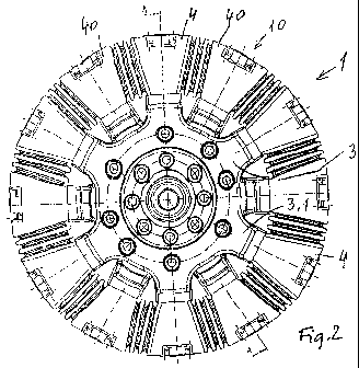
Fig. 2 shows an enlarged view of the coupling apparatus according to Fig. 1
with
a view on a face side;
Fig. 3 shows a view of the item of Fig. 2 according to the line of
intersection A-A;
Fig. 4 shows a spring element in a side view;
Fig. 5 shows the spring element according to Fig. 4 in a perspective view;
Fig. 6 shows a wedge-like carrier in a side view;
Fig. 7 shows the item of Fig. 6 in a top view;

CA 02787519 2012-07-19
4
The coupling apparatus shown in Fig. 1 comprises two disk-like couplings 1,
10.
They are arranged in a substantially similar or even identical manner. The
coupling
shown on the left in Fig. 1 is associated with the drive axle shaft (not
shown), and
the coupling shown on the right in the drawing is associated with the
transmission
output shaft, which is also not shown. The coupling apparatus according to
Fig. 1
assumes the function of a universal-joint shaft. A torque can be transmitted
thereby from the drive axle shaft onto the transmission output shaft which is
not
in alignment with the same.
Fig. 3 shows a hollow cardan shaft 2 which connects the two couplings 1 and 10
with each other.
Coupling 1 carries a serration 1.1 for transmitting torque from the drive axle
shaft
to the coupling 1. Coupling 10 carries serration 10.1 for transmitting torque
from
the coupling 10 to the transmission output shaft.
The configuration of the couplings shall be described in closer detail by
reference
to coupling 1. Coupling 1 comprises a star-shaped base body 3. It comprises
six
projections 3.1 which extend radially to the outside. Every projection carries
a very
decisive component, which is a carrier 4. The carrier 4 is wedge-shaped (see
Fig.
2). It tapers towards the rotational axis 5 of the apparatus.
Every carrier 4 is fixed to a projection 3.1 of the base body 3 by means of
screws
6. A straight pin 7 for positioning the carrier 4 is disposed between the two
screws
6, 6.
Fig. 2 shows that the two couplings 1, 10 are arranged in a substantially
similar
way. A wedge-shaped carrier 4 of the coupling 1 is disposed between two
adjacent wedge-shaped carriers 40, 40 of the coupling 10.

CA 02787519 2012-07-19
A packet of spring plates 8 and support plates 9 is fastened to the two wedge
surfaces of each carrier 4, 40. They are arranged in an alternating fashion.
The
spring plates are respectively vulcanized at first onto the respective wedge
surface
of the carrier 4, and thereafter onto the respective surface of the following
5 support plate 9. The support plates 9 can be made of sheet steel. It is also
possible to produce the support plates from another material.
The apparatus according to Figs. 1 to 3 is provided for the drive of rail
vehicles.
The coupling apparatus is used for compensating torsional vibrations between
the
drive axle and the pivoted bogey. The coupling apparatus will be installed in
the
pivoted bogey. The components in accordance with the invention compensate the
spring excursion of the primary spring in a cardanic fashion. The rubber
layers in
the spring units will be displaced in the axial direction in this process.
The packet of spring plates and support plates as shown in Fig. 4 on the right
is
non-tensioned, whereas the packet on the left is tensioned (also see Fig. 5).
Fig. 5 shows three mutually aligned boreholes, which is a middle borehole for
the
aforementioned straight pin 7 which is used as a locating pin, and the two
adjacent boreholes for one respective fastening screw 6.
Fig. 5 further shows a guide strip 20. It is provided in the spring units of
the one
coupling at its respective two ends, i.e. on the two outer support plates 9.
Two
grooves 21 are provided instead in the spring units of the other coupling (see
Fig.
7). The guide strips 20 of the one spring unit of the one coupling engage into
the
grooves 21 of the spring unit of the other coupling and are used for axial
securing,
which means for preventing an axial displacement of the spring units.

CA 02787519 2012-07-19
6
The spring plates 8 must be pretensioned in the mounted state so as to avoid
from being lifted off as a result of the drive torque. The pretensioning will
be
achieved automatically by mounting the wedge-shaped carriers.
Mounting can be pursued in two different ways:
The spring packets formed by the spring plates 8 and the support plates 9 can
be
inserted into the intermediate space between two mutually adjacent projections
3.1, 3.1. The wedge-shaped carrier 4 can then be inserted between the spring
packets and be tightened.
Alternatively, the spring unit consisting of the carrier 4 and the spring
plates 8 and
the support plates 9 can be joined in advance into a single unit and can then
be
inserted, followed by screwing the relevant carrier 4 to the projection 3.
The straight pin 7 is guided through the wedge-shaped carrier 4 and introduced
into the respective projection 3.1. It ensures the position of the components.
Brackets can additionally be provided which are fixed to the carriers 4 by
means of
screws and which reach beyond the spring packets consisting of the spring
plates
8 and the support plates 9. It is thereby ensured that the spring packets will
not
slide radially to the outside during operation.
The production of the coupling in accordance with the invention is very
simple.
The relevant parts of the spring unit, especially the wedge-shaped carriers 4,
can
be made of aluminum in order to reduce the weight of coupling.
The following sequence of mounting the elastic coupling in accordance with the
invention is advantageous:
- The straight pin 7 is inserted into the carrier 4 at first.

CA 02787519 2012-07-19
7
The unit consisting of the carrier 4, the spring plates 8 and the support
plates 9 will then be mounted on the base body 3.
It is ensured in this manner that each one of the guide strips 20 will be
disposed
in its correct position and will engage smoothly in the associated groove 21.
If
mounting is performed in reverse order, the guide strips 20 would need to be
readjusted during mounting.
It is understood that pin 7 need not necessarily be cylindrical, but can have
any
other cross section.
The aforementioned method can obviously also be applied in a coupling
apparatus
according to the claims 6 or 7. The coupling can also apply the component of a
coupling apparatus according to one of the claims 6 to 7.

CA 02787519 2012-07-19
8
List of reference numerals
1 Coupling
1.1 Serration
2 Hollow shaft
3 Base body
3.1 Projection
4 Wedge-shaped carrier
5 Rotational axis
6 Screws
7 Straight pin
8 Spring plates
9 Support plates
10 Coupling
10.1 Serration
Guide strip
21 Groove
40 Wedge-shaped carrier

Representative Drawing
A single figure which represents the drawing illustrating the invention.
Administrative Status

2024-08-01:As part of the Next Generation Patents (NGP) transition, the Canadian Patents Database (CPD) now contains a more detailed Event History, which replicates the Event Log of our new back-office solution.

Please note that "Inactive:" events refers to events no longer in use in our new back-office solution.

For a clearer understanding of the status of the application/patent presented on this page, the site Disclaimer , as well as the definitions for Patent , Event History , Maintenance Fee  and Payment History  should be consulted.

Event History

Description Date
Revocation of Agent Requirements Determined Compliant 2020-09-01
Revocation of Agent Requirements Determined Compliant 2018-04-27
Inactive: Adhoc Request Documented 2018-01-30
Application Not Reinstated by Deadline 2015-11-06
Time Limit for Reversal Expired 2015-11-06
Deemed Abandoned - Failure to Respond to Maintenance Fee Notice 2014-11-06
Inactive: Cover page published 2012-10-10
Inactive: IPRP received 2012-09-18
Inactive: Notice - National entry - No RFE 2012-09-07
Inactive: IPC assigned 2012-09-06
Inactive: First IPC assigned 2012-09-06
Application Received - PCT 2012-09-06
National Entry Requirements Determined Compliant 2012-07-19
Application Published (Open to Public Inspection) 2011-07-28

Abandonment History

Abandonment Date Reason Reinstatement Date
2014-11-06

Maintenance Fee

The last payment was received on 2013-10-25

Note : If the full payment has not been received on or before the date indicated, a further fee may be required which may be one of the following

  • the reinstatement fee;
  • the late payment fee; or
  • additional fee to reverse deemed expiry.

Please refer to the CIPO Patent Fees web page to see all current fee amounts.

Fee History

Fee Type Anniversary Year Due Date Paid Date
Basic national fee - standard 2012-07-19
MF (application, 2nd anniv.) - standard 02 2012-11-06 2012-10-25
MF (application, 3rd anniv.) - standard 03 2013-11-06 2013-10-25
Owners on Record

Note: Records showing the ownership history in alphabetical order.

Current Owners on Record
VOITH PATENT GMBH
Past Owners on Record
WALTER MISTLBAUER
Past Owners that do not appear in the "Owners on Record" listing will appear in other documentation within the application.
Documents

To view selected files, please enter reCAPTCHA code :


To view images, click a link in the Document Description column. To download the documents, select one or more checkboxes in the first column and then click the "Download Selected in PDF format (Zip Archive)" or the "Download Selected as Single PDF" button.

List of published and non-published patent-specific documents on the CPD .

If you have any difficulty accessing content, you can call the Client Service Centre at 1-866-997-1936 or send them an e-mail at CIPO Client Service Centre.


Document
Description 
Date
(yyyy-mm-dd) 
Number of pages   Size of Image (KB) 
Claims 2012-07-19 3 70
Description 2012-07-19 8 231
Drawings 2012-07-19 2 88
Abstract 2012-07-19 1 102
Representative drawing 2012-10-10 1 39
Cover Page 2012-10-10 2 77
Reminder of maintenance fee due 2012-09-10 1 113
Notice of National Entry 2012-09-07 1 194
Courtesy - Abandonment Letter (Maintenance Fee) 2015-01-02 1 171
Reminder - Request for Examination 2015-07-07 1 124
PCT 2012-07-19 31 1,199
PCT 2012-07-20 7 245