Note: Descriptions are shown in the official language in which they were submitted.
CA 02788031 2012-08-27
MULTI-FUNCTION REAR SEAT STRUCTURE MECHANISM
CROSS-REFERENCE TO RELATED APPLICATION
[0001] This application claims priority to and all the benefits of U.S.
Provisional
Application Serial No. 61/528,835, filed August 30, 2011.
BACKGROUND OF THE INVENTION
1. Field of the Invention
[0002] The present invention relates to a seat assembly for an automotive
vehicle.
More particularly, the present invention relates to a rear seat assembly for a
pick-up truck
that is selectively movable between a design seating position, a plurality of
slouch positions,
a fold and kneel position, and a stadium position.
2. Description of Related Art
[0003] It is common for pick-up trucks to have passenger cabins with one or
more
rear seat assemblies. The rear seat assemblies are positioned between a row of
front seat
assemblies and a rear wall of the cabin. In order to provide satisfactory
passenger comfort
for occupants using the rear seat assemblies, the rear seat assemblies may be
positioned in a
forward position relative to the rear wall of the cabin to provide sufficient
space to allow for
a reclining seat back of the rear seat assemblies. However, positioning the
rear seat
assemblies in the forward position decreases the amount of storage space
available behind
the row of front seat assemblies. Therefore, while it is desirable to provide
a reclining seat
back for the rear seat assemblies, it is also desirable to position the rear
seat assemblies
adjacent to the rear wall of the cabin to maximize storage space.
[0004] Several manufacturers provide rear seat assemblies adjacent to the rear
wall of
the cabin that allow the rear seat assemblies to "slouch", which effectively
reclines the seat
back. These rear seat assemblies are also operable to one or more stowed
positions to
increase the storage space available behind the row of front seat assemblies.
709292 CA
CA 02788031 2012-08-27
[00051 There remains, however, a need for a rear seat assembly for a cabin of
a pick-
up truck that simply and effectively maximizes passenger comfort and cabin
storage space.
SUMMARY
[0006] According to one embodiment of the invention, a seat assembly for a
motor
vehicle includes a seat cushion and a seat back. A front leg extends between a
first end
pivotally coupled to the seat cushion and a second end releasably coupled to a
floor of the
vehicle. A rear leg extends between a first end pivotally coupled to the seat
cushion and a
second end pivotally coupled to the floor. The seat back is pivotally coupled
to a recliner
bracket. The seat cushion is selectively locked to the recliner bracket to
prevent pivotal
movement of the seat cushion relative to the recliner bracket. A disc recliner
operatively
couples the recliner bracket and the second end of the rear leg. The disc
recliner is
selectively operable between a locked condition, preventing pivotal movement
of the rear leg
relative to the recliner bracket, and an unlocked condition, allowing pivotal
movement of the
rear leg relative to the recliner bracket. The disc recliner is actuated to
the unlocked
condition to allow the front and rear legs to pivot forwardly away from a back
wall of the
vehicle, thereby reclining the seat back as the seat assembly moves from a
design seating
position to a slouch position. The seat back is pivoted towards the seat
cushion and the
recliner is actuated to the unlocked condition to allow the front and rear
legs to pivot
forwardly, thereby lowering the seat assembly towards the floor as the seat
assembly moves
from the design seating position to a fold and kneel position. The front leg
is released from
the floor and the seat cushion is unlocked relative to the recliner bracket to
allow the seat
cushion to pivot towards the seat back as the seat assembly moves from the
design seating
position to a stadium position.
BRIEF DESCRIPTION OF THE DRAWINGS
[0007] Other advantages of the present invention will be readily appreciated
as the
same becomes better understood by reference to the following detailed
description when
considered in connection with the accompanying drawings, wherein:
2
709292 CA
CA 02788031 2012-08-27
[0008] Figure 1 is a side view of a pick-up truck including a rear seat
assembly
according to one embodiment of the invention;
100091 Figure 2 is a side view of the rear seat assembly in a design seating
position;
[0010] Figure 3 is a side view of the rear seat assembly in a slouch position;
100111 Figure 4 is a side view of the rear seat assembly in a fold and kneel
position:
10012] Figure 5 is a side view of the rear seat assembly in a stadium
position;
10013] Figure 6 is a perspective view of the rear seat assembly in the design
seating
position;
100141 Figure 7 is a fragmentary, partial cross-sectional side view of the
rear seat
assembly;
[0015] Figure 8 is a fragmentary, partially exploded perspective view of the
rear seat
assembly;
[00161 Figure 9 is a side view of a latch pin engaged with a wall bracket;
[0017] Figure 10 is a top view of the latch pin engaged with the wall bracket;
10018] Figure 11 is a top view of the latch pin disengaged from the wall
bracket;
[0019] Figure 12 is a fragmentary, side view of the rear seat assembly
illustrating a
cushion latch mechanism; and
10020] Figure 13 is a fragmentary, inner perspective view of the rear seat
assembly
illustrating the cushion latch mechanism.
DETAILED DESCRIPTION OF THE EMBODIMENTS
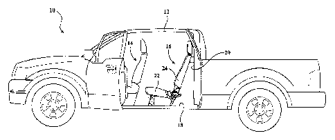
[00211 Referring to the Figures, a pick-up truck 10 includes a passenger cabin
12
having a front seat assembly, generally shown at 14, and a rear seat assembly,
generally
3
709292 CA
CA 02788031 2012-08-27
shown at 16. Both the front seat assembly 14 and the rear seat assembly 16 are
mounted on a
floor 18 of the passenger cabin 12 and the rear seat assembly 16 is positioned
adjacent a back
wall 20 of the passenger cabin 12. While the rear seat assembly 16 is shown in
the pick-up
truck 10, it is appreciated that the rear seat assembly 16 may be used in a
rear portion of any
vehicle where space is at a premium and occupant comfort is desired.
10022] The rear seat assembly 16, or seat assembly, as referred to herein,
includes a
seat cushion 22 and a seat back 24. As is well known in the art, the seat
cushion 22 includes
a foam pad covered in upholstery and supported by a seat cushion frame 26.
Similarly, the
seat back 24 includes a foam pad covered in upholstery and supported by a seat
back frame
28. The seat cushion 22 and seat back 24 are operatively coupled together as
described in
detail below.
100231 Referring to Figure 6, the seat cushion frame 26 extends between a
forward
end 30 and a rearward end 32 and is supported above the floor 18 of the
passenger cabin 12
by four pivotable legs. A pair of front legs 34 extends between a first end 36
pivotally
coupled to the forward end 30 of the seat cushion frame 26 at pivot 38 and a
second end 40
releasably coupled to the floor 18. More specifically, the second end 40 of
the front legs 34
includes a floor latch 42 that engages a floor striker 44 mounted on the floor
18 to secure the
front legs 34 to the floor 18, best seen in Figure 7. The floor latches 42 are
selectively
operable to disengage from the floor strikers 44 to release the front legs 34
from the floor 18
in response to actuating a stadium release handle 46. The stadium release
handle 46 is
operatively coupled to each of the floor latches 42 with a Bowden-type cable
48. In one
embodiment, the stadium release handle 46 is mounted generally at the forward
end 30 of the
seat cushion frame 26. It is appreciated, however, that the stadium release
handle 46 may be
mounted anywhere on the seat assembly 16 without varying from the scope of the
invention.
A cross-tube 50 extends between and couples the front legs 34 together to
ensure the front
legs 34 move in unison as described below.
[0024] A pair of rear legs 52 extends between a first end 54 pivotally coupled
to the
rearward end 32 of the seat cushion frame 26 and a second end 56 pivotally
coupled to an
attachment bracket 58 mounted on the floor 18. More specifically, an inner
side 60 of the
4
709292 CA
CA 02788031 2012-08-27
first end 54 of the rear legs 52 includes a bushing attachment bracket 62
fixedly secured
thereto and a bushing 64 is fixedly secured to the bushing attachment bracket
62, as shown in
Figure 8. The rearward end 32 of the seat cushion frame 26 includes a pivot
bracket 66 that
is fixedly thereto. The pivot bracket 66 is pivotally coupled to the bushing
64, thereby
defining a cushion pivot axis 68. The seat cushion 22 pivots about the cushion
pivot axis 68
as described below. The second end 56 of the rear legs 52 is pivotally coupled
to the
attachment bracket 58 at pivot 70. The seat assembly 16 may include a leg
biasing spring
(not shown) to urge the rear legs 52 about the pivot 70 in a rearward
direction, towards the
back wall 20, which is clockwise when viewed from Figure 2. A cross-tube 72
extends
between and couples the rear legs 52 together to ensure the rear legs 52 move
in unison as
described below.
10025] The seat back frame 28 extends between an upper end 74 and a lower end
76.
The upper end 74 of the seat back frame 28 may include a head restraint 78
operatively
coupled thereto that is movable between an upright use position and a folded
stowed
position. The upper end 74 of the seat back frame 28 is slidably and
releasably coupled to
the back wall 20 of the passenger cabin 12. More specifically, each side of
the upper end 74
of the seat back frame 28 includes a latch pin 80 that is received in a wall
bracket 82
mounted on the back wall 20 to secure the upper end 74 of the seat back frame
28 to the back
wall 20. The latch pins 80 include a distal end having a chamfered edge 84.
When viewed
from above, as shown in Figures 10 and 11, the wall brackets 82 include a
stepped profile
having an outer segment 86 and an inner segment 88. The outer segment 86 is
farther from
the seat back frame 28 relative to the inner segment 88. The wall brackets 82
also include an
elongated vertical slot 90 that is located at a step between the outer segment
86 and the inner
segment 88, as shown in Figure 9. The slots 90 extend generally vertically
between an upper
end 91 and a lower end 92. The latch pins 80 are spring biased to an extended
position
protruding from the seat back frame 28 in a lateral direction. In the extended
position, the
latch pins 80 are adapted to engage the slots 90 in the wall brackets 82. The
latch pins 80 are
selectively retractable to disengage from the slots 90 in the wall brackets 82
to release the
upper end 74 of the seat back frame 28 from the back wall 20 in response to
actuating a fold
5
709292 CA
CA 02788031 2012-08-27
flat release handle 93. The fold flat release handle 93 is operatively coupled
to each of the
latch pins 80 with a Bowden-type cable or linkage (not shown).
[00261 The lower end 76 of the seat back frame 28 is pivotally coupled to a
pair of
recliner brackets 94. The recliner brackets 94 extend between a first end 96
and a second end
98. The lower end 76 of the seat back frame 28 is pivotally coupled to the
first end 96 of the
recliner brackets 94 at pivot 100. The seat assembly 16 may include a seat
back biasing
spring (not shown) to bias the seat back 24 about the pivot 100 in a forward
direction, away
from the back wall 20, which is counterclockwise when viewed from Figure 2.
The second
end 98 of the recliner brackets 94 is operatively coupled to an outer side 102
of the first end
54 of the rear legs 52. More specifically, a disc recliner 104, which is well
known in the art,
is coupled between the outer side 102 of the first end 54 of the rear legs 52
and the second
end 98 of the recliner brackets 94. The disc recliners 104 define a recliner
pivot axis 106 that
is coaxial with the cushion pivot axis 68. The disc recliners 104 are
selectively operable
between a locked condition, preventing pivotal movement of the rear legs 52
relative to the
recliner brackets 94 about the recliner pivot axis 106, and an unlocked
condition, allowing
pivotal movement of the rear legs 52 relative to the recliner brackets 94
about the recliner
pivot axis 106. The disc recliners 104 are normally biased to the locked
condition. The disc
recliners 104 are selectively operable to the unlocked condition in response
to actuating a
recliner release handle (not shown) that is typically mounted on a shaft 110
of one of the disc
recliners 104, as is well known in the art. A recliner cable (not shown)
extends between the
disc recliners 104 to synchronize actuation of the disc recliners 104 between
the locked and
unlocked conditions. The recliner brackets 94 include a torsion bar mount 112
that protrudes
in the rearward direction away from the rearward end 32 of the seat cushion
frame 26, as
shown in Figure 7. A torsion support tube 114 extends between the torsion bar
mounts 112
and couples the recliner brackets 94 together.
[00271 The seat cushion frame 26 is pivotally locked relative to the recliner
brackets
94 by a cushion latch mechanism 116. The cushion latch mechanism 116 includes
a cushion
latch 118 and a receiver bracket 120. The cushion latch 118 is pivotally
coupled to a side
member 122 of the seat cushion frame 26 at pivot 124 and the receiver bracket
120 is fixedly
6
709292 CA
CA 02788031 2012-08-27
secured to one of the recliner brackets 94. The cushion latch 118 is generally
L-shaped and
includes one end having a hook 126 that engages a recess 128 in the receiver
bracket 120 to
pivotally lock the seat cushion frame 26 relative to the recliner brackets 94.
The cushion
latch 118 includes a post 130 extending in the lateral direction from an end
of the cushion
latch 118 opposite the hook 126. The post 130 extends through a slot 132 in
the side member
122 of the seat cushion frame 26. The cushion latch 118 is selectively
operable to disengage
the hook 126 from the recess 128 in the receiver bracket 120 in response to
actuating the
stadium release handle 46. The stadium release handle 46 is operatively
coupled to the
cushion latch 118 with a Bowden-type cable 134 extending between the post 130
and the
stadium release handle 46. When the hook 126 is disengaged from the recess
128, the seat
cushion frame 26 is pivotable about the cushion pivot axis 68 relative to the
recliner brackets
94. A return spring 136 is connected between the seat cushion frame 26 and the
post 130 to
bias the cushion latch 118 in a direction to engage the hook 126 with the
recess 128 in the
receiver bracket 120.
[00281 A cable 138 is routed between the torsion support tube 114 and one of
the
front legs 34 to pivot the front legs 34 from a support position to a
retracted position in
response to pivoting the seat cushion 22 about the cushion pivot axis 68
towards the seat
back 24. In the retracted position, the front legs 34 are disposed adjacent to
an underside of
the seat cushion 22. The front legs 34 may be biased towards the support
position. More
specifically, a first end 140 of the cable 138 is coupled to one of the front
legs 34 between the
first end 36 and the second end 40. A second end 142 of the cable 138 is
coupled to the
torsion support tube 114 by an extension element, such as a cable spring 144.
Between the
first end 140 and the second end 142, the cable 138 is routed around a cable
guide 146 and
extends through a cable conduit 148 that is secured to the side member 122 of
the seat
cushion frame 26. The cable guide 146 is mounted on the cross-tube 72
extending between
the rear legs 52. Thus, as the seat cushion 22 pivots about the cushion pivot
axis 68 towards
the seat back 24, an effective length of the cable 138 is reduced due to the
fixed position of
the cable guide 146 relative to the cushion pivot axis 68, thereby causing the
front legs 34 to
pivot about the pivot 38 towards the retracted position. Once the front legs
34 reach the
retracted position, the cable spring 144 allows the seat cushion 22 to
continue to rotate about
7
709292 CA
CA 02788031 2012-08-27
the cushion pivot axis 68 toward the seat back 24 without unduly stressing the
cable 138. It
is appreciated that the cable spring 144 will also protect against abusive
loading of the cable
138. For example, if an occupant attempts to pivot the front legs 34 out of
the retracted
position while the seat cushion 22 is adjacent to the seat back 24, the cable
spring 144 will
extend to protect the cable 138. In an alternative embodiment, the cable 138
may be replaced
with a connecting link having a lost motion slot that operatively connects the
front legs 34
and the rear legs 52 to pivot the front legs 34 to the retracted position in
response to pivoting
the seat cushion 22 about the cushion pivot axis 68 towards the seat back 24.
[0029] In operation, the seat assembly 16 is shown in Figure 2 in a design
seating
position, wherein the seat cushion 22 is supported generally horizontal in a
raised position
above the floor 18 and the seat back 24 is supported generally vertical in an
upright position.
The floor latches 42 are engaged with the floor strikers 44 to secure the
second end 40 of the
front legs 34 to the floor 18. The latch pins 80 are engaged with the slots 90
in the wall
brackets 82 such that the upper end 74 of the seat back frame 28 is secured to
the back wall
20 of the passenger cabin 12. In one embodiment, the latch pins 80 are
disposed at the upper
end 91 of the slots 90 when the seat assembly 16 is in the design seating
position. The disc
recliners 104 are in the locked condition to prevent pivotal movement of the
rear legs 52
relative to the recliner brackets 94 about the recliner pivot axis 106. In
addition, the hook
126 on the cushion latch 118 is engaged with the recess 128 in the receiver
bracket 120 to
prevent pivotal movement of the seat cushion 22 about the cushion pivot axis
68.
[0030] In order to move the seat assembly 16 from the design seating position
to one
of a plurality of slouch positions, one of which is shown in Figure 3. the
recliner release
handle is lifted and the disc recliners 104 actuate to the unlocked condition
to allow pivotal
movement of the rear legs 52 relative to the recliner brackets 94 about the
recliner pivot axis
106. With the disc recliners 104 in the unlocked condition, the front legs 34
and the rear legs
52 pivot in the forward direction, away from the back wall 20
(counterclockwise when
viewed from Figures 2 and 3), in response to an input force from a seat
occupant. More
specifically, the front legs 34 pivot about the floor strikers 44 and the rear
legs 52 pivot about
the pivot 70, thereby moving the seat cushion 22 forwardly. Since the upper
end 74 of the
8
709292 CA
CA 02788031 2012-08-27
seat back frame 28 is coupled to the back wall 20, as the seat cushion 22
moves forwardly,
the pivot 100 between the lower end 76 of the seat back frame 28 and the first
end 96 of the
recliner brackets 94 allows the seat back 24 to effectively recline. The latch
pins 80 move
downward within the slots 90 in the wall brackets 82 as the seat back 24
reclines. Once the
seat assembly 16 is in the desired slouch position, the recliner release
handle is released to
allow the disc recliners 104 to return to the locked condition, which thereby
prevents any
further movement of the seat assembly 16. The plurality of slouch positions is
limited by the
lower end 92 of the slots 90 in the wall brackets 82. For example, as the seat
back 24
reclines the latch pins 80 will reach the lower end 92 of the slots 90,
thereby preventing the
seat back 24 from reclining any further and thereby limiting the plurality of
slouch positions.
10031] To return the seat assembly 16 from the slouch position to the design
seating
position, the recliner release handle is again lifted and the disc recliners
104 actuate to the
unlocked condition. With the disc recliners 104 in the unlocked condition, the
front legs 34
and the rear legs 52 pivot in the rearward direction, towards the back wall 20
(clockwise
when viewed from Figure 3), in response to another input force from the seat
occupant. The
leg biasing spring will also urge the rear legs 52 about the pivot 70 in the
rearward direction.
More specifically, the front legs 34 pivot about the floor strikers 44 and the
rear legs 52 pivot
about the pivot 70, thereby moving the seat cushion 22 rearwardly. Since the
upper end 74
of the seat back frame 28 is coupled to the back wall 20, as the seat cushion
22 moves
rearwardly, the pivot 100 between the lower end 76 of the seat back frame 28
and the first
end 96 of the recliner brackets 94 allows the seat back 24 to return to the
upright position.
The latch pins 80 move upward within the slots 90 in the wall brackets 82 as
the seat back 24
returns to the upright position. Once the seat assembly 16 is in the design
seating position,
the recliner release handle is released to allow the disc recliners 104 to
return to the locked
condition, which thereby prevents any further movement of the seat assembly
16.
100321 In order to move the seat assembly 16 from the design seating position
to a
fold and kneel position, shown in Figure 4. the fold flat release handle 93 is
lifted and the
latch pins 80 retract from the slots in the wall brackets 82, thereby
releasing the upper end 74
of the seat back frame 28 from the back wall 20. The seat back 24 then pivots
forwardly
9
709292 CA
CA 02788031 2012-08-27
about the pivot 100 toward the seat cushion 22 in response to the seat back
biasing spring.
Once the seat back 24 reaches a predetermined position, a cable (not shown)
operatively
coupled between the seat back 24 and the disc recliners 104 actuates the disc
recliners 104 to
the unlocked condition. With the disc recliners 104 in the unlocked condition,
the weight of
the seat assembly 16 causes the front legs 34 and the rear legs 52 to pivot in
the forward
direction, away from the back wall 20 (counterclockwise when viewed from
Figures 2 and
4). More specifically, the front legs 34 pivot about the floor strikers 44 and
the rear legs 52
pivot about the pivot 70, thereby moving the seat cushion 22 forwardly and
downwardly.
The seat back 24 continues to pivot forwardly until the seat back 24 is
adjacent to the seat
cushion 22 and the seat cushion 22 continues to move forwardly and downwardly
until the
seat cushion 22 is adjacent to the floor 18. Since the leg biasing spring
urges the rear legs 52
in the rearward direction (clockwise when viewed from the Figures), it is
appreciated that the
leg biasing spring will help counteract the weight of the seat assembly 16 as
the seat
assembly 16 is lowered towards the floor 18. It is further appreciated that as
the seat back 24
is folded against the seat cushion 22, the head restraint 78 may automatically
actuate from the
upright use position to the folded stowed position.
[00331 To return the seat assembly 16 from the fold and kneel position to the
design
seating position, a portion of the seat assembly 16 is lifted to move the seat
cushion 22
upwardly and rearwardly to the raised position. As the seat cushion 22 moves
upwardly and
rearwardly, the front legs 34 and the rear legs 52 pivot in the rearward
direction, towards the
back wall 20 (clockwise when viewed from Figure 4). More specifically, the
front legs 34
pivot about the floor strikers 44 and the rear legs 52 pivot about the pivot
70. It is
appreciated that movement of the seat cushion 22 to the raised position is
assisted by the leg
biasing spring urging the rear legs 52 in the rearward direction. Once the
seat cushion 22
reaches the raised position, the disc recliners 104 return to the locked
condition. It is
contemplated that the disc recliners 104 may include a memory feature
corresponding to the
raised position such that the disc recliners 104 automatically return to the
locked condition
when the seat cushion 22 reaches the raised position. With the disc recliners
104 in the
locked condition, the seat back 24 is then pivoted rearwardly about the pivot
100 towards the
back wall 20. As the seat back 24 pivots towards the back wall 20, the
chamfered edge 84 of
709292 CA
CA 02788031 2012-08-27
the latch pins 80 contacts the outer segment 86 of the wall brackets 82, which
pushes the
latch pins 80 inwardly. The seat back 24 continues to pivot towards the back
wall 20 until
the latch pins 80 are aligned with the slots 90, thereby allowing the latch
pins 80 to return to
the extended position and engage the slots 90 in the wall brackets 82. With
the disc recliners
104 in the locked condition and the upper end 74 of the seat back frame 28
secured to the
back wall 20, any further movement of the seat assembly 16 is prevented. It is
contemplated
that if the seat assembly 16 is lifted by the seat back 24, the spring force
of the seat back
biasing spring is such that the seat cushion 22 will return to the raised
position and the disc
recliners 104 will return to the locked condition before the seat back 24
begins to pivot about
the pivot 100. In one alternative, an interlock may be used such that the seat
back 24 will not
pivot about the pivot 100 until the seat cushion 22 reaches the raised
position and the disc
recliners 104 actuate to the locked condition.
[0034] In order to move the seat assembly 16 from the design seating position
to a
stadium position, shown in Figure 5, the stadium release handle 46 is lifted
and the cable 48
actuates the floor latches 42 to disengage from the floor strikers 44, thereby
releasing the
front legs 34 from the floor 18. As the stadium release handle 46 continues to
be lifted, the
hook 126 of the cushion latch 118 disengages from the recess 128 in the
receiver bracket 120
to unlock the seat cushion frame 26 from the recliner brackets 94. With the
front legs 34
released from the floor 18 and the seat cushion frame 26 unlocked from the
recliner brackets
94, the seat cushion 22 is free to pivot about the cushion pivot axis 68
towards the seat back
24. It is contemplated that a seat cushion biasing spring (not shown) may urge
the seat
cushion 22 to pivot rearwardly about the cushion pivot axis 68 without varying
from the
scope of the invention. As the seat cushion 22 pivots rearwardly about the
cushion pivot axis
68, the effective length of the cable 138 is reduced, thereby causing the
front legs 34 to pivot
about the pivot 38 towards the retracted position. At the same time, the rear
legs 52 pivot
about the pivot 70 in the rearward direction, towards the back wall 20
(clockwise when
viewed from Figures 2 and 5), thereby moving the lower end 76 of the seat back
frame 28
towards the back wall 20. It is appreciated that pivotal movement of the rear
legs 52 in the
rearward direction is assisted by the leg biasing springs. As the lower end 76
of the seat back
frame 28 moves towards the back wall 20, the latch pins 80 move downward
within the slots
11
709292 CA
CA 02788031 2012-08-27
90 in the wall brackets 82. In one embodiment, the latch pins 80 are disposed
at the lower
end 92 of the slots 90 when the seat assembly 16 is in the stadium position.
10035] To return the seat assembly 16 from the stadium position to the design
seating
position, the seat cushion 22 is pivoted forwardly about the cushion pivot
axis 68 away from
the seat back 24. As the seat cushion 22 pivots forwardly about the cushion
pivot axis 68, the
effective length of the cable 138 is increased, thereby allowing the front
legs 34 to pivot
about the pivot 38 towards the support position. At the same time, the rear
legs 52 pivot
about the pivot 70 in the forward direction, away from the back wall 20
(counterclockwise
when viewed from Figure 5), thereby moving the lower end 76 of the seat back
frame 28
away from the back wall 20. As the lower end 76 of the seat back frame 28
moves away
from the back wall 20, the latch pins 80 move upward within the slots 90 in
the wall brackets
82. As the seat cushion 22 continues to pivot forwardly about the cushion
pivot axis 68, the
hook 126 of the cushion latch 118 engages the recess 128 in the receiver
bracket 120 to
pivotally lock the seat cushion frame 26 relative to the recliner brackets 94.
The rear legs 52
continue to pivot about the pivot 70 in the forward direction until the floor
latches 42 engage
with the floor strikers 44, thereby securing the front legs 34 to the floor
18.
100361 The invention has been described herein in an illustrative manner, and
it is to
be understood that the terminology used is intended to be in the nature of
words of
description rather than limitation. Many modifications and variations of the
present
invention are possible in light of the above teachings. It is, therefore, to
be understood that
within the scope of the appended claims, the invention may be practiced other
than as
specifically enumerated within the description.
12
709292 CA