Language selection

Search

Patent 2788160 Summary

Third-party information liability

Some of the information on this Web page has been provided by external sources. The Government of Canada is not responsible for the accuracy, reliability or currency of the information supplied by external sources. Users wishing to rely upon this information should consult directly with the source of the information. Content provided by external sources is not subject to official languages, privacy and accessibility requirements.

Claims and Abstract availability

Any discrepancies in the text and image of the Claims and Abstract are due to differing posting times. Text of the Claims and Abstract are posted:

  • At the time the application is open to public inspection;
  • At the time of issue of the patent (grant).
(12) Patent Application: (11) CA 2788160
(54) English Title: DECORATIVE MOLDING WITH FILM
(54) French Title: MOULAGE DECORATIF A COUCHE MINCE
Status: Dead
Bibliographic Data
(51) International Patent Classification (IPC):
  • B60R 13/02 (2006.01)
  • B60J 10/235 (2016.01)
  • B60J 10/265 (2016.01)
  • B60J 10/30 (2016.01)
  • B60J 10/02 (2006.01)
(72) Inventors :
  • ELLIS, PETER JOHN (United States of America)
  • KAWASE, HARUHISA (United States of America)
  • ZOHAR, AVI (Canada)
  • WARD, MALCOLM (Canada)
(73) Owners :
  • MAGNA INTERNATIONAL INC. (Canada)
(71) Applicants :
  • MAGNA INTERNATIONAL INC. (Canada)
(74) Agent: MILLMAN IP INC.
(74) Associate agent:
(45) Issued:
(86) PCT Filing Date: 2011-02-16
(87) Open to Public Inspection: 2011-08-25
Availability of licence: N/A
(25) Language of filing: English

Patent Cooperation Treaty (PCT): Yes
(86) PCT Filing Number: PCT/US2011/024964
(87) International Publication Number: WO2011/103109
(85) National Entry: 2012-07-24

(30) Application Priority Data:
Application No. Country/Territory Date
61/338,234 United States of America 2010-02-16

Abstracts

English Abstract

A molding for attachment to a flange portion includes a retention portion having first and second legs defining a channel for receiving the flange portion, and a support member coupled to the retention portion and movable relative thereto. The support member includes an outboard surface and an inboard surface. A film is disposed along the outboard surface of the support member, A clip is formed along and extends out from the first leg of the retention portion. The clip is engageable with the support member to lock the support member in place relative to the retention portion for positioning the film along the flange portion.


French Abstract

L'invention concerne un moulage à fixer à une partie rebord comprenant une partie de retenue dotée d'une première et d'une seconde patte définissant un canal destiné à recevoir ladite partie rebord, et un élément de support couplé à la partie de retenue et mobile par rapport à cette dernière. L'élément de support comprend une surface extérieure et une surface intérieure. Une couche mince est disposée sur la surface extérieure de l'élément de support. Une attache est formée le long de la première patte de la partie de retenue et s'étend vers l'extérieur à partir de cette dernière. L'attache vient en contact avec l'élément de support pour le verrouiller en place par rapport à l'élément de retenue afin de positionner la couche mince le long de la partie rebord.

Claims

Note: Claims are shown in the official language in which they were submitted.


What is claimed:

1. A molding for attachment to a flange portion, said molding comprising:

a retention portion having first and second legs defining a channel that is
adapted for
receiving the flange portion;

a support member coupled to said retention portion and movable relative
thereto, said
support member including an outboard surface and an inboard surface;

a film disposed along said outboard surface of said support member, and

a clip formed along and extending out from said first leg of said retention
portion, said
clip engageable with said support member to lock said support member in place
relative to
said retention portion to position said film in place along the flange
portion.

2. A molding as set forth in claim 1 including a connecting wall coupling said
first and
second legs together thereby defining said channel.

3. A molding as set forth in claim 2 including a shoulder portion extending
out from said
connecting wall away from said channel.

4. A molding as set forth in claim 3 wherein said support member extends
between a
first end coupled to said shoulder portion and a second end.

5. A molding as set forth in claim 1 including a locking member extending from
said
inboard surface of said support member, wherein said locking member is adapted
to receive
said clip to lock said support member in place relative to said retention
portion.

6. A molding as set forth in claim 5 wherein said locking member defines an
aperture
between a pair of inner walls for receiving said clip therein.

7. A molding as set forth in claim 6 wherein said clip includes a base
portion, a neck
having a thickness less than said base portion, and an arrowhead having a
thickness greater
than said base portion, wherein said arrowhead is disposed through said
aperture and said pair
of inner walls engage said neck to retain said arrowhead within said locking
member.

4


8. A molding as set forth in claim 3 including a concealing lip extending out
from said
shoulder portion to hide said retention portion when said molding is attached
to the flange
portion.

9. A molding as set forth in claim 1 including at least one holding finger
extending out
from said first leg toward said second leg, wherein said at least one holding
finger is adapted
for engaging the flange portion to securely maintain said molding along the
flange portion.
10. A molding as set forth in claim 9 including at least one protrusion
extending out from
said second leg toward said first leg, wherein said at least one protrusion is
adapted for
engaging the flange portion to securely maintain said molding along the flange
portion.

11. A molding as set forth in claim 1 including a carrier embedded within said
retention
portion to provide a rigid support therefor.

12. A molding as set forth in claim 1 wherein said retention portion is formed
from a
thermoplastic material having a durometer of about 67A.

13. A molding as set forth in claim 1 wherein said support member is formed
from a
plastic material having a durometer of approximately 40D.

14. A molding for attachment to a flange portion adjacent a window glass, said
molding
comprising:

a retention portion having first and second legs defining a channel that is
adapted for
receiving the flange portion;

at least one sealing lip extending out from said second leg away from said
first leg,
wherein said at least one sealing lip is adapted for sealing engagement with
the window glass;
a support member coupled to said retention portion and movable relative
thereto, said
support member including an outboard surface and an inboard surface;

a film disposed along said outboard surface of said support member; and

a clip formed along and extending out from said first leg of said retention
portion, said
clip engageable with said support member to lock said support member in place
relative to
said retention portion to position said film in place along the flange
portion.


15. A method of manufacturing a molding for attachment to a flange portion,
the molding
having a retention portion that is adapted for receiving the flange portion, a
support member
coupled to the retention portion and movable relative thereto, a film disposed
along an
outboard surface of the support member, and a clip extending out from the
retention portion
that is engageable with an inboard surface of the support member, the method
including the
steps of:

co-extruding the retention portion, the support member, and the film to form
the
molding with the support member in an open configuration;

applying the molding to the flange portion; and

pushing the clip into the locking member to retain the support member in a
closed
configuration.

6

Description

Note: Descriptions are shown in the official language in which they were submitted.


CA 02788160 2012-07-24
WO 2011/103109 PCT/US2011/024964
DECORATIVE MOLDING WITH FILM
CROSS-REFERENCE TO RELATED APPLICATION

[0001] This application claims priority to and all the benefits of United
States
Provisional Application No. 61/338,234, filed on February 16, 2010 and
entitled "Decorative
Molding With Film"

BACKGROUND OF THE INVENTION
1. Field of the Invention

[0001] The invention relates to moldings for motor vehicle doors, More
particularly,
the invention relates to a molding including a film disposed along a support
member.
SUMMARY

[0002] According to one aspect of the invention, a molding fhr attachment to a
flange
portion includes a retention portion having first and second legs defining a
channel for
receiving the flange portion, and a support member coupled to the retention
portion and
movable relative thereto. The support member includes an outboard surface and
an inboard
surface, A film is disposed along the outboard surface of the support member.
A clip is
formed along and extends out from the first leg of the retention portion, The
clip is
engageable with the support member to lock the support member in place
relative to the
retention portion to position the film along the flange portion.

BRIEF DESCRIPTION OF THE DRAWINGS

[0003] The invention will be readily appreciated as the same becomes better
understood by reference to the following detailed description when considered
in connection
with the accompanying drawings wherein:

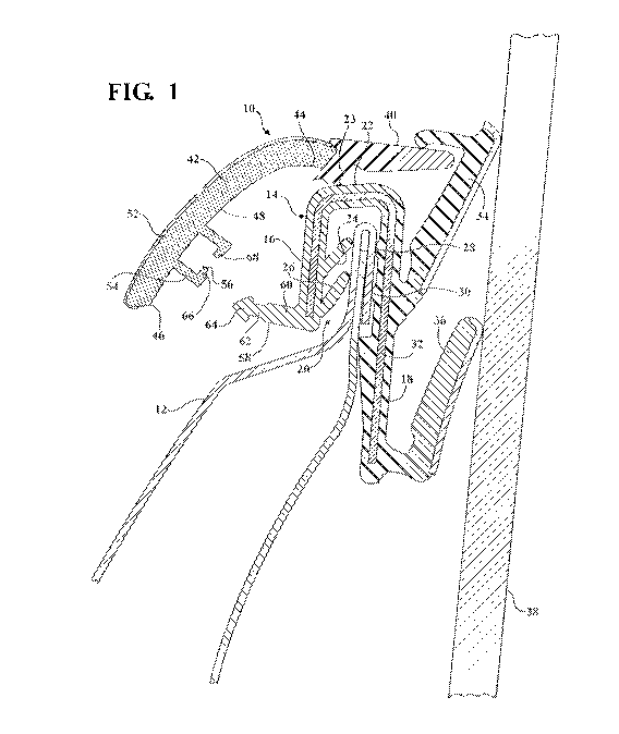
[0004] Figure l is a cross-sectional view of one embodiment of a molding; and

[0005] Figure 2 is a cross-sectional view of the molding including a clip
engaging a
support member.

DETAILED DESCRIPTION OF THE EMBODIMENTS
1


CA 02788160 2012-07-24
WO 2011/103109 PCT/US2011/024964
[0006] Referring to Figures 1 and 2, a molding, generally shown at 10, is
provided for
a motor vehicle component. In one embodiment, the molding 10 is an outer belt
molding that
is attached to a flange portion 1.2 of a motor vehicle door. It is, however,
appreciated that the
molding 10 may be any one of numerous moldings for positioning in any of a
variety of
locations along a motor vehicle.

[0007] The molding 10 includes a retention portion, generally indicated at 14,
having
first 16 and second 18 legs defining a channel 20 therehetween. A connecting
wall portion
22 couples the first leg 16 to the second leg 18. A shoulder portion 23 abuts
the connecting
wall portion 22 and extends out therefrom. The retention portion 14 is formed
from a
generally soft thermoplastic material. In one embodiment, the retention
portion 14 is formed
from a generally soft plastic material having a durometer of approximately
67A. A pair of
holding fingers 24, 26 extends out from the first leg 16, and first 28 and
second 30
protrusions extend out from the second leg 18, The pair of holding fingers 24,
26 and the
first 28 and second 30 protrusions retain the flange portion 1'2 on both sides
thereof to
securely maintain the molding 10 along the flange portion 12.

[0008] The molding 10 includes a carrier 32 embedded within the retention
portion 14
of the molding 10 to provide a rigid support therefor. In one embodiment, the
carrier 32 is
formed from a flexible metal material. A pair of sealing lips 34, 36 extends
out from the
second leg 18 for sealing engagement with a window glass 38. A concealing lip
40 extends
out from the shoulder portion 23 to hide the retention portion 14 of the
molding 10 from view
when the retention portion 14 is secured along the flange portion 12 of the
motor vehicle
door.

[0009] The molding 10 further includes a support member 42 extending between a
first end 44 abutting the shoulder portion 23 and a second end 46. The support
member 42
includes an inboard surface 48 and an outboard surface 50. The supportt member
42 is
formed from a hard plastic material. In one embodiment, the support member 42
has a
durorneter of approximately 401.

[0010] A film 52 is co-extruded with the molding 10 along the outboard surface
50 of
the support member 42. The hard support member 42 allows for the smooth
application of
the film 52 along the outboard surface 50 during the extrusion process. The
film 52-1 may be a


CA 02788160 2012-07-24
WO 2011/103109 PCT/US2011/024964
chrome fil-n, a high-gloss black film, or the like in order to provide the
molding 10 with an
aesthetically pleasing appearance.

[0011] The support member 42 also includes a locking member 54 formed along
and
extending out from the inboard surface 48. The locking member 54 defines an
aperture 56.
A clip 58 is formed along the first leg 1.6 of the retention portion 14 of the
molding 10. The
clip 58 includes a base portion 60, a neck 62, and an arrowhead 64. The clip
58 is received
within the aperture 56 to adjust the molding 10 from an open configuration,
shown in Figure
1, to a closed configuration, shown in Figure 2.

[Ã.1012] When the retention portion 14, the support member 42, and the film 52
are co-
extruded to form the molding 10, the molding 10 is initially in the open
configuration. When
the molding 10 is ready to be applied to a motor vehicle component, such as
the flange
portion 12 of the motor vehicle door, an operator will guide the clip 58 into
alignment with
the aperture 56 and then push the clip 58 into the locking member 54 until the
arrowhead 64
has moved completely through the aperture 56, as shown in Figure 2. At this
stage, the clip
64 is held within the locking member 54 by a pair of inner walls 66, 68 and
the molding 10 is
in the closed configuration.

[00131 The invention has been described in an illustrative manner. It is to be
understood that the terminology. which has been used, is intended to be in the
nature of
words of description rather than of limitation. Many modifications and
variations of the
invention are possible in light of the above teachings. Therefore, within the
scope of the
appended claims, the invention may be practiced other than as specifically
described.

3
3

Representative Drawing
A single figure which represents the drawing illustrating the invention.
Administrative Status

For a clearer understanding of the status of the application/patent presented on this page, the site Disclaimer , as well as the definitions for Patent , Administrative Status , Maintenance Fee  and Payment History  should be consulted.

Administrative Status

Title Date
Forecasted Issue Date Unavailable
(86) PCT Filing Date 2011-02-16
(87) PCT Publication Date 2011-08-25
(85) National Entry 2012-07-24
Dead Application 2016-02-16

Abandonment History

Abandonment Date Reason Reinstatement Date
2015-02-16 FAILURE TO PAY APPLICATION MAINTENANCE FEE

Payment History

Fee Type Anniversary Year Due Date Amount Paid Paid Date
Application Fee $400.00 2012-07-24
Maintenance Fee - Application - New Act 2 2013-02-18 $100.00 2012-12-17
Maintenance Fee - Application - New Act 3 2014-02-17 $100.00 2013-12-11
Owners on Record

Note: Records showing the ownership history in alphabetical order.

Current Owners on Record
MAGNA INTERNATIONAL INC.
Past Owners on Record
None
Past Owners that do not appear in the "Owners on Record" listing will appear in other documentation within the application.
Documents

To view selected files, please enter reCAPTCHA code :


To view images, click a link in the Document Description column. To download the documents, select one or more checkboxes in the first column and then click the "Download Selected in PDF format (Zip Archive)" or the "Download Selected as Single PDF" button.

List of published and non-published patent-specific documents on the CPD .

If you have any difficulty accessing content, you can call the Client Service Centre at 1-866-997-1936 or send them an e-mail at CIPO Client Service Centre.


Document
Description 
Date
(yyyy-mm-dd) 
Number of pages   Size of Image (KB) 
Abstract 2012-07-24 2 94
Claims 2012-07-24 3 150
Drawings 2012-07-24 2 167
Description 2012-07-24 3 190
Representative Drawing 2012-07-24 1 81
Cover Page 2012-10-11 2 61
Fees 2012-12-17 1 40
PCT 2012-07-24 2 94
Assignment 2012-07-24 6 191
Fees 2013-12-11 2 78