Note: Descriptions are shown in the official language in which they were submitted.
CA 02788428 2012-07-27
Our ref: 1153P001CA01 1
SPRAY NOZZLE UNIT
SPECIFICATION
The present invention proposes a spray nozzle unit for spraying heavily
dust-laden areas as well as potentially explosive areas in underground mining,
with a nozzle body that exhibits a nozzle opening for ejecting spray liquid.
PRIOR ART
Various methods are used for finely spraying liquids at a low water
consumption level.
1. Fine spray nozzles with very small bore diameters, e.g., 1 mm,
which are operated at high pressures ranging between 50 and 200 bar.
2. Two-component nozzles that use compressed air to finely atomize
the liquids.
The disadvantages include a potential jamming of nozzles on the one
hand, and the necessity for compressed air on the other, which are associated
with significant drawbacks, in particular in underground mining.
Known from DE 198 51 620 Al is a generic spray nozzle unit. Spray
nozzle units are used in particular for spraying potentially explosive areas
in
underground mining, and a plurality of spray nozzle units can be accommodated
on a nozzle receptacle of a spraying system, for example so as to spray the
cutting area of the selective cut heading machine with water underground. In
order to spray the cutting area as comprehensively as possible, it can be
provided that highly pressurized compressed air be added to the supplied water
to ensure that the water is effectively atomized, wherein the necessary water
consumption is reduced at the same time. However, the disadvantage to using
atomizing nozzles is that compressed air with high pressure values must be
provided to atomize the added water.
By contrast, spray nozzle units that do not need compressed air and
are operated at high water pressures lead to high water consumption. If the
diameter of the nozzle opening is diminished to reduce water consumption, a
high water pressure is necessary, which requires an intricate process to
prepare.
CA 02788428 2012-07-27
Our ref: 1153P001CA01 2
Given the harsh conditions under which such spray nozzle units are
used underground, in particular in direct proximity to the cutting area of a
selective cut heading machine, the spray nozzle unit must be furnished with an
appropriately robust design. Contaminants can penetrate into the nozzle
opening and end up jamming the spray nozzle unit, so that the cutting area of
a
selective cut heading machine might no longer be reliably sprayed. The machine
operator is basically unable to see the area in which the spray nozzle units
are
arranged in a nozzle receptacle of a spraying system. This makes it difficult
to
oversee the process of monitoring a spraying system to verify smooth
operation. Therefore, a nozzle unit having an especially robust design is
desirable.
AIM OF THE INVENTION
As a consequence, the aim of the present invention is to provide a
spray nozzle unit that overcomes the disadvantages to the prior art described
above, and enables low water consumption. Further, the aim of the present
invention is to provide a spray nozzle unit having a robust design. Finally,
the
aim of the present invention is to provide a spray nozzle unit with a low
water
consumption that enables compressed air-free operation, and is suitable for
use
in ultra high speed fire suppression systems at response times of below 50
milliseconds.
This aim is achieved based on a spray nozzle unit according to the
preamble to claim 1 in conjunction with its characterizing features. Practical
further developments of the invention are indicated in the dependent claims.
SUMMARY OF THE INVENTION
The invention encompasses the technical instruction that the nozzle
body incorporates a closing means that closes the nozzle opening with the
spray
nozzle unit in an unpressurized state.
The advantage achieved by arranging a closing means in the nozzle
body is that the nozzle opening can then be closed by the closing means when
the spray nozzle unit is not in operation, i.e., the spray nozzle unit is not
pressurized, and thus at zero pressure. No contaminants can get into the
nozzle
CA 02788428 2012-07-27
Our ref: 1153P001CA01 3
opening with the spray nozzle unit operational, since the exiting spray
liquid, in
particular water, prevents contaminants from penetrating into the nozzle
opening. If the spray nozzle unit is not operational, the closing means
according
to the invention prevents contaminants from entering the nozzle opening. As a
result, contaminants are prevented from penetrating into the nozzle opening,
regardless of the operating state of the spray nozzle unit. Arranging the
closing
means in the nozzle body itself protects the closing means against mechanical
influences, and the nozzle body of the spray nozzle unit can be given the
conventional outside design.
It is especially advantageous that the closing means be designed as a
clamping piston, which preferably is reciprocatingly incorporated in the
nozzle
body along a central axis of the nozzle body. The nozzle body can essentially
have a rotationally symmetrical configuration, basically giving it roughly
cylindrical shape. The rotational axis of the cylindrical nozzle body forms
the
central axis, wherein the clamping piston is also rotationally symmetrical. As
a
consequence, the clamping piston can be guided back and forth between a
closed position and open position along the central axis, wherein the clamping
piston closes the nozzle opening in the closed position, and releases it in
the
open position.
It is especially advantageous that the closing means be able to
reciprocate between a closed position and open position along the central axis
by pressurizing the spray nozzle unit with spray liquid. Pressurization with
the
spray liquid takes place in such a way that the closing means can be moved
from
the open position to the closed position. Once pressurization has ended, the
closing means moves back into the closed position from the open position. As a
consequence, neither a manually activated closing means nor an actuator is
needed, since the closing means is advantageously arranged in the nozzle body
in such a way that the reciprocating motion is caused solely by pressurization
with the spray liquid.
The closing means advantageously exhibits a locking pin for at least
partial immersion into the nozzle opening in its closed position. The locking
pin
can preferably exhibit an outer diameter roughly corresponding to the inner
diameter of the nozzle opening. Therefore, the locking pin forms an extension
CA 02788428 2012-07-27
Our ref: 1153P001CA01 4
on the closing means, and is also rotationally symmetrically arranged around
the central axis of the nozzle body. If the closing means is moved toward the
closed position, the locking pin dips into the nozzle opening, wherein the
immersion depth preferably corresponds to at least the length of the nozzle
opening toward the central axis. This reliably prevents contaminants, such as
dust, cave material and the like from being able to get into the nozzle
opening.
The locking pin preferably exhibits a length at which the locking pin extends
completely through the nozzle opening in the closed position, in particular
closing off the nozzle body from outside.
It is further advantageous for the nozzle body to incorporate a
pressure chamber movably bordered by the closing means. The pressure
chamber can be pressurized with spray liquid, wherein the pressure chamber is
preferably arranged in such a way that the closing means can be moved from
the closed position to the open position by pressurizing the pressure chamber.
Having a partial area of the closing means movably border the pressure
chamber causes the closing means to move in the nozzle body in such a way
that the pressure chamber volume increases. As a result, the closing means can
get from the closed position into the open position. It is further
advantageous
for the closing means designed as a clamping piston to exhibit at least one
sealing element to make the pressure chamber pressure-tight. In particular,
the
sealing element dynamically seals the clamping piston against the interior
wall
of the nozzle body.
It is further advantageous to provide a spring element that spring
preloads the closing means in the closed position. If the spray nozzle unit is
not
pressurized with spray liquid, it must be ensured that the closing means stays
in
the closed position. Only then does the locking pin extend through the nozzle
opening, and contaminants are effectively prevented from penetrating into the
nozzle opening. The spring element is preferably designed as a helical
compression spring, and located on a side of the closing means opposite the
arrangement of the pressure chamber bordering the closing means.
In another advantageous embodiment of the spray nozzle unit
according to the invention, the closing means exhibits a feed channel through
which the pressure chamber can be pressurized with spray liquid. The feed
CA 02788428 2012-07-27
Our ref: 1153P001CA01 5
channel extends from one receiving side of the nozzle body until into the
pressure chamber. At the same time, the receiving side of the nozzle body
forms
the side on which the spray nozzle unit is supplied with spray liquid, in
particular
water. As an alternative, the feed channel can also extend through the nozzle
body in order to expose the pressure chamber to spray liquid.
The pressure chamber is advantageously fluidically connected with the
nozzle opening, in particular when the closing means is released from the
closed
position. The spray liquid provided via the feed channel initially floods the
pressure chamber, before the spray liquid gets from the pressure chamber into
the nozzle opening, to then exit the spray nozzle unit again via the spray
side of
the nozzle body. As a consequence, the spray liquid is first used to move the
closing means into the open position or keep the closing means in the open
position, so as to then exit the spray nozzle unit via the nozzle opening for
atomization. If the closing means is still in the closed position, the
pressure
chamber already has a starting volume. If the pressure chamber is pressurized
with the closing means in the closed state, the pressure acts on the wall of
the
closing means bordering the pressure chamber, so that the closing means
moves from the closed position into the open position. While the spray nozzle
unit is in operation, the pressure of the spray liquid prevailing in the
pressure
chamber is high enough to keep the closing means in the open position.
It is basically possible to have the pressure chamber supplied only via a
bypass, so that a portion, in particular most, of the spray liquid gets into
the
nozzle opening through the closing means via a primary channel. The portion of
spray liquid passing into the pressure chamber via a bypass can be calculated
in
such a way that also makes it possible to keep the closing means in the open
position.
In addition, the nozzle body can incorporate a low-pressure chamber
movably bordered by the closing means on a side lying opposite the pressure
chamber. Preferably situated in the nozzle body is a vent port that links the
low-
pressure chamber with the outside of the nozzle body. The vent port allows the
low-pressure chamber to breathe, and when the closing means moves from the
closed position into the open position, air can escape to the outside from the
low-pressure chamber through the vent port. As the closing means moves back
CA 02788428 2012-07-27
Our ref: 1153P001CA01 6
into the closed position, air flows through the vent port and back into the
low-
pressure chamber. In particular, the spring element can be situated in the low-
pressure chamber to preload the closing means toward the closed position.
In another advantageous embodiment of the spray nozzle unit
according to the invention, the pressure chamber empties like a funnel into
the
nozzle opening with the closing means in the open position, wherein the
surfaces bordering the pressure chamber at least partially exhibit a helical
structure that allows the spray liquid to exit the nozzle opening with an
angular
momentum. The surfaces of the helical structure involve in particular the
surfaces adjacent to the nozzle opening, for example inside the nozzle body
and/or at the front of the closing means. This causes the spray liquid to
helically
move around the central axis, so that the spray liquid can exit the nozzle
opening with an angular momentum. As a result, an especially large spraying
angle can be achieved, at which the spray liquid exits the nozzle opening. In
a
further advantage, the feed channel can empty into the pressure chamber in
such a way as to already generate a rotation by the spray liquid around the
central axis. The pressure chamber also extends around the central axis in a
rotationally symmetrical manner, and a flow cross section tapering like a
funnel
toward the nozzle opening serves to intensify the twisting effect. As a
result, a
comparably large diameter of the nozzle opening can be used to finely atomize
the spray liquid, in particular into small water droplets. The fluid pressure
of the
spray liquid can measure 4 bar to 8 bar, preferably 5 bar to 7 bar, and
especially
preferably 6 bar. A water system with 6 bar is routinely encountered in
underground mining, so that no peripheral equipment must be provided to
operate a spraying system at higher pressures.
It is especially advantageous for the nozzle opening to exhibit a
diameter of 1 mm to 6 mm, preferably a diameter of 2 mm to 4 mm, and
especially preferably a diameter of 3 mm. In particular, the locking pin can
be
situated adjacent to the nozzle opening in the open position. As a
consequence,
the locking pin can also extend at least partially into the nozzle opening
with the
closing means in the open position. An annular cross section can be formed in
this way, as a result of which the spray liquid can be made to exit as a solid
jet
or even a hollow jet (the generation of a solid jet must here be regarded as
an
CA 02788428 2012-07-27
Our ref: 1153P001CA01 7
innovation). If a centrally present locking pin brings about an annular cross
section in the nozzle opening, a hollow jet of spray liquid can be generated.
In
order to close the nozzle opening, the locking pin can be introduced so far
into
the nozzle opening that the latter completely runs through the nozzle opening.
In particular, the locking pin can be designed with incremental diameters, so
as
to also ensure the closure of the nozzle opening to prevent contaminants from
penetrating, while on the other hand, a hollow jet of spray liquid can be
prepared with the closing means in the open position If a smaller incremental
diameter extends into the nozzle opening as well.
It is further advantageous for the closing means to exhibit a head
section, which is designed to create a solid jet spray or hollow jet spray,
and in
particular is replaceably arranged on the closing means. As an alternative,
the
entire closing means can be replaceably incorporated in the nozzle body. The
locking pin is situated on the head section, so that replacing the head
section
makes it possible to change out the locking pin on the closing means at the
same time. As a consequence, the spray nozzle unit can be configured with a
nozzle opening-locking pin arrangement, depending on the operating
conditions, so that a solid jet or hollow jet of spray liquid are alternately
made
available. This preferably takes place at low k-values for the nozzle, for
example
of about 1.2 (nozzle opening diameter: 3 mm). This ensures low water
consumption at a comparatively large nozzle opening diameter.
It is further advantageous for the nozzle body to be configured for
arrangement in a nozzle receptacle of a spraying system that serves in
particular
to spray a cutting head of a selective cut heading machine in underground
mining. In order to arrange the nozzle body in a nozzle receptacle, the latter
can
exhibit a threaded section with which the nozzle body can be screwed into a
nozzle receptacle. For purposes of screwing in, the nozzle body can further
exhibit a wrench geometry, so as to screw the nozzle body into the nozzle
receptacle via the threaded section using a tool.
BRIEF DESCRIPTION OF THE DRAWINGS
Additional measures that improve the invention will be described in
greater detail in conjunction with the specification using preferred exemplary
CA 02788428 2012-07-27
Our ref: 1153P001CA01 8
embodiments of the invention based on the figures. Shown purely schematically
on:
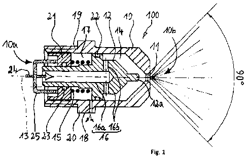
Fig. 1 is an exemplary embodiment of a spray nozzle unit with a closing
means according to the invention in an open position;
Fig. 2 is an exemplary embodiment of the spray nozzle unit with a
closing means according to the invention in a closed position;
Fig. 3 is another exemplary embodiment of a spray nozzle unit with a
closing means according to the invention in a closed position;
Fig. 4 is another exemplary embodiment of the spray nozzle unit with a
closing means according to the invention in an open position;
Fig. 5 is the other exemplary embodiment according to Fig. 3 and Fig. 4
in an exploded view.
PREFERRED EMBODIMENT OF THE INVENTION
Fig. 1 shows an exemplary embodiment of a spray nozzle unit 100 of
the kind that can be used for spraying potentially explosive areas in
underground mining. The spray nozzle unit 100 can be placed in a nozzle
receptacle of a spraying system, which is used in particular to spray a
cutting
head of a selective cut heading machine in underground mining.
The spray nozzle unit 100 exhibits a nozzle body 10 that extends
rotationally symmetrically around a central axis 13. In order to screw in the
nozzle body 10, for example into a nozzle receptacle of a spraying system, the
nozzle body 10 is provided with a threaded section 19. In order to screw the
nozzle body 10 into the nozzle receptacle with a tool, the outside of the
nozzle
body 10 exhibits a wrench geometry 20, for example so as to screw in the
nozzle
body 10 with an open-end wrench, a box wrench, a spanner wrench or the like.
The nozzle body exhibits roughly a cylindrical shape, and extends along the
central axis 13, from a receiving side 10a to a spray side 10b. If the nozzle
body
10 is placed in a nozzle receptacle of a spraying system, a water pressure
prevails on the receiving side 10a, and the water present on the receiving
side
10a can make its way through the nozzle body 10 and be sprayed on the spray
side 10b. To this end, the spray side 10b of the nozzle body 10 exhibits a
nozzle
opening 11, through which the water exits toward the area to be sprayed.
CA 02788428 2012-07-27
Our ref: 1153P001CA01 9
According to the present invention, a closing means 12 is arranged in
the nozzle body 10. The closing means 12 is designed as a clamping piston 12,
and accommodated along the central axis 13 so that it can move back and forth
between a closed position and the depicted open position. The clamping piston
12 is longitudinally guided in the nozzle body 10, and sealed against the
inner
wall of the nozzle body 10 with a sealing element 22. The receiving side 10a
of
the nozzle body 10 exhibits an insert element 21, in which the clamping piston
12 is also guided along the central axis 13 and sealed with another sealing
element 23.
A feed channel 16 exhibiting a first feed channel section 16a and at
least two second feed channel sections 16b extends through the clamping
piston 12. The pressurized water coming from the receiving side 10a is routed
through the feed channel 16a and into the feed port 16. The water supply is
denoted with an arrow 24. The water passes through a filter 25, for example
situated on the rear of the insert element 21 of the nozzle body 10.
The water passes through the first feed channel section 16a and the
second feed channel sections 16b, and enters a pressure chamber 14 inside the
nozzle body 10. The pressure chamber 14 is moveably bordered by the clamping
piston 12. The water pressure present in the pressure chamber 14, for example
at 4 bar, or preferably at 6 bar, moves the clamping piston 12 into the
depicted
open position. At the same time, a locking pin 12a present on the front of the
clamping piston 12 releases the nozzle opening 11.
The movement of the clamping piston 12 toward the depicted open
position takes place against the preloaded force exerted by a spring element
15.
The latter is located on the side of the clamping piston 12 lying opposite the
arrangement of the pressure chamber 14. As a consequence, the spring element
15 preloads the clamping piston 12 in the closing direction, in which the
locking
pin 12a extends through the nozzle opening 11. This prevents contaminants
from being able to get into the nozzle opening 11 in the resting state. For
example, the spring element 15 is designed as a helical compression spring,
and
is clamped between the insert element 21 and a collar of the clamping piston
12. As long as water supply 24 is ongoing, and as long as the pressure chamber
CA 02788428 2012-07-27
Our ref: 1153P001CA01 10
14 is thus pressurized, the clamping piston 12 remains in the depicted open
position, and the water can exit the nozzle opening 12 as illustrated.
The pressure chamber 14 empties like a funnel into the nozzle opening
11 when the clamping piston 12 is in the open position, wherein the surfaces
bordering the pressure chamber 14 exhibit a helical structure, which causes
the
water to exit the nozzle opening 11 with an angular momentum. This yields a
large spraying angle, for example a spraying angle of 90 . Since the pressure
chamber 14 extends rotationally symmetrically around the clamping piston 12
and the locking pin 12a, the twisting effect of the water exiting the nozzle
opening 11 is further intensified. In the position shown behind the nozzle
opening 11, the locking pin 12a can preferably be arranged inside the nozzle
body 10 with the clamping piston 12 in the open position. In particular, it is
possible to geometrically design the clamping piston 12 with the locking pin
12a
and nozzle body 10 with the nozzle opening 11 in such a way as to have a small
distance between the locking pin 12a and nozzle opening 11, so as to elevate
the twisting effect of the exiting water. In particular, the water can as a
result
exit the nozzle opening 11 in a hollow jet, e.g., to achieve a k-value for the
nozzle unit 100 of 1.2 (fluid pressure 6 bar, nozzle opening diameter 3 mm),
for
example.
A low-pressure chamber 17 is formed in the nozzle body 10 on the side
of the clamping piston 12 facing away from the pressure chamber 14. A vent
port 18 fluidically connects the low-pressure chamber 17 with the outside of
the
nozzle body 10. If the clamping piston 12 moves between the closed position
and open position, the volume of the low-pressure chamber 17 changes, and
the vent port 18 allows it to breathe. According to the depiction, the spring
element 15 is arranged inside the low-pressure chamber 17.
Fig. 2 presents another view of the exemplary embodiment of the
spray nozzle unit 100 according to Fig. 1. According to the depiction, the
clamping piston 12 is situated in the closed position. In this arrangement,
the
locking pin 12a extends through the nozzle opening 11. The clamping piston 12
assumes the shown position inside the nozzle body 10 if no water is supplied
via
the receiving side 10a of the spray nozzle unit 100. Arranging the clamping
piston 12a in the closed position diminishes the volume of the pressure
CA 02788428 2012-07-27
Our ref: 1153P001CA01 11
chamber 14, and raises the volume out of the low-pressure chamber 17. As a
consequence, compensating air streams through the vent port 18 into the low-
pressure chamber 17. Also discernible is a geometric configuration of the
clamping piston 12 allowing the rear clamping piston section 12 to be guided
in
the insert element 21. The sealing element 23 also ensures that the low-
pressure chamber 17 is sealed against water pressure on the receiving side 10a
of the spray nozzle unit 100. If the receiving side 10a is again pressurized,
the
water in turn passes through the supply channel 16 and into the pressure
chamber 14, and the clamping piston 12 is moved to the open position against
the force exerted by the spring element 15.
Another exemplary embodiment is depicted on Fig. 3, 4 and 5. The
same reference numbers here denote the same parts as in the first exemplary
embodiment. The difference relative to the initially described spray nozzle
unit
is that the nozzle body 10 here consists of a nozzle connecting part 10c and a
main nozzle part 10d. The latter are joined together by a bore ring (spring
ring)
26. The nozzle opening 11 through which the clamping piston 12 extends is
formed in the main nozzle part 10d. The latter also passes through a helical
body 27, which comprises the closing means 12, and exhibits a circumferential
groove 29 on its conical sealing surface 28 for accommodating the nozzle seal
(0-ring) 30. The clamping piston 12 is arranged on a nozzle piston 31, which
exhibits a guide section 34 whose exterior exhibits a circumferential groove
35
for accommodating the piston seal (0-ring) 36. The guide section 34 is made to
abut the nozzle connecting part 10c via the compression spring 15. The locking
pin 31c is situated on the guide section 34 as the closing means via a
retaining
bolt 31b. After screwed in, the nozzle connecting part 10c is sealed against
the
main nozzle part 10d by the additional piston ring (0-ring) 36. The relief
hole is
no longer required in this embodiment. The clearances between the individual
bodies allow air to escape into the intermediate chamber 37. After
installation,
the nozzle body 10 can no longer be opened, at least not non-destructively.
Dividing the nozzle body 10 into the nozzle connecting part 10c and main
nozzle
part 10d provides a range of various possible connections to choose from
without having to alter the nozzle components. The exemplary embodiment
selected presents a screwed connection of the nozzle connecting part 10c and
CA 02788428 2012-07-27
Our ref: 1153P001CAO1 12
main nozzle part 10d. Any type of threads can here be used. The division into
two parts also makes it possible to turn or tighten the main nozzle part 10d
independently of the nozzle connecting part 10c. This configuration is
especially
important when the nozzle has to be hooked up to piping or silo walls, and
must
remain outwardly tightly sealed (e.g., due to the risk of explosion). In prior
art, a
screw joint had to be incorporated between the nozzle and piping, so that both
ends could be screwed together tightly.
The insert part of the nozzle body 10 is protected against
contaminants in area 10a by a sieve 38. The sieve 38 is fixed in place by a
bore
ring 39, so that too strong a flow cannot tear it away.
The closing means 12 exhibits a helical body 27, the cross section of
which is shown in detail A. Changing the channels 40 in the helical body 27,
e.g.,
the number, position relative to center of gravity, depth and width, makes it
possible to achieve variations in terms of the droplet size, spray angle (jet
cone)
and flow rate (K value variations), without having to change the other
components in any way.
As already described above, the closing means 12 is provided with a
nozzle seal (0-ring) 30 in this embodiment. Given a drop in pressure when the
water supply is stopped, this 0-ring makes it possible to keep the nozzle body
10 sealed to the outside, i.e., the extinguishing water only reaches as far as
the
nozzle outlet opening 11 closed by the clamping piston, and the nozzle line
(not
shown) also remains filled with water. This characteristic is very important
in
extinguishing systems, where very rapid opening times are crucial. Because the
extinguisher supply lines are always filled with water, virtually no delay is
to be
expected in triggering the extinguishing system. Introducing the seal 30 in a
circumferential groove 29 in the conical sealing surface 28 produces no
additional delays in opening the nozzle, since there is no vertical travel.
It is very especially advantageous that the nozzle body 10 be held
tightly even to the outside by the locking piece 27 or pressure hull 27 while
interacting with the seal 30 designed as an 0-ring and exposed to the
resilient
force F exerted by the compression spring 15. The resilient force F of the
compression spring 15 acting on the nozzle piston 31 presses the seal 30 of
the
helical body 27 against the interior wall of the main nozzle part 10d, thereby
CA 02788428 2012-07-27
Our ref: 1153P001CA01 13
preserving the seal. Selecting various spring configurations or various spring
rates also makes it possible to determine the residual pressure in the
extinguisher water supply line and change it as desired.
The invention is not limited in its configuration to the preferred
exemplary embodiments indicated above.
Rather, a number of variants are conceivable, which make use of the
described solution even given embodiments that are different. All features
and/or advantages arising from the claims, specification or drawings,
including
structural details, spatial arrangements and procedural steps, can be
essential
to the invention both taken separately and in the most varied of combinations.
CA 02788428 2012-07-27
Our ref: 1153P001CA01 14
REFERENCE LIST
100 Spray nozzle unit
Nozzle body
5 10a Area/receiving side
10b Spray side
10c Nozzle connecting part
10d Main nozzle part
11 Nozzle opening
10 12 Closing means, clamping piston
12a Locking pin
12b Head section
13 Central axis
14 Pressure chamber
15 Spring element
16 Feed channel
16a First feed channel section
16b Second feed channel section
17 Low-pressure chamber
18 Vent port
19 Threaded section
20 Wrench geometry
21 Insert element
22 Sealing element
23 Sealing element
24 Water supply
25 Filter
26 Bore ring (spring ring)
27 Helical body
28 Sealing surface
29 Circumferential groove
30 Nozzle seal (0-ring)
31 Nozzle piston
CA 02788428 2012-07-27
Our ref: 1153P001CA01 15
34 Guide section
35 Circumferential groove
36 Piston seal (0-ring)
37 Intermediate chamber
38 Sieve
39 Bore ring
40 Channels
F Spring force